
When sub-pixel vision accuracy stops matching shop results
Publication Date
author
When machine vision sub-pixel recognition accuracy looks flawless in lab reports yet fails to match real shop-floor results, quality and safety teams face more than a calibration issue—they face production risk. This article examines why optical precision degrades under vibration, lighting shifts, lens tolerances, and integration errors, helping decision-makers separate marketing claims from verifiable engineering performance.
What does machine vision sub-pixel recognition accuracy actually mean in production terms?
In vendor brochures, machine vision sub-pixel recognition accuracy often sounds like a simple promise: detect edges, centers, gaps, or alignment points more precisely than one pixel. In practice, that statement only becomes meaningful when tied to a real measurement chain. A pixel is not a fixed physical unit until camera resolution, field of view, lens distortion, working distance, lighting geometry, mounting stiffness, and algorithm design are all defined together.
For quality control personnel, the key question is not whether a vision system can compute a sub-pixel value in software. Almost every modern vision platform can. The real question is whether that value remains stable, traceable, and repeatable under the exact thermal, mechanical, and illumination conditions of the shop. Safety managers should care for the same reason: when a vision-guided system drifts silently, false acceptances, false rejects, and unsafe machine actions can all follow.
A system may claim 0.1-pixel or even 0.01-pixel interpolation capability, but interpolation is not identical to real-world metrology accuracy. If one pixel corresponds to 40 microns on the target, then a mathematically derived 0.1-pixel estimate suggests 4 microns. Yet if vibration, focus instability, lens aberration, or part presentation causes edge spread to vary by 12 microns, the numerical result may look precise while the physical answer is wrong. That is why machine vision sub-pixel recognition accuracy should always be discussed alongside repeatability, bias error, uncertainty budget, and environmental sensitivity.
Why do lab results for machine vision sub-pixel recognition accuracy fail on the shop floor?
The gap usually comes from controlled testing versus operational reality. In a lab, integrators often use rigid fixtures, ideal target patterns, fixed temperatures, clean optics, short duty cycles, and stable coaxial or diffused lighting. On a production line, the same system faces machine vibration, airborne contamination, variable reflectivity, slight fixture wear, cable strain, and process drift. Those factors do not merely add noise; they can reshape the image features that the sub-pixel algorithm is trying to estimate.
One common problem is motion-induced blur. Even small blur widens edge transitions, making gradient-based localization less reliable. Another is lighting change. A polished metal part under a slightly shifted angle can create highlights that move independently of the true edge. Lens tolerances matter too. A lens that performs well in the center may show distortion or reduced contrast near the corners, especially if the application uses a wide field of view to cover multiple features at once.
Integration errors are just as important as optics. Exposure timing may not be synchronized with part arrival. Focus may be set at installation but never locked against thermal expansion. Calibration may be performed on a flat artifact while production parts sit at slightly different heights, introducing perspective and magnification error. These issues explain why machine vision sub-pixel recognition accuracy that seems exceptional during acceptance testing may deteriorate once throughput, maintenance cycles, and operator variability enter the picture.
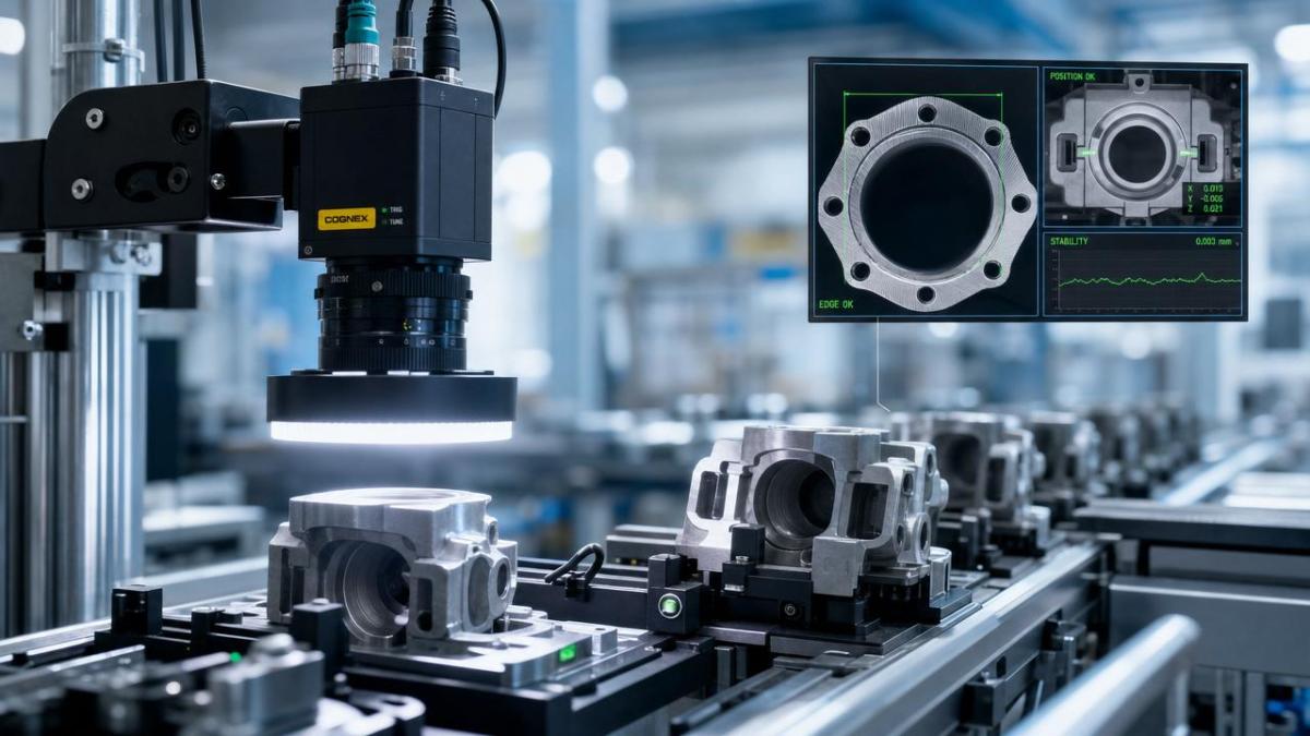
Which shop-floor factors most often degrade machine vision sub-pixel recognition accuracy?
Quality and safety teams usually see the same pattern: the algorithm gets blamed first, while the root cause lies in the physical system. The following comparison helps identify where machine vision sub-pixel recognition accuracy is most vulnerable.
Among these factors, lighting and mechanics usually create the largest hidden errors. A robust camera paired with an unstable mount is still an unstable system. Likewise, excellent software cannot restore information that poor contrast or blur has already destroyed. For this reason, machine vision sub-pixel recognition accuracy should be treated as a system property, not a camera specification.
How should quality control teams verify whether a supplier’s claim is credible?
Start by asking for the test method, not just the headline number. A credible supplier should define the target type, material finish, field of view, pixel size on object, lens model, aperture, lighting arrangement, exposure time, motion condition, ambient temperature range, calibration method, and sample size. Without those details, machine vision sub-pixel recognition accuracy is only a marketing phrase.
Second, request both repeatability and absolute error data. Repeatability shows how tightly the system clusters repeated measurements under the same condition. Absolute error shows how close the result is to the reference value. A system can be repeatable but wrong if calibration is biased. This distinction matters when the application involves safety clearances, adhesive bead width, component seating, drill position, weld path alignment, or dimensional release decisions.
Third, ask for testing under disturbance. If the line will operate near motors, conveyors, or presses, the validation should include mechanical vibration and variable cycle timing. If glossy parts are involved, ask for tests across realistic reflectivity ranges. If production spans multiple shifts, require data over time rather than a single short demonstration. The strongest sign of engineering maturity is not a perfect number under ideal conditions; it is transparent degradation data under non-ideal conditions.
Finally, compare the vision result against an independent measurement reference such as a calibrated stage, CMM, gauge blocks, or a certified artifact. For quality managers, this creates traceability. For safety managers, it creates defensible evidence that the automated decision logic is operating within defined limits.
What are the most common misconceptions about machine vision sub-pixel recognition accuracy?
The first misconception is that more megapixels automatically mean better measurement. Higher resolution helps only if optics, lighting, and mechanical stability preserve usable detail. A noisy, blurred 20 MP image can be less reliable than a clean 5 MP image with proper magnification and illumination.
The second misconception is that sub-pixel output guarantees micron-level truth. It does not. The algorithm can interpolate feature position between pixels, but interpolation depends on image quality and model assumptions. Once the edge profile changes, the estimated point can shift even if the part does not.
The third misconception is that one benchmark applies everywhere. Machine vision sub-pixel recognition accuracy on printed fiducials, matte components, solder pads, machined bores, and reflective stamped metal cannot be assumed equivalent. Surface texture, part geometry, and process variation change the signal available to the camera.
The fourth misconception is that algorithm upgrades alone solve drift. In many cases, the better investment is optical redesign: telecentric lenses, improved shielding, strobed lighting, shorter exposure, rigid brackets, or improved fixturing. Software should refine a stable image formation process, not compensate for fundamentally weak imaging conditions.
When does poor machine vision sub-pixel recognition accuracy become a quality or safety risk?
The risk becomes serious when the measurement directly affects pass/fail decisions, robotic motion, or process interlocks. In dimensional inspection, unstable localization can pass out-of-tolerance features or reject conforming parts, increasing scrap and rework. In assembly verification, it can misjudge connector seating, seal placement, or pin alignment. In robotic guidance, positional drift can drive mispicks, tool collisions, or unsafe approach paths.
Safety managers should pay particular attention when vision data influences guarding logic, zone monitoring, autonomous handling, or high-speed machine correction. If the machine trusts a location estimate that has silently degraded, the result may not be a minor quality defect but a hazardous motion event. That is why machine vision sub-pixel recognition accuracy should be linked to risk classification, alarm thresholds, validation intervals, and fallback operating modes.
A useful rule is this: the tighter the process window, the more dangerous unverified precision becomes. If the allowed positional tolerance is only slightly larger than the combined imaging uncertainty, then small environmental changes can push the system past its safe operating boundary without obvious warning. Engineering teams should therefore define not just target performance, but also minimum acceptable performance and automatic response when the system falls below it.
How can teams improve machine vision sub-pixel recognition accuracy before investing in a full replacement?
In many cases, meaningful gains come from disciplined troubleshooting rather than a new camera purchase. Begin with image formation. Improve contrast at the feature of interest using controlled strobed light, better incidence angle, polarization, or backlighting where suitable. Then reduce motion blur through shorter exposure and brighter synchronized illumination. Next, review the lens choice: if dimensional consistency across depth is critical, telecentric optics may outperform standard lenses despite higher cost.
Mechanical control is equally important. Verify bracket rigidity, cable strain relief, thermal isolation, and fixture repeatability. If the part shifts by more than the sub-pixel algorithm can tolerate, no amount of software tuning will restore dependable metrology. Revisit calibration strategy too. Multi-point verification using certified artifacts can reveal spatial bias that a single-point check misses.
From a process perspective, link the vision system to SPC and maintenance records. A slow drift in measured edge location may correlate with lamp aging, tool wear, contamination, or bearing degradation elsewhere in the line. That connection turns machine vision sub-pixel recognition accuracy from a narrow inspection topic into a broader production health indicator, which is especially valuable in data-driven manufacturing environments.
What should you ask before approving a system, pilot, or supplier comparison?
Before moving forward, quality and safety teams should align on a short list of practical questions. What physical tolerance must the system protect? What is the real pixel-to-micron scale at production working distance? How much vibration, temperature change, and reflectivity variation will exist in service? What reference method will validate machine vision sub-pixel recognition accuracy after installation? How often will recalibration occur, and who owns that task? What alarm or fallback action triggers if confidence, contrast, or repeatability degrades?
These questions help separate showroom performance from manufacturing performance. They also reflect the TSV principle that parameters matter only when tied to operating context, traceable benchmarks, and decision consequence. If you need to confirm a specific solution, parameter set, deployment timeline, quotation basis, or supplier capability, start the discussion with the test conditions, uncertainty limits, maintenance plan, and independent validation method—not with the marketing headline alone.
Search News
Hot Articles
- Carbon Fiber StructuresHow to Specify Aerospace Carbon Fiber Assemblies for Lightweight, Load-Bearing PartsJul 11, 2026
- Machine VisionXiaomi, Alibaba DAMO Academy Drive Open-Source Robotics Model Ecosystem, Lowering Algorithm Development Barriers for Overseas SMEs Adopting Chinese Robotics SolutionsMar 30, 2026
- Cobots & ArmsShanxi 'AI+' Conference Showcases Embodied Intelligence with Multinational Buyer Engagement: Key Industry ImplicationsMar 30, 2026
Popular Tags
Recommended News
 Jul 11, 2026How to Specify Aerospace Carbon Fiber Assemblies for Lightweight, Load-Bearing PartsAerospace carbon fiber assemblies: learn how to specify laminate design, load data, joining methods, and inspection controls for lighter, reliable load-bearing aerospace parts.Elena Rostova (UAV Systems Researcher)
 Mar 30, 2026Xiaomi, Alibaba DAMO Academy Drive Open-Source Robotics Model Ecosystem, Lowering Algorithm Development Barriers for Overseas SMEs Adopting Chinese Robotics SolutionsXiaomi & Alibaba DAMO Academy's open-source robotics models lower algorithm barriers for global SMEs. Boost efficiency in manufacturing, logistics & smart retail with ROS 2 compatible solutions.TSV Data Lab
 Mar 30, 2026Shanxi 'AI+' Conference Showcases Embodied Intelligence with Multinational Buyer Engagement: Key Industry ImplicationsShanxi 'AI+' Conference highlights embodied intelligence with Tesla, Ubtech & Jiantao showcasing multimodal robotics. 40+ global buyers validated tech on-site, creating new B2B channels for industrial automation & AI solutions.Chen Wei (Automation Lead Engineer)
 Mar 30, 2026Zhongguancun Unveils 6G Integrated Sensing-Computing-Intelligence Platform to Empower Embodied Robots for Global Industrial ApplicationsZhongguancun's new 6G platform revolutionizes industrial robotics with <10ms latency, empowering global automotive, logistics & port automation. Discover how this tech boosts China's smart manufacturing exports.TSV Data Lab
 Mar 30, 2026Mech-Mind Tianjin Embodied Intelligence R&D and Production Base Goes Live, Cutting Delivery Time by 20%–30% for Global Customized AMR+Vision SolutionsMech-Mind's Tianjin AMR+Vision production base cuts delivery time by 20%-30% for欧美 & Latin American markets. Discover how this PLd-certified facility accelerates customized robotics solutions for smart manufacturing and logistics.Chen Wei (Automation Lead Engineer)
 Mar 30, 2026Boao Forum Reveals 'Co-evolution of Big and Small Brains' Trend in Humanoid Robots, China's Embodied Intelligence Accelerates Adaptation to Overseas Manufacturing Service ScenariosDiscover how China's humanoid robots, featuring 'Co-evolution of Big and Small Brains,' are revolutionizing global manufacturing. Learn about Embodied Tian Gong 3.0's ISO compliance and overseas deployment at Boao Forum 2026.Chen Wei (Automation Lead Engineer)
 Mar 30, 2026China Railway Industrial Secures Patent for Embodied Robotics in Material Handling, Boosting High-Precision Delivery Capabilities for Overseas Infrastructure and Manufacturing ProjectsChina Railway Industrial's new patent for embodied robotics in material handling boosts high-precision delivery for global infrastructure & manufacturing. Discover how this innovation enhances logistics accuracy in automotive, rail transit & EPC projects.Chen Wei (Automation Lead Engineer)
 Sep 28, 2026Spindle Runout Measurement in Germany: DIN Standards, Methods, and Acceptance LimitsSpindle runout measurement Germany: explore DIN standards, proven methods, acceptance limits, and audit-ready practices for reliable machining quality.Dr. Marcus Vance
 Sep 27, 2026How to Select Wall-Mount Edge Devices for Space-Constrained Factory NetworksWall mount edge devices for space-constrained factories: evaluate workload, thermal design, power resilience, cable access, and network reliability for smarter deployments.TSV Data Lab
 Sep 26, 2026Machining Tolerance Analysis: How to Set Limits That Meet Function and Cost TargetsMachining tolerance analysis: learn how to set functional limits, control tolerance stacks, reduce inspection risk, and balance precision with production cost.Dr. Marcus Vance
 Sep 25, 2026How to Evaluate an Industrial Infrastructure Data Platform for Multi-Site OperationsIndustrial infrastructure data platform evaluation guide for multi-site operations: compare data quality, edge resilience, interoperability, governance, and scalable proof-of-value criteria.Victor Lin (Chief Software Architect)
 Sep 24, 2026How to Select Machine Vision Optics for Accurate Inspection at Different Working DistancesMachine vision optics selection guide for accurate inspection at every working distance. Compare FOV, pixel scale, DOF, distortion, lighting, and telecentric options.TSV Data Lab
 Sep 23, 2026How to Evaluate a Machine Vision System Integrator for High-Speed Inspection LinesChoose a machine vision system integrator with proven expertise in high-speed inspection, reliable reject timing, robust optics, and measurable acceptance criteria.TSV Data Lab
 Sep 28, 2026When is a SCADA API the right choice for connecting plant systems?SCADA API guide: learn when governed plant data integration improves traceability, security, and scalability—without compromising real-time control.Victor Lin (Chief Software Architect)
 Sep 27, 2026How SCADA data integration improves traceability across production linesSCADA data integration connects production-line data to improve traceability, accelerate quality investigations, and strengthen safety decisions.Victor Lin (Chief Software Architect)
 Sep 26, 2026What to define before starting SCADA integration planningSCADA integration planning starts with clear scope, control boundaries, data models, cybersecurity, and testing. Discover the definitions that reduce risk and costly rework.Victor Lin (Chief Software Architect)
 Sep 25, 2026How a smart factory with Industrial IoT reduces production blind spotsDiscover how a smart factory with Industrial IoT turns real-time machine, quality, and workflow data into actionable insights that reduce production blind spots and delivery risks.Victor Lin (Chief Software Architect)
 Sep 24, 2026When does Industrial IoT make smart manufacturing easier to scale?Smart manufacturing Industrial IoT scales when trusted data, interoperable systems, and secure workflows turn connected assets into measurable gains.TSV Data Lab
 Sep 23, 2026What drives ultra-precision machining cost at 1-micron tolerance?Ultra precision machining cost per part at 1 micron tolerance depends on process, material, metrology, and yield. Learn how to compare quotes confidently.Dr. Marcus Vance
 Sep 22, 2026Drone Engine-T550CC Applications: Build the UAV Power System Around the MissionAn application guide for Drone Engine-T550CC integration, covering payload planning, airframe matching, cooling, fuel, vibration, test procedures, documentation, and service preparation.Elena Rostova (UAV Systems Researcher)
 Sep 22, 2026How to Evaluate Industrial Edge Computing Vendors for Factory DeploymentIndustrial edge computing vendor evaluation guide for factories: compare latency, protocol fit, reliability, security, and lifecycle support before deployment.TSV Data Lab
 Sep 21, 2026Drone Payload Integration: Matching Power, Data, and Center of Gravity for Reliable FlightsDrone payload integration made practical: balance power, data, center of gravity, and endurance to build safer, more reliable mission-ready flights.Elena Rostova (UAV Systems Researcher)
 Sep 20, 2026Autonomous Navigation Pricing: Cost Drivers and Budget Benchmarks for AMR ProjectsAutonomous navigation price explained: compare AMR cost drivers, software, sensors, integration, safety, and lifecycle budgets to build a scalable project plan.Chen Wei (Automation Lead Engineer)
 Sep 19, 2026How to Scope Automation Integration Services for Multi-System Factory ProjectsAutomation integration services: learn how to scope multi-system factory projects with clear workflows, interface contracts, safety boundaries, and acceptance criteria.Victor Lin (Chief Software Architect)























