
Machine vision sub-pixel recognition accuracy in real factory light
Publication Date
author
In real factory environments, machine vision sub-pixel recognition accuracy is not determined by ideal laboratory illumination. It is determined by glare from metal parts, vibration from nearby equipment, dust on optics, unstable contrast, and small process variations that accumulate over time. For quality control teams and safety managers, the practical question is simple: can a vision system still measure, detect, and trigger decisions reliably when the line is running under real production conditions? The short answer is that sub-pixel performance is achievable, but only when optics, lighting, mechanics, calibration, and inspection logic are engineered as a complete system rather than purchased as isolated components.
When users search for machine vision sub-pixel recognition accuracy, they are rarely looking for a textbook definition alone. They want to know what level of accuracy is realistic on an operating line, what factors reduce that accuracy, how to verify claims from suppliers, and how to avoid false rejects or missed defects. In other words, they are searching for a decision framework. They need to distinguish between nominal resolution on a datasheet and effective accuracy in production.
For quality control personnel, the main concern is measurement trustworthiness: whether the system can hold tolerances, detect edge positions, identify scratches, gaps, hole centers, labels, or assembly errors without creating unstable inspection results. For safety managers, the concern expands to operational risk: whether bad reads, lighting drift, or dirty optics can lead to unsafe pass decisions, failed interlocks, or inconsistent line behavior. Both groups care less about marketing phrases and more about repeatability, drift resistance, maintenance burden, and proof under their actual lighting conditions.
What sub-pixel recognition accuracy really means on a factory line
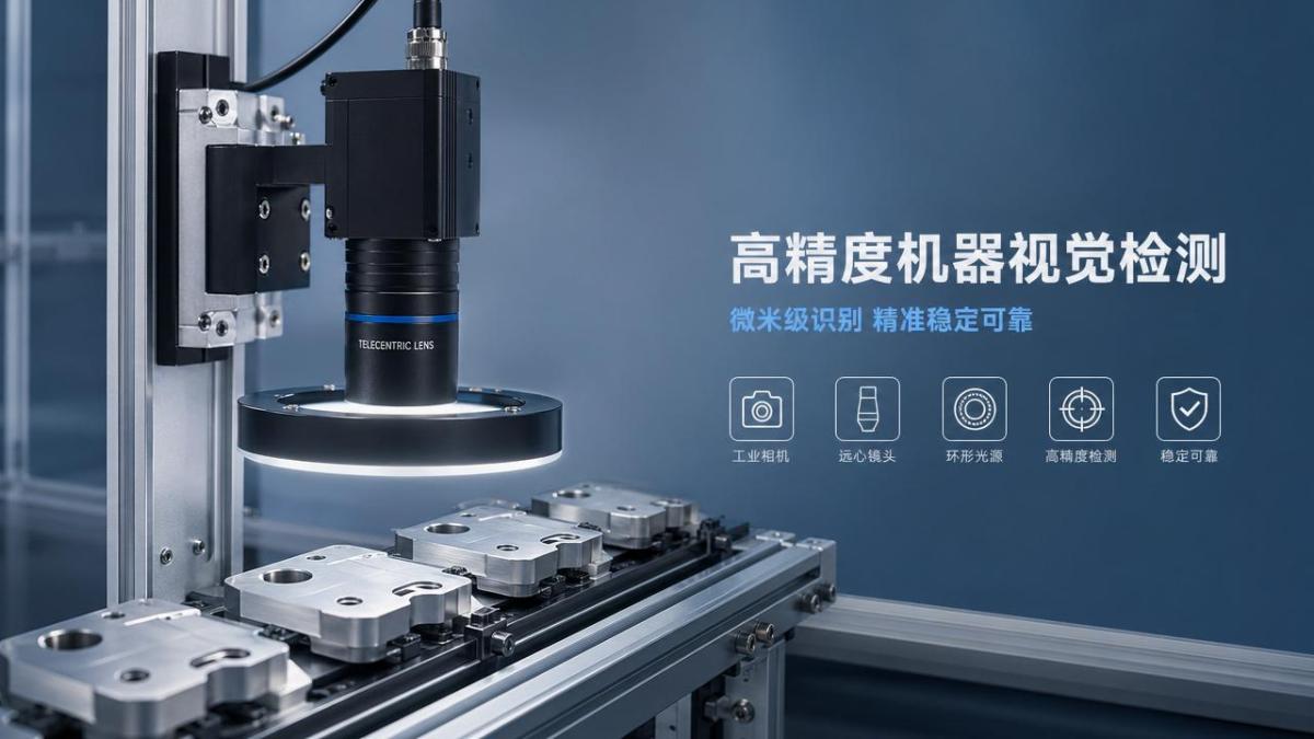
Sub-pixel recognition accuracy means that the vision algorithm estimates a feature location more precisely than one full sensor pixel. This does not violate physics. A camera still captures information at pixel intervals, but grayscale transitions across adjacent pixels allow software to estimate an edge, corner, or center with finer precision. In practice, this is how systems can measure dimensions or positions smaller than the pixel size projected onto the object.
However, this capability is often misunderstood. Sub-pixel estimation is not the same as guaranteed system accuracy. A vendor may demonstrate edge fitting to 0.1 pixel in a stable demo, but your real line may still deliver poor measurement stability if the part vibrates, if lighting changes during a shift, or if reflective surfaces saturate the image. The practical metric is not how well the algorithm performs in isolation, but how well the entire inspection cell maintains repeatability and bias control under production stress.
A useful way to think about it is this: pixel resolution defines the basic information available, sub-pixel processing refines estimation from that information, and real-world industrial accuracy depends on whether the image information remains stable enough for that estimation to remain valid. Once lighting, optics, and mechanics become unstable, sub-pixel mathematics cannot rescue a weak image.
Why lab accuracy often collapses in real factory light
The largest source of performance loss is lighting inconsistency. In a factory, ambient light changes by hour, by season, and sometimes by machine state. Overhead LEDs may flicker relative to camera exposure. Polished metal can produce directional glare. Dark parts may absorb light differently after surface treatment changes. Dust on covers and lenses reduces contrast gradually, which can go unnoticed until false rejects increase. These changes affect edge sharpness and grayscale distribution, both of which directly influence sub-pixel calculations.
Vibration is another major factor. Even very small motion during exposure can blur boundaries enough to shift edge location estimates. On high-speed conveyors or stamping lines, this matters more than many teams expect. If the system exposure time, strobe timing, and mechanical isolation are not well matched, the image may look acceptable to the human eye while still being too unstable for consistent sub-pixel measurement.
Lens quality and setup also matter. Distortion, poor focus across the field, thermal drift, and insufficient depth of field create local differences in magnification and edge clarity. A system may measure accurately in the image center but degrade toward the corners. This is especially important when one camera covers a large field of view and multiple critical features are measured in different locations.
Finally, process variation in the part itself can distort the expected image. Oil film, burrs, rough edges, warped material, and incomplete seating in the fixture can change the geometry or appearance of the target. In those cases, the algorithm may not be wrong; the image no longer corresponds to the inspection model the software assumes.
What quality control and safety managers should verify before trusting a supplier claim
The most important question is not “What sub-pixel accuracy does your camera support?” but “Under what conditions was this accuracy demonstrated?” Ask suppliers to specify the lens, working distance, lighting geometry, exposure time, object material, speed, fixture method, temperature range, and the statistical basis for the result. A result quoted without conditions has little value.
Request both repeatability and total system accuracy data. Repeatability shows how tightly the system clusters repeated measurements of the same feature. Total system accuracy compares the measured result to a traceable reference. Many systems can appear stable while carrying a systematic offset caused by calibration, distortion, or setup geometry. For quality decisions, both metrics matter.
It is also wise to request performance under controlled disturbance. For example, how much does the measured result shift if brightness changes by ten percent, if the part rotates slightly, if dust accumulates on the protective window, or if the camera temperature rises during continuous operation? These tests reveal whether the machine vision sub-pixel recognition accuracy is robust or merely fragile and optimized for a demo condition.
For safety-related inspection points, ask how the system handles uncertainty. If the image quality drops below threshold, does the system fail safe, stop the line, flag a manual check, or continue with low confidence? A technically accurate algorithm still creates risk if the surrounding decision logic is poorly designed.
How to evaluate whether sub-pixel accuracy is enough for your inspection task
The answer starts with converting your process tolerance into image-space requirements. If one pixel on the object corresponds to 0.08 mm and your pass-fail threshold is 0.05 mm, the application may still be feasible with strong optics, contrast, and calibration. But if one pixel corresponds to 0.25 mm and you are trying to make a 0.03 mm decision, no amount of software branding will make the system trustworthy. The image sampling itself is too coarse for that task.
A practical rule is to design margin, not just capability. If the inspection threshold sits too close to the system noise floor, false rejects will rise when lighting or part appearance drifts. Good engineering aims for enough image resolution and enough contrast that the measured feature remains stable even when normal process variation appears. That safety margin is especially important in mixed-model production or multi-shift operations.
Teams should also separate detection tasks from metrology tasks. Detecting whether a label exists is very different from measuring a weld bead width or pin offset. Suppliers sometimes present strong performance in one task category and imply it transfers to another. For quality managers, the right question is whether the inspection objective is presence/absence, classification, positional guidance, dimensional measurement, or defect grading. Each places different demands on sub-pixel recognition.
Design factors that most improve real-world machine vision sub-pixel recognition accuracy
Lighting is the first priority. A stable, purpose-built lighting setup usually improves performance more than changing cameras alone. Backlighting can produce strong edge definition for dimensional checks. Diffuse dome or coaxial lighting can control glare on reflective surfaces. Structured low-angle light can reveal scratches or raised defects. The best solution depends on what feature must be measured, not on generic brightness.
Optics are the second priority. Choose a lens with sufficient resolution, low distortion, appropriate focal length, and enough depth of field for the part variation you expect. Telecentric lenses are often worth considering for high-precision gauging because they reduce magnification changes caused by object height variation. They cost more, but they can dramatically improve consistency when the part position is not perfectly fixed.
Mechanical stability follows close behind. The camera mount, fixture, conveyor, and part presentation must all resist motion and variation. If the object tilts or shifts unpredictably, the imaging geometry changes. For critical measurements, mechanical discipline often determines whether a system remains stable over months rather than days.
Calibration and maintenance complete the picture. A traceable calibration process, distortion correction, scheduled cleaning, light output monitoring, and periodic revalidation are essential. Many systems launch well and degrade quietly because no one owns drift detection. In a factory, maintaining machine vision sub-pixel recognition accuracy is a lifecycle task, not a one-time installation event.
Common failure modes behind false rejects and missed defects
False rejects often come from edge instability rather than obvious software failure. A shiny part that catches a different reflection angle can move the detected edge enough to cross the threshold. A dirty protective cover may reduce local contrast and make a burr appear larger or smaller than it really is. A part that seats slightly differently in the fixture may produce a dimensional reading shift that is blamed on software when the root cause is mechanical.
Missed defects can be even more dangerous, especially in safety-relevant products. If the inspection recipe is tuned too aggressively to reduce false rejects, the system may accept borderline defects when lighting weakens or product finish changes. Another issue is over-reliance on average accuracy. A system may perform well for 95 percent of parts while failing on the exact material finish or orientation that matters most. Reviewing only the average hides tail-risk behavior.
For this reason, quality and safety teams should insist on distribution-based validation. Look at worst-case conditions, not just mean values. Examine performance across shifts, operators, lot changes, and cleaning intervals. A system that is excellent at noon in a clean pilot cell may be unreliable at 2 a.m. on the actual line.
A practical validation checklist for factory acceptance
Before approval, test the system with representative parts from normal production, not hand-selected samples. Include acceptable parts near tolerance limits, known defect samples, surface finish variation, and parts from different lots. If possible, test under normal line speed and actual ambient lighting, with surrounding machines operating.
Measure repeatability at fixed intervals over time rather than only in a short burst. This helps reveal thermal drift, lighting changes, and contamination effects. Record image quality metrics such as contrast, saturation, histogram stability, and focus score alongside measurement results. These process indicators often explain performance changes before reject rates spike.
Set clear escalation rules. Define what happens when confidence drops, when calibration checks fail, or when lighting intensity drifts beyond a limit. Build accountability into maintenance schedules and operator instructions. Quality control needs measurement evidence; safety management needs a controlled response when evidence becomes unreliable.
Finally, compare system output against an independent reference method. For dimensional checks, that may be a calibrated gauge, CMM, or high-precision offline station. For defect detection, it may be validated manual inspection supported by a defect library. Without external reference, it is difficult to know whether the system is accurate or simply consistent with itself.
Business value: when better sub-pixel performance actually matters
Investing in stronger machine vision sub-pixel recognition accuracy pays off when inspection decisions directly affect scrap cost, warranty exposure, throughput stability, or safety compliance. If the process defect cost is low and tolerances are wide, basic imaging may be enough. But in precision assembly, electronics, aerospace components, medical devices, or high-speed packaging, unstable visual measurement can become an expensive hidden source of rework and uncertainty.
For quality control teams, the value is fewer false rejects, clearer traceability, and more confidence when tightening process windows. For safety managers, the value is controlled risk: better confidence that defects are not escaping due to lighting drift or image uncertainty. The real return on investment comes not from the phrase “sub-pixel,” but from reduced ambiguity in daily production decisions.
That is why the best purchasing decision is rarely the cheapest camera or the most impressive demo. It is the system architecture that proves stable under real factory light, real contamination, real shift patterns, and real maintenance behavior. In industrial inspection, engineering truth lives in validated conditions, not headline specifications.
Conclusion
Machine vision sub-pixel recognition accuracy is meaningful only when it survives the realities of the factory floor. For quality control and safety managers, the right mindset is to evaluate the full inspection system: lighting, optics, mechanics, calibration, decision logic, and maintenance discipline. Lab-perfect claims are not enough if glare, vibration, dust, and process variation can move the measurement beyond a safe or useful margin.
If you need to judge whether a system is truly fit for production, focus on three questions. Can it maintain repeatability under real operating conditions? Can it prove total accuracy against a trusted reference? And does it respond safely when image quality degrades? When those questions are answered with data rather than marketing language, machine vision sub-pixel recognition accuracy becomes a practical manufacturing asset rather than a theoretical promise.
Search News
Hot Articles
- Carbon Fiber StructuresHow to Specify Aerospace Carbon Fiber Assemblies for Lightweight, Load-Bearing PartsJul 11, 2026
- Machine VisionXiaomi, Alibaba DAMO Academy Drive Open-Source Robotics Model Ecosystem, Lowering Algorithm Development Barriers for Overseas SMEs Adopting Chinese Robotics SolutionsMar 30, 2026
- Cobots & ArmsShanxi 'AI+' Conference Showcases Embodied Intelligence with Multinational Buyer Engagement: Key Industry ImplicationsMar 30, 2026
Popular Tags
Recommended News
 Jul 11, 2026How to Specify Aerospace Carbon Fiber Assemblies for Lightweight, Load-Bearing PartsAerospace carbon fiber assemblies: learn how to specify laminate design, load data, joining methods, and inspection controls for lighter, reliable load-bearing aerospace parts.Elena Rostova (UAV Systems Researcher)
 Mar 30, 2026Xiaomi, Alibaba DAMO Academy Drive Open-Source Robotics Model Ecosystem, Lowering Algorithm Development Barriers for Overseas SMEs Adopting Chinese Robotics SolutionsXiaomi & Alibaba DAMO Academy's open-source robotics models lower algorithm barriers for global SMEs. Boost efficiency in manufacturing, logistics & smart retail with ROS 2 compatible solutions.TSV Data Lab
 Mar 30, 2026Shanxi 'AI+' Conference Showcases Embodied Intelligence with Multinational Buyer Engagement: Key Industry ImplicationsShanxi 'AI+' Conference highlights embodied intelligence with Tesla, Ubtech & Jiantao showcasing multimodal robotics. 40+ global buyers validated tech on-site, creating new B2B channels for industrial automation & AI solutions.Chen Wei (Automation Lead Engineer)
 Mar 30, 2026Zhongguancun Unveils 6G Integrated Sensing-Computing-Intelligence Platform to Empower Embodied Robots for Global Industrial ApplicationsZhongguancun's new 6G platform revolutionizes industrial robotics with <10ms latency, empowering global automotive, logistics & port automation. Discover how this tech boosts China's smart manufacturing exports.TSV Data Lab
 Mar 30, 2026Mech-Mind Tianjin Embodied Intelligence R&D and Production Base Goes Live, Cutting Delivery Time by 20%–30% for Global Customized AMR+Vision SolutionsMech-Mind's Tianjin AMR+Vision production base cuts delivery time by 20%-30% for欧美 & Latin American markets. Discover how this PLd-certified facility accelerates customized robotics solutions for smart manufacturing and logistics.Chen Wei (Automation Lead Engineer)
 Mar 30, 2026Boao Forum Reveals 'Co-evolution of Big and Small Brains' Trend in Humanoid Robots, China's Embodied Intelligence Accelerates Adaptation to Overseas Manufacturing Service ScenariosDiscover how China's humanoid robots, featuring 'Co-evolution of Big and Small Brains,' are revolutionizing global manufacturing. Learn about Embodied Tian Gong 3.0's ISO compliance and overseas deployment at Boao Forum 2026.Chen Wei (Automation Lead Engineer)
 Mar 30, 2026China Railway Industrial Secures Patent for Embodied Robotics in Material Handling, Boosting High-Precision Delivery Capabilities for Overseas Infrastructure and Manufacturing ProjectsChina Railway Industrial's new patent for embodied robotics in material handling boosts high-precision delivery for global infrastructure & manufacturing. Discover how this innovation enhances logistics accuracy in automotive, rail transit & EPC projects.Chen Wei (Automation Lead Engineer)
 Sep 28, 2026Spindle Runout Measurement in Germany: DIN Standards, Methods, and Acceptance LimitsSpindle runout measurement Germany: explore DIN standards, proven methods, acceptance limits, and audit-ready practices for reliable machining quality.Dr. Marcus Vance
 Sep 27, 2026How to Select Wall-Mount Edge Devices for Space-Constrained Factory NetworksWall mount edge devices for space-constrained factories: evaluate workload, thermal design, power resilience, cable access, and network reliability for smarter deployments.TSV Data Lab
 Sep 26, 2026Machining Tolerance Analysis: How to Set Limits That Meet Function and Cost TargetsMachining tolerance analysis: learn how to set functional limits, control tolerance stacks, reduce inspection risk, and balance precision with production cost.Dr. Marcus Vance
 Sep 25, 2026How to Evaluate an Industrial Infrastructure Data Platform for Multi-Site OperationsIndustrial infrastructure data platform evaluation guide for multi-site operations: compare data quality, edge resilience, interoperability, governance, and scalable proof-of-value criteria.Victor Lin (Chief Software Architect)
 Sep 24, 2026How to Select Machine Vision Optics for Accurate Inspection at Different Working DistancesMachine vision optics selection guide for accurate inspection at every working distance. Compare FOV, pixel scale, DOF, distortion, lighting, and telecentric options.TSV Data Lab
 Sep 23, 2026How to Evaluate a Machine Vision System Integrator for High-Speed Inspection LinesChoose a machine vision system integrator with proven expertise in high-speed inspection, reliable reject timing, robust optics, and measurable acceptance criteria.TSV Data Lab
 Sep 28, 2026When is a SCADA API the right choice for connecting plant systems?SCADA API guide: learn when governed plant data integration improves traceability, security, and scalability—without compromising real-time control.Victor Lin (Chief Software Architect)
 Sep 27, 2026How SCADA data integration improves traceability across production linesSCADA data integration connects production-line data to improve traceability, accelerate quality investigations, and strengthen safety decisions.Victor Lin (Chief Software Architect)
 Sep 26, 2026What to define before starting SCADA integration planningSCADA integration planning starts with clear scope, control boundaries, data models, cybersecurity, and testing. Discover the definitions that reduce risk and costly rework.Victor Lin (Chief Software Architect)
 Sep 25, 2026How a smart factory with Industrial IoT reduces production blind spotsDiscover how a smart factory with Industrial IoT turns real-time machine, quality, and workflow data into actionable insights that reduce production blind spots and delivery risks.Victor Lin (Chief Software Architect)
 Sep 24, 2026When does Industrial IoT make smart manufacturing easier to scale?Smart manufacturing Industrial IoT scales when trusted data, interoperable systems, and secure workflows turn connected assets into measurable gains.TSV Data Lab
 Sep 23, 2026What drives ultra-precision machining cost at 1-micron tolerance?Ultra precision machining cost per part at 1 micron tolerance depends on process, material, metrology, and yield. Learn how to compare quotes confidently.Dr. Marcus Vance
 Sep 22, 2026Drone Engine-T550CC Applications: Build the UAV Power System Around the MissionAn application guide for Drone Engine-T550CC integration, covering payload planning, airframe matching, cooling, fuel, vibration, test procedures, documentation, and service preparation.Elena Rostova (UAV Systems Researcher)
 Sep 22, 2026How to Evaluate Industrial Edge Computing Vendors for Factory DeploymentIndustrial edge computing vendor evaluation guide for factories: compare latency, protocol fit, reliability, security, and lifecycle support before deployment.TSV Data Lab
 Sep 21, 2026Drone Payload Integration: Matching Power, Data, and Center of Gravity for Reliable FlightsDrone payload integration made practical: balance power, data, center of gravity, and endurance to build safer, more reliable mission-ready flights.Elena Rostova (UAV Systems Researcher)
 Sep 20, 2026Autonomous Navigation Pricing: Cost Drivers and Budget Benchmarks for AMR ProjectsAutonomous navigation price explained: compare AMR cost drivers, software, sensors, integration, safety, and lifecycle budgets to build a scalable project plan.Chen Wei (Automation Lead Engineer)
 Sep 19, 2026How to Scope Automation Integration Services for Multi-System Factory ProjectsAutomation integration services: learn how to scope multi-system factory projects with clear workflows, interface contracts, safety boundaries, and acceptance criteria.Victor Lin (Chief Software Architect)























