
Machine vision lens specs that change inspection results
Publication Date
author
Small differences in machine vision lens specifications can trigger major shifts in inspection accuracy, false reject rates, and compliance confidence. For quality control and safety managers, understanding how resolution, distortion, focal length, and lighting compatibility affect detection results is essential to reducing risk and improving consistency. This article explains which lens parameters matter most and how they directly influence real-world inspection performance.
When inspection results become unstable, many teams first question the camera, software, or lighting. In practice, the lens is often the hidden variable that changes everything. A machine vision system can use a high-quality sensor and reliable algorithm, yet still miss defects, overcall good parts, or fail audits if the lens is poorly matched to the application.
For quality control and safety managers, the key takeaway is simple: machine vision lens specifications are not minor engineering details. They directly affect measurement repeatability, defect detection sensitivity, edge clarity, field coverage, and the confidence level behind pass/fail decisions. The right lens reduces operational risk. The wrong lens quietly increases scrap, rework, downtime, and compliance exposure.
This article focuses on the machine vision lens specifications that most often change inspection results in real production environments. Rather than listing parameters in isolation, it explains how each one influences inspection performance, where mismatches happen, and how to evaluate lens choices in a way that supports quality and safety targets.
Why lens specifications matter more than many inspection teams expect
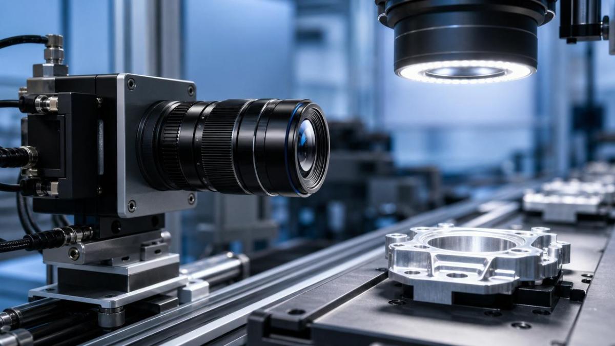
In machine vision, the lens determines how the object is projected onto the image sensor. That projection affects whether the system can separate a scratch from texture, measure a gap correctly, read a laser mark, or detect a damaged edge before the part moves downstream. Even if the software appears advanced, it can only analyze the image quality delivered by the optics.
For inspection managers, this is where hidden costs begin. A lens that is “good enough” on a lab bench may become unstable on the line because of vibration, heat, changing working distance, or reflections from glossy materials. The result is not always a total inspection failure. More often, it is a slower and more expensive decline: rising false rejects, inconsistent thresholds between shifts, repeated re-teaching, and uncertain root-cause analysis.
That is why machine vision lens specifications should be reviewed as risk-control parameters, not just optical features. The most important question is not whether a lens has a certain number in its datasheet. It is whether that specification supports the actual defect size, tolerance band, line speed, object geometry, and environmental conditions of the inspection task.
Resolution and MTF: the specifications that decide whether small defects are truly visible
Resolution is often the first lens parameter buyers compare, but many teams interpret it too simply. A lens may be advertised for a sensor size or megapixel class, yet still fail to preserve enough detail at the area of interest. What matters is not headline megapixels alone, but whether the lens can maintain usable contrast at the spatial frequencies required for your inspection target.
This is where MTF, or modulation transfer function, becomes critical. MTF describes how well a lens transfers contrast from the object to the image at different detail levels. In practical terms, it helps determine whether tiny cracks, faint print defects, edge chips, or subtle contamination remain distinguishable from background noise.
For a quality manager, the real-world implication is straightforward. If the lens cannot support the effective pixel resolution required by the defect size, inspection reliability drops before the algorithm even begins. The software may still produce a pass/fail result, but its confidence is built on a degraded image. That increases the probability of both escapes and false alarms.
A common mistake is to match a high-resolution camera with an underperforming lens. This creates the illusion of a capable system because the sensor count looks strong on paper. But if the lens softens edges or loses contrast near the required feature size, the extra pixels do not translate into better inspection. They simply capture a larger amount of blurred information.
When reviewing machine vision lens specifications, teams should ask three practical questions. First, what is the smallest defect or dimensional deviation that must be detected? Second, how many pixels should represent that feature for reliable classification or measurement? Third, can the lens maintain sufficient sharpness not only in the center, but across the full inspection field?
Distortion: the lens issue that quietly corrupts measurement accuracy
For presence/absence checks, distortion may appear manageable. For dimensional inspection, alignment verification, robotic guidance, or safety-critical positioning, it becomes much more serious. Distortion changes the geometric relationship between the object and the image, which means measured distances can shift depending on where the feature appears in the field of view.
Barrel distortion makes straight lines bow outward. Pincushion distortion bends them inward. Even moderate distortion can create errors in gauging, hole-position verification, label placement, seal inspection, and edge alignment measurements. This is especially problematic when one camera must inspect a large field and decisions depend on tolerance bands that are already tight.
Software calibration can compensate for some distortion, but it should not be treated as a universal fix. Compensation adds complexity, depends on calibration stability, and may not fully recover image fidelity under all conditions. If the inspection system experiences mechanical drift, lens replacement, re-mounting, or temperature-related change, calibration quality can degrade over time.
For safety and compliance applications, lower distortion optics often provide a stronger operational foundation because they reduce dependence on correction layers. This does not mean every system needs ultra-telecentric or premium metrology optics. It means the acceptable distortion level must be tied directly to the measurement error budget and process risk, not chosen for cost alone.
Focal length and field of view: the tradeoff between seeing enough and seeing clearly enough
Focal length defines how much of the scene the lens can capture at a given working distance. In production discussions, this usually becomes a field-of-view conversation: can one camera inspect the entire part, or is a narrower view needed to resolve the required details? The answer shapes both image quality and system economics.
A shorter focal length provides a wider field of view, which can reduce hardware count and simplify installation. But widening the view also spreads available pixels across a larger area. That means fewer pixels per millimeter on the target, which lowers the system’s ability to detect fine features. If the defect criteria are small, a wide field may be operationally convenient but technically insufficient.
A longer focal length increases magnification and can improve defect visibility, yet it also narrows coverage and may require greater working distance or tighter alignment. On crowded lines, especially where guarding, conveyors, and safety enclosures limit placement, the theoretically ideal focal length may be hard to implement.
This is why the correct selection process begins with inspection requirements, not catalog browsing. Quality teams should define the necessary field coverage, minimum detectable feature size, target pixel density, and installation constraints before comparing focal lengths. Otherwise, the lens decision becomes reactive and often leads to a compromise that weakens one critical performance area.
For safety managers, there is another consideration. If a field of view is too tight, relevant context may be excluded, such as adjacent components, edge conditions, or positional cues needed for safe classification. If it is too wide, small anomalies become invisible. Effective lens choice balances context with defect sensitivity.
Aperture, depth of field, and exposure stability: why consistent focus matters for pass/fail confidence
Aperture affects how much light enters the lens, but its inspection impact goes far beyond brightness. It also changes depth of field, which determines how much of the object remains acceptably sharp despite height variation, tilt, or part-position change. In industrial inspection, this is often the difference between stable results and recurring exceptions.
If the aperture is too wide, the image may be bright and fast to expose, but depth of field becomes shallow. Small changes in part height, fixture tolerance, or conveyor vibration can push critical features out of focus. For systems inspecting uneven surfaces, assembled products, or components with multiple height planes, this creates inconsistent detection performance.
If the aperture is too narrow, depth of field improves, but diffraction can reduce sharpness, especially on high-resolution systems. Exposure time may also need to increase if lighting is insufficient, introducing motion blur on fast lines. This is why aperture should never be set independently of line speed, lighting intensity, and resolution requirements.
From a management perspective, focus stability is a quality cost issue. A system that performs well only within a narrow setup window requires more maintenance attention and is more vulnerable to drift. A more robust optical setup may cost more upfront, but it usually reduces false rejects, troubleshooting time, and operator intervention over the life of the line.
Sensor format and lens compatibility: a common source of underperformance
One of the most overlooked machine vision lens specifications is compatibility with sensor size and pixel pitch. A lens designed for a smaller image circle may produce vignetting or reduced clarity at the edges when paired with a larger sensor. Even when the image fills the sensor, optical performance may not be uniform enough to support reliable inspection across the full frame.
Pixel size also matters. Modern sensors with small pixels demand stronger optical performance because they sample finer detail. A lens that worked acceptably with older, larger-pixel cameras may become the limiting factor after a camera upgrade. This often surprises teams that assume replacing the camera alone will improve detection capability.
For procurement and quality leaders, this means specifications must be reviewed as a system, not as separate components. Camera, lens, lighting, working distance, and inspection target must be evaluated together. A mismatch in one area can erase the benefits of investment in another.
Lighting compatibility and spectral response: the difference between a visible defect and an invisible one
Machine vision lenses do not work independently of lighting. Their coatings, transmission efficiency, and spectral behavior influence how the system handles backlight, coaxial illumination, structured light, infrared, or ultraviolet setups. In some inspections, the lens-lighting interaction matters as much as nominal resolution.
For example, reflective surfaces may generate glare that hides scratches or edge defects unless the lens works well with polarized or controlled-angle lighting. Printed codes may appear clear in visible light but become more reliable under near-infrared. Some materials reveal contamination only under specific wavelengths. If the lens is not optimized for that spectral range, inspection contrast may collapse.
This is particularly important in safety-related applications where subtle defects must be detected before failure risk increases. Choosing machine vision lens specifications without considering the lighting method often leads to unstable thresholds and repeated tuning. The system may seem functional during initial setup but perform poorly when material finish, ambient light, or surface condition shifts.
The practical rule is simple: validate lens performance under the exact lighting strategy used in production. Bench tests under general room conditions are not enough. Inspection confidence comes from application-specific contrast, not generic image appearance.
Telecentricity and perspective control: when standard lenses are not enough
Some inspection tasks require more than a conventional lens can provide. When parts vary in height, when measurements must remain stable across small position changes, or when edge accuracy is critical, telecentric lenses can significantly improve consistency. Their main advantage is reducing perspective error and maintaining magnification more consistently within a defined depth range.
This matters in gauging outer diameters, checking fill levels, measuring gaps, or inspecting components where object placement cannot be perfectly controlled. With a standard lens, slight height differences can make parts appear larger or smaller than they really are. A telecentric lens helps reduce that effect.
However, telecentric optics are larger, more expensive, and not necessary for every application. The decision should be based on the cost of measurement uncertainty. If the inspection result feeds compliance documentation, final acceptance, or safety release, the additional optical control may be justified. If the task is only rough presence detection, it may not be.
How quality and safety managers should evaluate lens choices
The best evaluation method is not to ask which lens is “best,” but which lens keeps inspection risk within acceptable limits. That requires a structured review process tied to operational outcomes. Start with the defect classes, tolerance limits, and false reject tolerance of the process. Then define the optical conditions needed to support those requirements.
A practical evaluation framework includes the following questions: What is the smallest critical feature? What repeatability is required? Is the application detection, classification, measurement, or guidance? How much height variation exists? What are the lighting conditions? How fast is the line? How much environmental vibration or temperature change occurs? What is the cost of an escape versus a false reject?
These questions shift the conversation from component selection to risk management. They also help non-optical stakeholders make stronger decisions because the lens is assessed against production impact rather than technical marketing language.
When possible, require sample images from real parts across acceptable and borderline conditions. Review center and edge clarity, contrast stability, and measurement repeatability. If suppliers provide only ideal-case demonstrations, the validation is incomplete. The lens should prove itself under the conditions that actually create uncertainty on the line.
Common purchasing mistakes that lead to poor inspection results
Several recurring mistakes cause machine vision systems to underperform even when budgets are reasonable. The first is choosing by megapixel compatibility alone. The second is ignoring distortion because software can “fix it later.” The third is selecting a wide field of view without recalculating the resulting defect resolution.
Other frequent issues include overlooking depth-of-field limits, assuming all lenses perform similarly within a mount type, and testing optics only on static samples instead of real production motion. Another mistake is treating lighting problems and lens problems as separate when they are often linked.
For managers, the lesson is that lens selection should be part of process validation, not an afterthought during purchasing. Many inspection problems that appear to be software tuning issues are actually rooted in optical mismatch.
Conclusion: better lens decisions produce more trustworthy inspection systems
If inspection results are changing unexpectedly, the lens should be one of the first elements reviewed. Among all machine vision lens specifications, the most consequential are resolution with MTF, distortion, focal length, aperture, sensor compatibility, lighting compatibility, and, when required, telecentricity. These factors determine whether the system sees the right detail in the right way, consistently enough to support confident decisions.
For quality control and safety managers, the business value is clear. Better optical matching reduces false rejects, lowers escape risk, improves audit defensibility, and shortens troubleshooting cycles. It also creates a stronger foundation for process standardization across lines and plants.
The most effective approach is to stop viewing lens specifications as passive datasheet entries. They are active drivers of inspection performance. When evaluated against defect size, tolerance, geometry, lighting, and line conditions, they become powerful tools for improving consistency and reducing risk. In machine vision, better images do not just look better. They lead to better decisions.
Search News
Hot Articles
- Carbon Fiber StructuresHow to Specify Aerospace Carbon Fiber Assemblies for Lightweight, Load-Bearing PartsJul 11, 2026
- Machine VisionXiaomi, Alibaba DAMO Academy Drive Open-Source Robotics Model Ecosystem, Lowering Algorithm Development Barriers for Overseas SMEs Adopting Chinese Robotics SolutionsMar 30, 2026
- Cobots & ArmsShanxi 'AI+' Conference Showcases Embodied Intelligence with Multinational Buyer Engagement: Key Industry ImplicationsMar 30, 2026
Popular Tags
Recommended News
 Jul 11, 2026How to Specify Aerospace Carbon Fiber Assemblies for Lightweight, Load-Bearing PartsAerospace carbon fiber assemblies: learn how to specify laminate design, load data, joining methods, and inspection controls for lighter, reliable load-bearing aerospace parts.Elena Rostova (UAV Systems Researcher)
 Mar 30, 2026Xiaomi, Alibaba DAMO Academy Drive Open-Source Robotics Model Ecosystem, Lowering Algorithm Development Barriers for Overseas SMEs Adopting Chinese Robotics SolutionsXiaomi & Alibaba DAMO Academy's open-source robotics models lower algorithm barriers for global SMEs. Boost efficiency in manufacturing, logistics & smart retail with ROS 2 compatible solutions.TSV Data Lab
 Mar 30, 2026Shanxi 'AI+' Conference Showcases Embodied Intelligence with Multinational Buyer Engagement: Key Industry ImplicationsShanxi 'AI+' Conference highlights embodied intelligence with Tesla, Ubtech & Jiantao showcasing multimodal robotics. 40+ global buyers validated tech on-site, creating new B2B channels for industrial automation & AI solutions.Chen Wei (Automation Lead Engineer)
 Mar 30, 2026Zhongguancun Unveils 6G Integrated Sensing-Computing-Intelligence Platform to Empower Embodied Robots for Global Industrial ApplicationsZhongguancun's new 6G platform revolutionizes industrial robotics with <10ms latency, empowering global automotive, logistics & port automation. Discover how this tech boosts China's smart manufacturing exports.TSV Data Lab
 Mar 30, 2026Mech-Mind Tianjin Embodied Intelligence R&D and Production Base Goes Live, Cutting Delivery Time by 20%–30% for Global Customized AMR+Vision SolutionsMech-Mind's Tianjin AMR+Vision production base cuts delivery time by 20%-30% for欧美 & Latin American markets. Discover how this PLd-certified facility accelerates customized robotics solutions for smart manufacturing and logistics.Chen Wei (Automation Lead Engineer)
 Mar 30, 2026Boao Forum Reveals 'Co-evolution of Big and Small Brains' Trend in Humanoid Robots, China's Embodied Intelligence Accelerates Adaptation to Overseas Manufacturing Service ScenariosDiscover how China's humanoid robots, featuring 'Co-evolution of Big and Small Brains,' are revolutionizing global manufacturing. Learn about Embodied Tian Gong 3.0's ISO compliance and overseas deployment at Boao Forum 2026.Chen Wei (Automation Lead Engineer)
 Mar 30, 2026China Railway Industrial Secures Patent for Embodied Robotics in Material Handling, Boosting High-Precision Delivery Capabilities for Overseas Infrastructure and Manufacturing ProjectsChina Railway Industrial's new patent for embodied robotics in material handling boosts high-precision delivery for global infrastructure & manufacturing. Discover how this innovation enhances logistics accuracy in automotive, rail transit & EPC projects.Chen Wei (Automation Lead Engineer)
 Sep 28, 2026Spindle Runout Measurement in Germany: DIN Standards, Methods, and Acceptance LimitsSpindle runout measurement Germany: explore DIN standards, proven methods, acceptance limits, and audit-ready practices for reliable machining quality.Dr. Marcus Vance
 Sep 27, 2026How to Select Wall-Mount Edge Devices for Space-Constrained Factory NetworksWall mount edge devices for space-constrained factories: evaluate workload, thermal design, power resilience, cable access, and network reliability for smarter deployments.TSV Data Lab
 Sep 26, 2026Machining Tolerance Analysis: How to Set Limits That Meet Function and Cost TargetsMachining tolerance analysis: learn how to set functional limits, control tolerance stacks, reduce inspection risk, and balance precision with production cost.Dr. Marcus Vance
 Sep 25, 2026How to Evaluate an Industrial Infrastructure Data Platform for Multi-Site OperationsIndustrial infrastructure data platform evaluation guide for multi-site operations: compare data quality, edge resilience, interoperability, governance, and scalable proof-of-value criteria.Victor Lin (Chief Software Architect)
 Sep 24, 2026How to Select Machine Vision Optics for Accurate Inspection at Different Working DistancesMachine vision optics selection guide for accurate inspection at every working distance. Compare FOV, pixel scale, DOF, distortion, lighting, and telecentric options.TSV Data Lab
 Sep 23, 2026How to Evaluate a Machine Vision System Integrator for High-Speed Inspection LinesChoose a machine vision system integrator with proven expertise in high-speed inspection, reliable reject timing, robust optics, and measurable acceptance criteria.TSV Data Lab
 Sep 28, 2026When is a SCADA API the right choice for connecting plant systems?SCADA API guide: learn when governed plant data integration improves traceability, security, and scalability—without compromising real-time control.Victor Lin (Chief Software Architect)
 Sep 27, 2026How SCADA data integration improves traceability across production linesSCADA data integration connects production-line data to improve traceability, accelerate quality investigations, and strengthen safety decisions.Victor Lin (Chief Software Architect)
 Sep 26, 2026What to define before starting SCADA integration planningSCADA integration planning starts with clear scope, control boundaries, data models, cybersecurity, and testing. Discover the definitions that reduce risk and costly rework.Victor Lin (Chief Software Architect)
 Sep 25, 2026How a smart factory with Industrial IoT reduces production blind spotsDiscover how a smart factory with Industrial IoT turns real-time machine, quality, and workflow data into actionable insights that reduce production blind spots and delivery risks.Victor Lin (Chief Software Architect)
 Sep 24, 2026When does Industrial IoT make smart manufacturing easier to scale?Smart manufacturing Industrial IoT scales when trusted data, interoperable systems, and secure workflows turn connected assets into measurable gains.TSV Data Lab
 Sep 23, 2026What drives ultra-precision machining cost at 1-micron tolerance?Ultra precision machining cost per part at 1 micron tolerance depends on process, material, metrology, and yield. Learn how to compare quotes confidently.Dr. Marcus Vance
 Sep 22, 2026Drone Engine-T550CC Applications: Build the UAV Power System Around the MissionAn application guide for Drone Engine-T550CC integration, covering payload planning, airframe matching, cooling, fuel, vibration, test procedures, documentation, and service preparation.Elena Rostova (UAV Systems Researcher)
 Sep 22, 2026How to Evaluate Industrial Edge Computing Vendors for Factory DeploymentIndustrial edge computing vendor evaluation guide for factories: compare latency, protocol fit, reliability, security, and lifecycle support before deployment.TSV Data Lab
 Sep 21, 2026Drone Payload Integration: Matching Power, Data, and Center of Gravity for Reliable FlightsDrone payload integration made practical: balance power, data, center of gravity, and endurance to build safer, more reliable mission-ready flights.Elena Rostova (UAV Systems Researcher)
 Sep 20, 2026Autonomous Navigation Pricing: Cost Drivers and Budget Benchmarks for AMR ProjectsAutonomous navigation price explained: compare AMR cost drivers, software, sensors, integration, safety, and lifecycle budgets to build a scalable project plan.Chen Wei (Automation Lead Engineer)
 Sep 19, 2026How to Scope Automation Integration Services for Multi-System Factory ProjectsAutomation integration services: learn how to scope multi-system factory projects with clear workflows, interface contracts, safety boundaries, and acceptance criteria.Victor Lin (Chief Software Architect)























