
Industrial ethernet switch PCBA failures often come from thermal design
Publication Date
author
Many industrial ethernet switch PCBA failures are not caused by components alone, but by overlooked thermal design limits that slowly degrade reliability in the field. For after-sales maintenance teams, understanding how heat buildup affects solder joints, power modules, and signal stability is essential to faster diagnosis, fewer repeat repairs, and more accurate root-cause analysis.
Why do so many industrial ethernet switch PCBA failures trace back to thermal design?
This question matters because field returns often create a false picture. A failed port, unstable uplink, reboot loop, or dead power stage may look like a random component issue, yet the deeper cause is frequently thermal stress accumulated over months or years. In an industrial ethernet switch PCBA, heat is rarely distributed evenly. Hotspots build around switching chips, PHY devices, DC-DC converters, PoE power sections, and surge protection networks. If the thermal path from those parts to copper planes, heat spreaders, enclosure walls, or airflow channels is weak, the board begins aging in ways that are not obvious during short bench tests.
For after-sales maintenance staff, this explains why replacing a burned regulator or reworking a suspicious solder joint may restore operation only temporarily. The replacement part is entering the same thermal environment that caused the first failure. Over time, repeated temperature cycling expands and contracts dissimilar materials on the industrial ethernet switch PCBA. That can weaken BGA connections, dry out electrolytic capacitors, increase MOSFET losses, and shift clock stability. Thermal design, in other words, is not only about peak temperature. It is about long-term reliability under continuous load, cabinet crowding, dust, vibration, and summer ambient extremes.
TSV’s data-driven view is simple: parameters do not lie. If a board operates near the edge of its thermal budget, even compliant components can fail early in real installations. That is why root-cause analysis must move beyond part numbers and include layout density, copper thickness, vent placement, interface materials, and derating assumptions.
What are the most common heat-related symptoms maintenance teams should recognize first?
In the field, thermal failure rarely announces itself as “overheating” on a label. Instead, the industrial ethernet switch PCBA shows indirect symptoms that vary with load and ambient temperature. A unit may pass startup checks in the morning and begin dropping packets by midday. Another may run correctly with one or two ports active but fail when all PoE ports supply cameras or access points. A third may reboot only when installed near drives, power supplies, or other heat sources inside a sealed cabinet.
Typical thermal warning signs include intermittent link loss, rising packet error rates, unexplained broadcast storms caused by unstable switching logic, PoE power negotiation problems, random watchdog resets, distorted console logs, and localized discoloration on the PCB. Maintenance teams should also look for cracked conformal coating near hot devices, capacitor bulging, hardened thermal pads, and signs that enclosure paint has faded close to internal heat sources. These clues often indicate that the industrial ethernet switch PCBA has been operating above its intended thermal comfort zone rather than suffering a one-time electrical accident.
A practical mistake is to test a returned board only at room temperature and low traffic. That can hide the real problem. Heat-related failures often appear only after soak time, full port loading, PoE draw, or elevated cabinet temperature. Recreating those conditions is critical if the goal is to prevent repeat service calls.
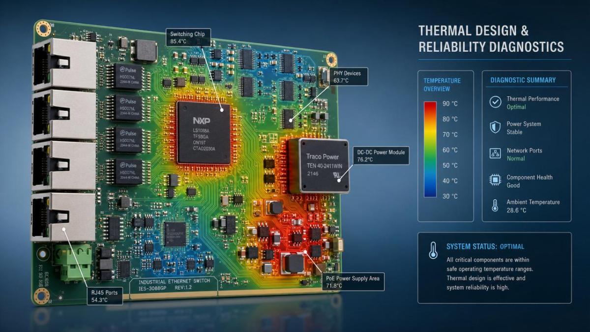
Which areas on an industrial ethernet switch PCBA are usually the hottest and most failure-prone?
Not all hot parts are equally dangerous. The maintenance priority should focus on areas where temperature and functional criticality overlap. The first zone is the power conversion section. DC input protection, rectification, PoE controllers, transformers, switching MOSFETs, and output inductors generate concentrated heat, especially in compact DIN-rail products. If these parts sit too close together or lack copper spreading, their local temperature may far exceed the average board reading.
The second zone is the switch ASIC and PHY cluster. High data throughput means steady heat generation, and signal integrity can degrade when junction temperatures rise. This does not always destroy the chip immediately, but it can increase error vulnerability, especially in noisy industrial environments. The third zone is around magnetics and RJ45 connectors, particularly on PoE-capable products where current and heat load combine. The fourth zone includes clocking, memory, and management circuits that may seem secondary but become unstable when neighboring power parts radiate heat into them.
Another overlooked point is thermal interaction with the enclosure. An industrial ethernet switch PCBA may be well designed in isolation but perform poorly once installed in a metal box with limited convection or mounted vertically without enough spacing. The board, housing, connectors, and installation method form one thermal system. Maintenance teams should think beyond the PCB itself and evaluate the whole operating context.
How can after-sales teams distinguish thermal design failure from ordinary component failure?
The key is pattern recognition. Ordinary component failure may appear as a single defective batch item, an obvious surge event, or isolated damage with no clear relation to load or ambient conditions. Thermal design failure tends to be repeatable across similar units, similar cabinets, or similar traffic and PoE usage profiles. If several returns from one deployment show the same regulator discoloration, the same port bank instability, or the same BGA-related intermittence, the maintenance team should suspect a thermal architecture issue rather than random bad luck.
Use a layered diagnosis process. First, collect environmental facts: enclosure type, ambient range, nearby heat sources, dust level, airflow condition, vertical or horizontal mounting, and average load. Second, compare fault behavior in cold start versus thermal soak. Third, inspect the industrial ethernet switch PCBA under magnification for solder fatigue, pad discoloration, resin darkening, and uneven aging around heat-producing devices. Fourth, measure temperatures at idle and under realistic maximum load using thermocouples or infrared tools, while keeping emissivity differences in mind.
If the fault appears only after temperature rise, moves with airflow changes, or disappears when the board is temporarily cooled, that is strong evidence of a thermal problem. However, the goal is not to stop at symptom confirmation. The true value for after-sales work is identifying whether the issue comes from inadequate heat sinking, poor PCB copper distribution, unsuitable thermal interface materials, insufficient derating, or unrealistic field assumptions during original design validation.
What quick reference checks can help classify heat-related industrial ethernet switch PCBA risk?
A compact comparison table can help maintenance teams decide whether they are facing a likely thermal design concern or a more isolated repair case.
What diagnostic methods are most effective before replacing parts on the board?
The best diagnostic habit is to avoid immediate component swapping. On an industrial ethernet switch PCBA, replacing visible victims before understanding the thermal environment can erase evidence and delay the real conclusion. Start with non-destructive methods. Compare a failed unit with a known-good unit under the same input voltage, traffic load, and ambient condition. Log temperature rise over time at the main switch chip, power stage, and PoE section. Observe whether faults align with a specific temperature threshold or time-to-soak interval.
Next, check mechanical interfaces. Is the thermal pad compressed correctly? Has a heatsink shifted during vibration? Is there poor contact between a hot IC and the enclosure? Are vent paths blocked by dust or cable routing? Many industrial products fail not because the thermal concept was absent, but because production tolerances, assembly variation, or field installation reduced thermal performance enough to push the board over its limit.
Electrical measurements should then be matched to thermal observations. Rising ripple on a supply rail under heat, increased current draw, or timing instability can reveal which block is losing margin first. For after-sales engineers, this integrated approach shortens the gap between symptom and root cause, and it supports stronger feedback to design, quality, and procurement teams.
What mistakes make thermal-related industrial ethernet switch PCBA failures worse over time?
One common mistake is treating every return as a one-board event. When data from multiple failures is not aggregated, recurring thermal patterns remain hidden. Another is focusing only on peak component ratings. A regulator rated for high temperature on paper may still age quickly if mounted beside another heat source with poor airflow. A third mistake is assuming the original lab validation reflects field reality. Real industrial cabinets face dust accumulation, seasonal ambient changes, continuous vibration, and mixed loads that are often harsher than qualification setups.
Maintenance teams also sometimes overlook firmware and load behavior. If power management, fan control, or PoE allocation logic changes the thermal profile, the industrial ethernet switch PCBA may operate hotter after configuration updates or application expansion. In addition, using generic replacement parts without checking thermal resistance, ESR, package variation, or efficiency differences can create a board that passes repair but loses lifetime.
The broad lesson is that thermal issues are cumulative. They damage reliability slowly, then create sudden field symptoms. By the time a unit arrives for repair, the process has usually been active for a long period. That is why evidence collection, fleet-level trend review, and installation feedback are just as important as bench repair skill.
How should maintenance teams report findings so design, sourcing, and quality can act on them?
A useful report should go beyond “component failed” and document the thermal story of the industrial ethernet switch PCBA. Include ambient conditions, cabinet type, orientation, dust level, load status, PoE utilization, time-to-failure behavior, hotspot measurements, repeated field patterns, and photo evidence of affected areas. If available, compare failed and normal boards from the same product line. This turns a repair note into engineering evidence.
For sourcing and supplier review, note whether thermal pads, heatsinks, interface materials, or assembly pressure appear inconsistent. For design review, indicate whether hotspot clustering, copper spreading limits, or component spacing may be contributing factors. For quality teams, highlight whether failures correlate with production date, enclosure revision, or installation region. This cross-functional clarity is especially important in advanced manufacturing environments where procurement decisions, layout changes, and validation criteria all influence downstream field reliability.
At TSV, the engineering mindset is to convert maintenance observations into parameter-based decisions. When thermal evidence is structured well, it reduces trial-and-error, shortens supplier qualification cycles, and helps prevent the same industrial ethernet switch PCBA failure from recurring across the installed base.
What should be confirmed first before discussing redesign, replacement, or supplier escalation?
Before moving into redesign, quoting, or supplier escalation, confirm five things. First, identify the real operating thermal envelope, not just the catalog temperature range. Second, verify the actual load profile, including traffic density and PoE demand. Third, determine whether failure repeats under controlled thermal soak. Fourth, document whether the issue is localized to a component, a layout zone, or a specific installation method. Fifth, compare assembly consistency across batches, especially for thermal interface parts and heatsink contact.
These questions help after-sales teams shift from reactive repair to preventive engineering. They also create better conversations with design houses, OEMs, EMS partners, and component suppliers. If further confirmation is needed on specific solutions, parameters, timelines, cost impact, or collaboration models, the most efficient next step is to discuss hotspot data, enclosure conditions, derating assumptions, validation methods, and batch-level variation before approving any permanent corrective action.
Search News
Hot Articles
- Carbon Fiber StructuresHow to Specify Aerospace Carbon Fiber Assemblies for Lightweight, Load-Bearing PartsJul 11, 2026
- Machine VisionXiaomi, Alibaba DAMO Academy Drive Open-Source Robotics Model Ecosystem, Lowering Algorithm Development Barriers for Overseas SMEs Adopting Chinese Robotics SolutionsMar 30, 2026
- Cobots & ArmsShanxi 'AI+' Conference Showcases Embodied Intelligence with Multinational Buyer Engagement: Key Industry ImplicationsMar 30, 2026
Popular Tags
Recommended News
 Jul 11, 2026How to Specify Aerospace Carbon Fiber Assemblies for Lightweight, Load-Bearing PartsAerospace carbon fiber assemblies: learn how to specify laminate design, load data, joining methods, and inspection controls for lighter, reliable load-bearing aerospace parts.Elena Rostova (UAV Systems Researcher)
 Mar 30, 2026Xiaomi, Alibaba DAMO Academy Drive Open-Source Robotics Model Ecosystem, Lowering Algorithm Development Barriers for Overseas SMEs Adopting Chinese Robotics SolutionsXiaomi & Alibaba DAMO Academy's open-source robotics models lower algorithm barriers for global SMEs. Boost efficiency in manufacturing, logistics & smart retail with ROS 2 compatible solutions.TSV Data Lab
 Mar 30, 2026Shanxi 'AI+' Conference Showcases Embodied Intelligence with Multinational Buyer Engagement: Key Industry ImplicationsShanxi 'AI+' Conference highlights embodied intelligence with Tesla, Ubtech & Jiantao showcasing multimodal robotics. 40+ global buyers validated tech on-site, creating new B2B channels for industrial automation & AI solutions.Chen Wei (Automation Lead Engineer)
 Mar 30, 2026Zhongguancun Unveils 6G Integrated Sensing-Computing-Intelligence Platform to Empower Embodied Robots for Global Industrial ApplicationsZhongguancun's new 6G platform revolutionizes industrial robotics with <10ms latency, empowering global automotive, logistics & port automation. Discover how this tech boosts China's smart manufacturing exports.TSV Data Lab
 Mar 30, 2026Mech-Mind Tianjin Embodied Intelligence R&D and Production Base Goes Live, Cutting Delivery Time by 20%–30% for Global Customized AMR+Vision SolutionsMech-Mind's Tianjin AMR+Vision production base cuts delivery time by 20%-30% for欧美 & Latin American markets. Discover how this PLd-certified facility accelerates customized robotics solutions for smart manufacturing and logistics.Chen Wei (Automation Lead Engineer)
 Mar 30, 2026Boao Forum Reveals 'Co-evolution of Big and Small Brains' Trend in Humanoid Robots, China's Embodied Intelligence Accelerates Adaptation to Overseas Manufacturing Service ScenariosDiscover how China's humanoid robots, featuring 'Co-evolution of Big and Small Brains,' are revolutionizing global manufacturing. Learn about Embodied Tian Gong 3.0's ISO compliance and overseas deployment at Boao Forum 2026.Chen Wei (Automation Lead Engineer)
 Mar 30, 2026China Railway Industrial Secures Patent for Embodied Robotics in Material Handling, Boosting High-Precision Delivery Capabilities for Overseas Infrastructure and Manufacturing ProjectsChina Railway Industrial's new patent for embodied robotics in material handling boosts high-precision delivery for global infrastructure & manufacturing. Discover how this innovation enhances logistics accuracy in automotive, rail transit & EPC projects.Chen Wei (Automation Lead Engineer)
 Sep 28, 2026Spindle Runout Measurement in Germany: DIN Standards, Methods, and Acceptance LimitsSpindle runout measurement Germany: explore DIN standards, proven methods, acceptance limits, and audit-ready practices for reliable machining quality.Dr. Marcus Vance
 Sep 27, 2026How to Select Wall-Mount Edge Devices for Space-Constrained Factory NetworksWall mount edge devices for space-constrained factories: evaluate workload, thermal design, power resilience, cable access, and network reliability for smarter deployments.TSV Data Lab
 Sep 26, 2026Machining Tolerance Analysis: How to Set Limits That Meet Function and Cost TargetsMachining tolerance analysis: learn how to set functional limits, control tolerance stacks, reduce inspection risk, and balance precision with production cost.Dr. Marcus Vance
 Sep 25, 2026How to Evaluate an Industrial Infrastructure Data Platform for Multi-Site OperationsIndustrial infrastructure data platform evaluation guide for multi-site operations: compare data quality, edge resilience, interoperability, governance, and scalable proof-of-value criteria.Victor Lin (Chief Software Architect)
 Sep 24, 2026How to Select Machine Vision Optics for Accurate Inspection at Different Working DistancesMachine vision optics selection guide for accurate inspection at every working distance. Compare FOV, pixel scale, DOF, distortion, lighting, and telecentric options.TSV Data Lab
 Sep 23, 2026How to Evaluate a Machine Vision System Integrator for High-Speed Inspection LinesChoose a machine vision system integrator with proven expertise in high-speed inspection, reliable reject timing, robust optics, and measurable acceptance criteria.TSV Data Lab
 Sep 28, 2026When is a SCADA API the right choice for connecting plant systems?SCADA API guide: learn when governed plant data integration improves traceability, security, and scalability—without compromising real-time control.Victor Lin (Chief Software Architect)
 Sep 27, 2026How SCADA data integration improves traceability across production linesSCADA data integration connects production-line data to improve traceability, accelerate quality investigations, and strengthen safety decisions.Victor Lin (Chief Software Architect)
 Sep 26, 2026What to define before starting SCADA integration planningSCADA integration planning starts with clear scope, control boundaries, data models, cybersecurity, and testing. Discover the definitions that reduce risk and costly rework.Victor Lin (Chief Software Architect)
 Sep 25, 2026How a smart factory with Industrial IoT reduces production blind spotsDiscover how a smart factory with Industrial IoT turns real-time machine, quality, and workflow data into actionable insights that reduce production blind spots and delivery risks.Victor Lin (Chief Software Architect)
 Sep 24, 2026When does Industrial IoT make smart manufacturing easier to scale?Smart manufacturing Industrial IoT scales when trusted data, interoperable systems, and secure workflows turn connected assets into measurable gains.TSV Data Lab
 Sep 23, 2026What drives ultra-precision machining cost at 1-micron tolerance?Ultra precision machining cost per part at 1 micron tolerance depends on process, material, metrology, and yield. Learn how to compare quotes confidently.Dr. Marcus Vance
 Sep 22, 2026Drone Engine-T550CC Applications: Build the UAV Power System Around the MissionAn application guide for Drone Engine-T550CC integration, covering payload planning, airframe matching, cooling, fuel, vibration, test procedures, documentation, and service preparation.Elena Rostova (UAV Systems Researcher)
 Sep 22, 2026How to Evaluate Industrial Edge Computing Vendors for Factory DeploymentIndustrial edge computing vendor evaluation guide for factories: compare latency, protocol fit, reliability, security, and lifecycle support before deployment.TSV Data Lab
 Sep 21, 2026Drone Payload Integration: Matching Power, Data, and Center of Gravity for Reliable FlightsDrone payload integration made practical: balance power, data, center of gravity, and endurance to build safer, more reliable mission-ready flights.Elena Rostova (UAV Systems Researcher)
 Sep 20, 2026Autonomous Navigation Pricing: Cost Drivers and Budget Benchmarks for AMR ProjectsAutonomous navigation price explained: compare AMR cost drivers, software, sensors, integration, safety, and lifecycle budgets to build a scalable project plan.Chen Wei (Automation Lead Engineer)
 Sep 19, 2026How to Scope Automation Integration Services for Multi-System Factory ProjectsAutomation integration services: learn how to scope multi-system factory projects with clear workflows, interface contracts, safety boundaries, and acceptance criteria.Victor Lin (Chief Software Architect)























