What causes unstable peaks in CNC milling chatter frequency analysis
Publication Date
author
In cnc milling chatter frequency analysis, unstable peaks rarely come from a single variable—they usually signal a complex interaction among spindle dynamics, tool wear, workpiece rigidity, cutting parameters, and micro machining tolerance limits. For engineers, operators, buyers, and decision-makers evaluating precision machining performance, understanding why these peaks shift is essential to improving process stability, surface quality, and supplier benchmarking with data-driven confidence.
In practical production, chatter is not only a machining quality issue. It directly affects cycle time, scrap rate, tool consumption, spindle loading, and supplier consistency. A peak that appears at 620 Hz in one batch and moves to 710 Hz in the next may indicate a meaningful change in system stiffness, damping, fixture condition, or measurement setup rather than random noise.
For B2B machining environments, especially in aerospace, medical, robotics, and high-mix precision components, chatter frequency interpretation has become part of technical due diligence. Procurement teams want stable process windows, operators need actionable parameter limits, and decision-makers need benchmarkable indicators such as repeatability, tolerance holding, and machine-tool dynamic behavior under load.
Why unstable chatter peaks appear in CNC milling data
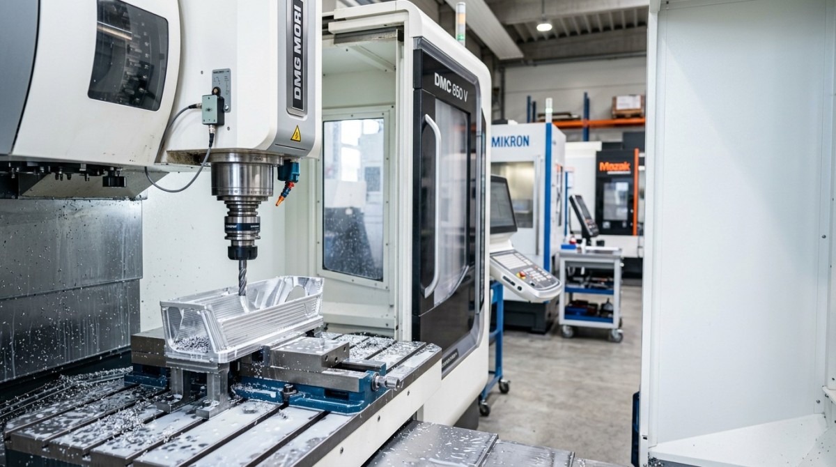
The most common reason unstable peaks appear in CNC milling chatter frequency analysis is that the cutting system is dynamic, not static. A milling process is a closed-loop interaction among spindle, holder, tool, workpiece, fixture, machine structure, and cut geometry. Even when spindle speed remains fixed at 8,000 rpm or 12,000 rpm, slight changes in contact conditions can move dominant vibration energy into a different frequency band.
In regenerative chatter, the waviness left by a previous tooth pass modulates the next cut. If radial immersion changes from 10% to 35%, or axial depth rises from 0.5 mm to 2.0 mm, the phase relationship between vibration and chip thickness can shift quickly. This creates peaks that grow, split, or disappear in the spectrum, especially when the system is operating near a stability boundary.
Another factor is that many shops collect vibration data under non-identical conditions. A signal acquired with one accelerometer position, one sampling rate, or one fixture torque level cannot always be compared directly with a previous run. If the sampling rate changes from 5 kHz to 20 kHz, or the sensor orientation rotates by 30–90 degrees, the apparent spectral profile may change enough to create misleading peak instability.
Tool runout also plays a major role. A cutter with 5–8 μm runout often excites the system differently from one with 15–20 μm runout. That difference alters tooth engagement, force harmonics, and sideband content. In frequency analysis, what looks like an unstable chatter peak may actually be a mix of chatter mode, tooth passing frequency, spindle harmonic content, and intermittent imbalance.
Four primary sources of peak instability
- Dynamic stiffness variation caused by spindle bearing temperature, machine warm-up state, or holder-tool overhang changing by 10–30 mm.
- Cutting-force variation from material lot differences, tool wear progression, coating degradation, or burr formation at the cut edge.
- Boundary condition shifts such as fixture loosening, jaw pressure inconsistency, vacuum clamping loss, or thin-wall deformation.
- Measurement inconsistency including sensor placement, filtering settings, FFT resolution, and aliasing risk in poor data acquisition setups.
For technical benchmarking, unstable peaks should be interpreted as evidence of process sensitivity. In other words, the process may only be stable within a narrow operating window. Shops that can document frequency stability across 3–5 repeated runs, multiple tool lives, and different workholding states usually demonstrate stronger machining control than suppliers that only show one clean spectrum.
How spindle dynamics, tooling, and workpiece rigidity interact
Spindle dynamics are often the first suspect, but they are rarely the only one. A spindle-holder-tool assembly has natural frequencies that can shift under load, thermal expansion, and bearing preload changes. For example, after 20–40 minutes of continuous operation, bearing temperature may rise enough to alter damping behavior. That shift can slightly move resonance zones and change how chatter energy concentrates in a spectrum.
Tool geometry amplifies this effect. A 4-flute end mill with a 3×D overhang behaves very differently from a 2-flute tool with a 5×D overhang. Longer overhang lowers stiffness and often reduces the margin before chatter begins. In many production environments, increasing overhang by only 15 mm can noticeably change the dominant vibration mode and cause peaks to become broader, less repeatable, or more sensitive to feed changes.
Workpiece rigidity is equally important, particularly for thin walls, pockets, ribs, and aerospace-like structures. As material is removed, part stiffness drops. This means chatter frequency analysis taken at the start of a cut may not match the spectrum observed near the end. In thin sections under 3 mm wall thickness, dynamic response can evolve during a single machining cycle, causing moving peaks or transient frequency clusters.
Fixture quality defines the boundary condition. A rigid machine paired with poor clamping can still produce unstable chatter signatures. If clamping torque varies by 10–15%, or unsupported span increases by 20 mm, workpiece modes may become dominant over tool modes. This is why stable chatter analysis depends on the entire machining loop rather than the spindle alone.
Typical dynamic contributors and what they change
The table below summarizes how major mechanical factors influence unstable peaks in CNC milling chatter frequency analysis. It is useful both for troubleshooting and for comparing supplier capability during precision machining audits.
The key takeaway is that unstable peaks are often the signature of interacting modes. A shop that only adjusts spindle speed without checking fixture stiffness, overhang, or runout may suppress one peak while triggering another. For high-precision machining, that is not a true fix; it is only a temporary relocation of the instability.
What operators should check first
- Confirm spindle warm-up state and compare spectra before and after 20–30 minutes of operation.
- Measure tool runout at the cutting edge, not only at the holder nose.
- Review overhang, holder type, and unsupported workpiece length in the exact cutting setup.
- Check whether frequency peaks move during roughing, semi-finishing, and finishing as stiffness changes.
The role of cutting parameters, wear progression, and data acquisition quality
Cutting parameters are often the fastest variables to change and therefore the most visible source of unstable peaks. Spindle speed, feed per tooth, radial width of cut, and axial depth all alter force excitation. A change from 0.03 mm/tooth to 0.08 mm/tooth may increase force amplitude enough to activate a mode that was previously below the detection threshold. The frequency did not necessarily “appear” out of nowhere; the system simply started exciting it more strongly.
Tool wear makes this more complicated. As flank wear grows from a low state to around 0.10–0.20 mm, edge sharpness decreases, friction rises, and thermal load increases. The resulting force spectrum broadens. Instead of one clean chatter peak, analysts may see a cluster of nearby peaks, intermittent harmonics, or amplitude modulation. This is especially common in difficult alloys where heat and adhesion alter the cut dynamically.
Micro machining tolerance limits also matter. In tight-tolerance features, even slight edge chipping or built-up edge can affect tool engagement enough to move a peak. If the feature tolerance is within ±0.01 mm or the surface requirement is below Ra 0.8 μm, small changes in force or runout become highly visible in the vibration record. This is why chatter monitoring becomes more valuable as tolerance and finish requirements tighten.
Data acquisition quality is frequently underestimated. If FFT resolution is too coarse, a moving peak may simply be a resolution artifact. If anti-alias filtering is poor, high-frequency energy can fold into lower bands. If the accelerometer is mounted on a flexible cover instead of a rigid structure, the measured spectrum may include sensor-mount resonance rather than machine-tool vibration. Good analysis requires repeatable sampling conditions, not just more data.
Parameter and measurement issues that commonly distort chatter analysis
The following comparison helps distinguish real process instability from poor test discipline. It is useful for internal process engineers and for buyers evaluating whether a supplier’s vibration report is technically credible.
A robust chatter study should compare at least 3 repeated runs under identical conditions and, where possible, include fresh and worn tools. Without that discipline, unstable peaks may reflect test inconsistency more than machining instability. For procurement and supplier qualification, this difference is critical because it separates real process capability from presentation-quality data.
How to diagnose unstable peaks systematically in production and supplier audits
A practical diagnosis process should begin with isolation, not adjustment. Many teams change speed, feed, and tooling all at once, then lose the ability to identify what caused the spectral change. A better method is to keep 3 variables fixed and change 1 variable at a time. In most shops, a 5-step diagnostic sequence can reveal whether the unstable peak is driven mainly by structure, cutting force, wear, or measurement error.
For internal production, start with the baseline condition that produced acceptable parts. Then repeat the same operation with controlled changes: one test with reduced overhang, one with fresh tooling, one with lower axial depth, and one with a different clamp condition. If the peak disappears only when overhang drops, the issue is probably stiffness-related. If the peak disappears only with a fresh tool, wear is the likely root cause.
For supplier audits, the objective is different. Buyers are less interested in one optimized demonstration cut and more interested in process repeatability. Ask for frequency analysis across at least 2 material states, 2 tool-life stages, and 3 repeated cuts. Also request information on fixture strategy, part-support design, and sensor location. A technically mature supplier should be able to explain not only the measured peak, but why it remains stable within a defined operating window.
This method aligns with a data-first procurement philosophy. Instead of generic quality claims, decision-makers can compare process evidence: frequency repeatability, peak amplitude growth with wear, and the stability limit of a toolpath under known conditions. These are stronger indicators of manufacturing truth than broad statements about capability.
A 5-step troubleshooting workflow
- Verify measurement consistency: same sensor position, same sample rate, same filtering, same workholding.
- Record mechanical condition: spindle warm-up time, holder type, overhang, runout, and fixture torque.
- Separate fresh-tool and worn-tool tests to identify wear-driven spectral changes.
- Vary one parameter at a time, such as spindle speed in 5–10% increments, while keeping the rest fixed.
- Correlate vibration peaks with part outcomes such as surface waviness, size drift, burr formation, and tool life.
Supplier evaluation checklist for buyers and CTOs
- Can the supplier document chatter behavior across different batch sizes, not only one sample part?
- Do they report tolerance hold, roughness, and vibration data together rather than as isolated metrics?
- Can they explain the machine-tool-fixture interaction in technical terms instead of general quality language?
- Do they show process limits, such as safe depth-of-cut windows, instead of implying every condition is stable?
When unstable peaks are diagnosed systematically, the result is not only lower chatter risk. It also improves RFQ quality, clarifies spec sheet requirements, and shortens supplier qualification cycles. That is particularly important in high-value sectors where one unstable process can delay first article approval or drive hidden rework costs across 2–4 production iterations.
What stable chatter analysis means for process control, procurement, and long-term benchmarking
Stable chatter frequency analysis is more than a troubleshooting tool. It is a measurable indicator of process maturity. When a machining partner can maintain consistent spectral behavior, predictable surface finish, and controlled wear response across repeated runs, that usually signals disciplined setup control, better fixture design, and stronger operator-method standardization. In B2B sourcing, those traits are directly linked to lower qualification risk.
For process teams, the objective should be to define a documented stability envelope. That envelope can include spindle speed bands, maximum axial depth, recommended overhang limits, acceptable runout, and wear replacement thresholds. For example, a stable window might specify 9,500–10,200 rpm, axial depth below 1.2 mm, and runout under 10 μm for a specific thin-wall aluminum feature. Such a window gives operators practical control, not just theory.
For procurement and executive teams, the value is comparability. If two suppliers quote the same tolerance, but only one can provide frequency stability data across three repeated cuts and two tool-life stages, that supplier typically offers lower execution uncertainty. Stable frequency behavior does not guarantee perfect output, but unstable and unexplained peaks are often early warnings of hidden process variation.
This is where data-driven benchmarking matters. In advanced manufacturing, parameters carry more weight than adjectives. A vendor that can explain why a chatter peak shifts, what threshold triggers intervention, and how the process remains within tolerance under changing tool life is better positioned to support critical machining programs than one relying on generic capability claims.
Recommended benchmark metrics for machining reviews
In environments where supply chains are judged by measurable engineering performance, this benchmark approach supports smarter sourcing and stronger process control. It reduces trial-and-error, improves technical communication between engineering and procurement, and helps define whether a supplier can truly support demanding production programs.
Frequently asked technical questions
Can unstable peaks exist even when surface finish looks acceptable?
Yes. Early-stage chatter or mode coupling can appear in the spectrum before visible finish damage becomes severe. This is common in roughing operations or in stiffer parts where the process remains dimensionally acceptable for a short period. Monitoring the trend can prevent later degradation in tool life or dimensional stability.
Does changing spindle speed always solve unstable chatter peaks?
No. Changing speed may move the excitation away from one unstable zone, but if the root cause is long overhang, weak fixturing, or worn tooling, another peak may emerge. Speed optimization works best when mechanical and measurement conditions are already controlled.
What should buyers request from a supplier discussing chatter performance?
Request test conditions, tool setup data, runout values, repeated-run spectra, wear-stage comparison, and part-quality correlation. A credible report should explain the process window and its limits, not just present a single attractive graph.
Unstable peaks in CNC milling chatter frequency analysis are a signal worth taking seriously because they often expose the real condition of a machining process: its stiffness, wear sensitivity, setup discipline, and tolerance margin. For engineers, operators, procurement teams, and decision-makers, the goal is not merely to suppress one visible peak, but to understand the system interactions that create it and to define a stable, repeatable operating window.
TechStat Vanguard focuses on this kind of engineering-first interpretation: separating measurable machining truth from vague capability claims. If you are evaluating suppliers, refining a high-precision process, or building a stronger benchmark framework for CNC milling performance, now is the right time to compare data, clarify stability limits, and turn vibration signals into procurement-grade insight. Contact us to discuss your machining benchmark needs, request a tailored evaluation framework, or explore more data-driven hard-tech solutions.
Search News
Hot Articles
- Carbon Fiber StructuresHow to Specify Aerospace Carbon Fiber Assemblies for Lightweight, Load-Bearing PartsJul 11, 2026
- Machine VisionXiaomi, Alibaba DAMO Academy Drive Open-Source Robotics Model Ecosystem, Lowering Algorithm Development Barriers for Overseas SMEs Adopting Chinese Robotics SolutionsMar 30, 2026
- Cobots & ArmsShanxi 'AI+' Conference Showcases Embodied Intelligence with Multinational Buyer Engagement: Key Industry ImplicationsMar 30, 2026
Popular Tags
Recommended News
 Jul 11, 2026How to Specify Aerospace Carbon Fiber Assemblies for Lightweight, Load-Bearing PartsAerospace carbon fiber assemblies: learn how to specify laminate design, load data, joining methods, and inspection controls for lighter, reliable load-bearing aerospace parts.Elena Rostova (UAV Systems Researcher)
 Mar 30, 2026Xiaomi, Alibaba DAMO Academy Drive Open-Source Robotics Model Ecosystem, Lowering Algorithm Development Barriers for Overseas SMEs Adopting Chinese Robotics SolutionsXiaomi & Alibaba DAMO Academy's open-source robotics models lower algorithm barriers for global SMEs. Boost efficiency in manufacturing, logistics & smart retail with ROS 2 compatible solutions.TSV Data Lab
 Mar 30, 2026Shanxi 'AI+' Conference Showcases Embodied Intelligence with Multinational Buyer Engagement: Key Industry ImplicationsShanxi 'AI+' Conference highlights embodied intelligence with Tesla, Ubtech & Jiantao showcasing multimodal robotics. 40+ global buyers validated tech on-site, creating new B2B channels for industrial automation & AI solutions.Chen Wei (Automation Lead Engineer)
 Mar 30, 2026Zhongguancun Unveils 6G Integrated Sensing-Computing-Intelligence Platform to Empower Embodied Robots for Global Industrial ApplicationsZhongguancun's new 6G platform revolutionizes industrial robotics with <10ms latency, empowering global automotive, logistics & port automation. Discover how this tech boosts China's smart manufacturing exports.TSV Data Lab
 Mar 30, 2026Mech-Mind Tianjin Embodied Intelligence R&D and Production Base Goes Live, Cutting Delivery Time by 20%–30% for Global Customized AMR+Vision SolutionsMech-Mind's Tianjin AMR+Vision production base cuts delivery time by 20%-30% for欧美 & Latin American markets. Discover how this PLd-certified facility accelerates customized robotics solutions for smart manufacturing and logistics.Chen Wei (Automation Lead Engineer)
 Mar 30, 2026Boao Forum Reveals 'Co-evolution of Big and Small Brains' Trend in Humanoid Robots, China's Embodied Intelligence Accelerates Adaptation to Overseas Manufacturing Service ScenariosDiscover how China's humanoid robots, featuring 'Co-evolution of Big and Small Brains,' are revolutionizing global manufacturing. Learn about Embodied Tian Gong 3.0's ISO compliance and overseas deployment at Boao Forum 2026.Chen Wei (Automation Lead Engineer)
 Mar 30, 2026China Railway Industrial Secures Patent for Embodied Robotics in Material Handling, Boosting High-Precision Delivery Capabilities for Overseas Infrastructure and Manufacturing ProjectsChina Railway Industrial's new patent for embodied robotics in material handling boosts high-precision delivery for global infrastructure & manufacturing. Discover how this innovation enhances logistics accuracy in automotive, rail transit & EPC projects.Chen Wei (Automation Lead Engineer)
 Oct 27, 2026GXO and Agility Robotics Expand Partnership to Accelerate US Humanoid Robot DeploymentGXO and Agility Robotics plan to expand US humanoid robot deployment with Digit 4 in early 2027. Explore warehouse automation plans, service terms and future Digit 5 upgrades.Chen Wei (Automation Lead Engineer)
 Oct 27, 2026Robotic Automation Costs: Budgeting for Equipment, Integration, and MaintenancePlan your robotics automation cost with confidence. Explore equipment, integration, and maintenance expenses, compare quotes, and build a realistic budget for better ROI.Chen Wei (Automation Lead Engineer)
 Oct 26, 2026AMAXiMAL Releases Open-Source TopMod 3D v3 With Claude AIExplore AMAXiMAL’s free, open-source TopMod 3D v3 with Claude AI assistance, topology-based modeling and plywood fabrication tools that connect complex designs to physical builds.Dr. Marcus Vance
 Oct 26, 2026Choosing a SCADA System Integrator Company: PLC Compatibility and Long-Term SupportChoose a scada system integrator company with proven PLC compatibility and reliable long-term support. Discover what to test, compare, and require before investing.Victor Lin (Chief Software Architect)
 Oct 25, 2026Hesai Leads Global ADAS Main Lidar Shipments in Yole’s 2026 ReportHesai led global ADAS main lidar shipments with a 43% share in 2025, according to Yole’s 2026 report. Explore what this ranking reveals about its automotive market position.TSV Data Lab
 Oct 25, 2026Choosing an Aerospace Materials Manufacturer: Quality and Traceability ChecksChoosing an aerospace materials manufacturer? Learn how to verify certifications, test reports, and lot traceability to qualify suppliers confidently and reduce costly sourcing risks.Dr. Marcus Vance
 Oct 24, 2026Guotai Haitong: Global Entry-Level 3D Printer Shipments Rose 39% in Q1 2026Entry-level 3D printer shipments rose 39% in Q1 2026, Guotai Haitong reports. Explore how AI, multicolor printing and print farms are shaping market growth.Dr. Marcus Vance
 Oct 24, 2026Choosing an Industrial Vision Inspection Supplier: Acceptance Tests That MatterChoose an industrial vision inspection supplier with confidence. Discover acceptance tests for defect detection, false rejects, production speed, and reliable part rejection before you buy.TSV Data Lab
 Oct 23, 2026US Navy Raises Gecko Robotics Contract Ceiling to $300M for Robotic Fleet MaintenanceUS Navy raises Gecko Robotics’ contract ceiling to $300M for Pacific Fleet robotic inspections. Explore potential opportunities for maintenance suppliers and key procurement considerations.Chen Wei (Automation Lead Engineer)
 Oct 23, 2026Choosing Industrial Sensing Systems for Global Plants: Protocol CompatibilityCompare industrial sensing systems international buyers can trust. Explore protocol compatibility, reduce integration risks, and select proven configurations for reliable global plant deployments.TSV Data Lab
 Oct 22, 2026KUKA Showcases Physical AI and iiQKA.AI Vision at NVIDIA GTC BerlinExplore KUKA’s Physical AI showcase at NVIDIA GTC Berlin and discover how iiQKA.AI Vision aims to simplify robotic vision integration and improve 2D and 3D scene recognition.TSV Data Lab
 Oct 22, 2026Robotic Machining of Advanced Composites: What Tolerances Are Achievable?Explore advanced materials machining robotics: discover what drives achievable composite tolerances and how to validate accuracy before investing in your next machining system.Dr. Marcus Vance
 Oct 21, 2026China’s Industrial Robot Exports Near RMB 10 Billion in First Nine Months of 2026China’s industrial robot exports neared RMB 10 billion in January–September 2026, with value rising faster than volume. Explore the data and what it could mean for suppliers.Chen Wei (Automation Lead Engineer)
 Oct 21, 2026Low-Latency Industrial Data Processing: Pricing and Key Cost DriversExplore industrial data latency price drivers, from edge hardware to integration and support. Learn how to compare quotes, verify performance, and avoid unnecessary costs.TSV Data Lab
 Oct 20, 2026KUKA Launches iiQKA.AI Vision to Simplify Industrial Image ProcessingKUKA iiQKA.AI Vision simplifies industrial image processing with controller-based 2D and 3D vision. Explore drag-and-drop setup for vision-guided automation.TSV Data Lab
 Oct 20, 2026Smart Industrial Edge Devices: Key Criteria for Legacy PLC IntegrationChoose smart industrial edge devices for legacy PLC integration. Discover key criteria for compatibility, data quality, security, and reliable collection without disrupting control.TSV Data Lab
 Oct 19, 2026Choosing a Radar Sensor by Application: Range, Resolution, and Field of ViewSimplify radar sensor application based product selection. Compare range, resolution, and field of view to avoid blind spots and choose with confidence. Explore the guide.TSV Data Lab