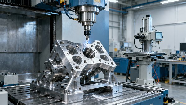
Servo Motor Torque Curve Analysis Helps Catch Sizing Errors Early
Publication Date
author
Servo motor torque curve analysis is one of the fastest ways to uncover undersized drives, hidden overload risks, and unstable motion before they affect uptime. For teams comparing smart factory automation solutions, cobot for cnc machine tending setups, or amr for warehouse logistics projects, understanding real torque behavior helps connect specification sheets to actual operating demands—and supports better engineering, sourcing, and investment decisions.
In hard-tech procurement, the biggest mistake is often not a missing feature but a misunderstood load profile. A servo system that looks adequate on paper may fail when acceleration peaks, duty cycles, or reflected inertia rise above the nominal design window. That gap between rated torque and real application torque is where sizing errors begin to damage cycle time, repeatability, and maintenance cost.
For R&D engineers, operators, sourcing managers, and enterprise decision-makers, torque curve analysis offers a practical filter against vague marketing claims. It turns motion control selection into a measurable engineering exercise. In the data-first philosophy championed by TechStat Vanguard, this matters because servo performance should be judged by verifiable operating behavior, not by generic labels such as “high efficiency” or “industrial grade.”
Why Torque Curve Analysis Matters Before Commissioning
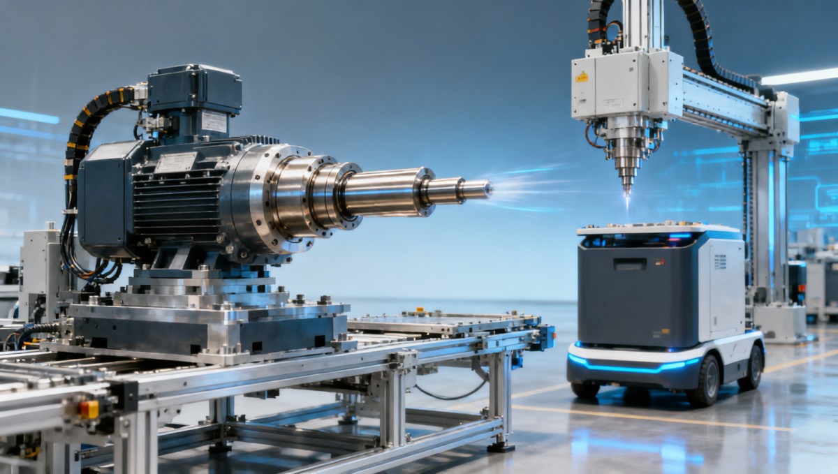
A servo motor torque curve shows how much torque a motor can produce across different speeds, and that relationship is rarely flat. In most industrial applications, continuous torque, peak torque, base speed, and thermal limits all interact. If a machine axis needs 2.5 Nm continuously at 1,500 rpm but the selected motor can only sustain that level for short intervals, the result may be overheating within 20 to 40 minutes of production.
This is especially important in robotics and automation cells where motion is repetitive but not constant. A cobot for CNC machine tending may make 8 to 15 pick-and-place cycles per minute, while an AMR transfer module may accelerate and decelerate dozens of times per hour. In both cases, average load can appear modest, yet short peak demands may exceed 250% to 300% of rated torque, pushing a marginally sized servo into fault-prone territory.
Torque curve analysis is also valuable during supplier comparison. Two servo packages with similar power ratings, such as 750 W or 1.5 kW, may behave very differently above 2,000 rpm or under repeated overload. Procurement teams that only compare list price and nominal power often miss the impact of continuous thermal capacity, allowable overload duration, and matching drive current capability.
For operations teams, early curve analysis reduces commissioning delays. A servo mismatch often appears first as nuisance alarms, inconsistent settle time, or a need to derate acceleration. Those are not just tuning issues. They can indicate that the motor-drive combination is operating outside the practical envelope defined by the torque-speed curve.
What the curve reveals beyond rated power
Rated power alone cannot capture the full motion requirement. A 1 kW servo running a short-index conveyor may succeed, while the same rating may fail on a vertical axis with frequent starts, high reflected inertia, and a braking duty every 3 to 5 seconds. The torque curve helps engineers see whether the application stays within continuous limits, enters short peak zones, or repeatedly crosses thermal boundaries.
- Continuous torque indicates what the motor can sustain without exceeding thermal design limits.
- Peak torque shows the short-duration reserve available for acceleration, impact loads, or transient disturbances.
- Speed-dependent torque reduction highlights where performance falls as rpm rises.
- Drive current limits determine whether the motor can actually reach the advertised peak region in practice.
Common Sizing Errors Found Through Servo Motor Torque Curve Review
One common error is using static load estimates for dynamic systems. A designer may calculate the torque needed to hold a payload of 20 kg, but overlook acceleration torque, friction variation, gearbox efficiency loss, and emergency stop recovery. In machine tending, palletizing, and gantry movement, dynamic torque can be 1.5 to 3 times higher than holding torque, especially where cycle time targets are aggressive.
A second error is confusing peak torque with usable production torque. Many servo motors can deliver peak output for only a few seconds, and some applications exceed that duration in real work. If a vertical lift axis requires 180% torque for 8 seconds but the selected motor supports that overload for just 3 seconds, the design may still pass a light test run yet fail during full-shift operation.
A third issue is underestimating reflected inertia. When load inertia is too high relative to rotor inertia, motion becomes difficult to tune, settling time increases, and current spikes become more severe. In practical automation projects, many teams aim for an inertia ratio in the range of 3:1 to 10:1, though exact tolerance depends on control loop design and mechanical stiffness.
The table below shows how common sizing mistakes translate into production risks across automation scenarios.
The practical lesson is simple: most servo sizing errors are not obvious from a datasheet headline. They emerge when speed, load, duty cycle, and thermal limits are plotted together. That is why torque curve review should happen before RFQ finalization, not after installation.
Where buyers and engineers often misread supplier data
Supplier documentation may present rated torque at one reference condition, such as 25°C ambient, ideal cooling, or a specified drive pair. But factory conditions can involve 35°C to 45°C enclosures, multi-axis cabinets, and longer cable runs. Those conditions may lower practical thermal headroom. For procurement teams, asking for derating guidance under actual installation conditions is often more valuable than asking for promotional feature lists.
How to Read a Torque Curve in Real Automation Scenarios
Reading a servo motor torque curve correctly means translating a graph into a production duty profile. Start with four application values: required continuous torque, peak torque during acceleration, target operating speed, and duty cycle per minute or per hour. Without those four inputs, a curve remains just a picture instead of a decision tool.
In a cobot for CNC machine tending application, for example, the axis may accelerate a gripper and raw part from 0 to operating speed in less than 0.4 seconds. The torque demand spikes at the start, drops during travel, and rises again during stop-and-place phases. If engineers only consider average power, they may underspecify the motor by 20% to 40% even though the line appears to run correctly during initial low-throughput testing.
In an AMR for warehouse logistics project, wheel drive servos experience repeated short bursts during route corrections, ramps, and obstacle avoidance. Torque demand is shaped not only by payload mass, often 100 kg to 1,000 kg depending on platform class, but also by floor friction, wheel diameter, and acceleration policy. That makes torque curve analysis essential when comparing mobility modules from different vendors.
The following framework can help technical and commercial teams review the same torque data using a shared decision language.
A 5-step reading method
- Define the load case, including payload, moving mass, gear ratio, and friction assumptions.
- Plot the speed range, such as 0 to 3,000 rpm, against each motion segment in the cycle.
- Separate continuous torque demand from peak torque bursts and measure the burst duration.
- Verify that the drive can deliver the required current for the motor’s usable peak zone.
- Check thermal repetition over a full shift, not just a 2-minute or 5-minute demonstration cycle.
Typical interpretation ranges
As a practical rule, if the application’s steady-state requirement sits above 80% to 85% of continuous torque, there is limited room for ambient variation, friction growth, or payload drift. If peak events regularly exceed 70% of the allowable overload duration, the design may work but carry elevated fault risk. These are not universal thresholds, yet they are useful screening ranges in early-stage engineering review.
Teams should also compare the commanded acceleration to the mechanical compliance of the system. A high-torque motor can still behave poorly if coupling stiffness, gearbox backlash, or frame resonance distort the effective demand seen by the servo loop. In that sense, torque curve analysis should be paired with mechanical system review rather than treated as an isolated motor exercise.
Key Parameters to Compare During Sourcing and Technical Evaluation
When procurement enters the evaluation phase, torque curve analysis should become a comparison framework, not just an engineering check. The best sourcing decisions combine performance envelope, control compatibility, thermal margin, and lifecycle serviceability. This is especially relevant in cross-border supply chains where replacement lead time can range from 2 weeks for stocked models to 10 to 16 weeks for less common configurations.
For enterprise buyers, the goal is not to buy the biggest servo, but the right servo with measurable reserve. Oversizing by a large margin can increase cost, cabinet size, and inertia mismatch. Undersizing creates downtime risk. A practical target is a balanced margin where continuous production stays inside the stable operating region and transient loads remain inside the proven overload window.
The table below can be used during RFQ review, supplier meetings, or internal design gate approval.
This comparison approach is aligned with data-driven industrial sourcing. It helps buyers connect motion performance to production continuity, maintenance planning, and total installed cost rather than making decisions from list price alone.
Useful commercial checkpoints
- Ask whether the torque curve is based on natural cooling or forced cooling, because this can materially affect continuous output.
- Confirm spare part availability for at least 24 to 36 months if the machine is intended for global deployment.
- Check whether supplier commissioning support covers load validation, not only parameter download and basic servo enablement.
- Request recommended safety margin ranges for high-cycle applications above 10,000 starts per day.
Implementation, Risk Control, and Frequently Asked Questions
A strong servo sizing decision is only complete when the torque curve is validated in operation. That means collecting current, speed, thermal, and fault data during pilot production. In many facilities, the most useful validation window is the first 24 to 72 hours of realistic duty rather than a short functional acceptance test. This is where hidden overload exposure, repeated saturation, or deceleration instability usually becomes visible.
Risk control should include both engineering and procurement actions. Engineering teams should document assumptions on payload variation, motion profile, and ambient conditions. Procurement teams should ensure that the quotation and technical attachment include the exact drive pairing, cable set, brake option if relevant, and commissioning scope. Small specification gaps at order stage can become expensive retrofit problems later.
For organizations following a benchmark-driven sourcing model, torque curve analysis also supports supplier qualification. Vendors that provide transparent operating envelopes, derating guidance, and application review data are easier to validate than vendors offering only broad claims. This fits the TSV principle that industrial decisions should be anchored in parameters, tolerances, and traceable technical logic.
Risk control checklist
- Validate torque demand with a full motion cycle, including worst-case payload and maximum acceleration.
- Confirm overload duration and recovery intervals instead of relying on a single peak torque number.
- Measure cabinet temperature during trial runs; a 10°C increase can materially reduce thermal margin.
- Review braking and vertical holding requirements if the axis can drop or back-drive during power loss.
- Document acceptable current utilization bands and alarm thresholds before handover to operations.
How much safety margin is usually reasonable?
For many industrial servo applications, teams aim to keep normal continuous demand below roughly 70% to 85% of continuous torque, depending on ambient temperature, cycle intensity, and maintenance philosophy. High-dynamic systems may require a more conservative margin if downtime cost is high or if the installation environment is thermally constrained.
Can tuning fix an undersized servo motor?
Tuning can reduce overshoot, improve response, and sometimes smooth current spikes, but it cannot create missing thermal capacity or sustained torque. If the motor-drive package lacks sufficient continuous or overload capability, tuning only delays the symptom. The underlying sizing gap remains.
When should torque curve analysis be done in the buying cycle?
The best time is before final supplier selection and before machine layout is frozen. Early review avoids redesign of gear ratios, cabinet thermal management, and braking hardware. In projects with 6 to 12 week procurement windows, reviewing the torque curve during RFQ or technical clarification can save substantial rework later.
Servo motor torque curve analysis is not just a motion-control detail. It is an early-warning tool for undersized systems, unstable production behavior, and avoidable sourcing mistakes. By checking continuous torque, peak duration, speed-dependent output, thermal derating, and drive pairing together, engineering and procurement teams gain a more reliable basis for automation decisions.
For organizations evaluating robotics, AMR platforms, CNC tending cells, or other data-driven industrial upgrades, a parameter-first review process reduces trial-and-error cost and shortens supplier qualification time. If you want a clearer benchmark for servo selection, application risk screening, or technical sourcing support, contact us to discuss your operating profile, compare solution paths, and get a more precise motion-control evaluation.
Search News
Hot Articles
- Carbon Fiber StructuresHow to Specify Aerospace Carbon Fiber Assemblies for Lightweight, Load-Bearing PartsJul 11, 2026
- Machine VisionXiaomi, Alibaba DAMO Academy Drive Open-Source Robotics Model Ecosystem, Lowering Algorithm Development Barriers for Overseas SMEs Adopting Chinese Robotics SolutionsMar 30, 2026
- Cobots & ArmsShanxi 'AI+' Conference Showcases Embodied Intelligence with Multinational Buyer Engagement: Key Industry ImplicationsMar 30, 2026
Popular Tags
Recommended News
 Jul 11, 2026How to Specify Aerospace Carbon Fiber Assemblies for Lightweight, Load-Bearing PartsAerospace carbon fiber assemblies: learn how to specify laminate design, load data, joining methods, and inspection controls for lighter, reliable load-bearing aerospace parts.Elena Rostova (UAV Systems Researcher)
 Mar 30, 2026Xiaomi, Alibaba DAMO Academy Drive Open-Source Robotics Model Ecosystem, Lowering Algorithm Development Barriers for Overseas SMEs Adopting Chinese Robotics SolutionsXiaomi & Alibaba DAMO Academy's open-source robotics models lower algorithm barriers for global SMEs. Boost efficiency in manufacturing, logistics & smart retail with ROS 2 compatible solutions.TSV Data Lab
 Mar 30, 2026Shanxi 'AI+' Conference Showcases Embodied Intelligence with Multinational Buyer Engagement: Key Industry ImplicationsShanxi 'AI+' Conference highlights embodied intelligence with Tesla, Ubtech & Jiantao showcasing multimodal robotics. 40+ global buyers validated tech on-site, creating new B2B channels for industrial automation & AI solutions.Chen Wei (Automation Lead Engineer)
 Mar 30, 2026Zhongguancun Unveils 6G Integrated Sensing-Computing-Intelligence Platform to Empower Embodied Robots for Global Industrial ApplicationsZhongguancun's new 6G platform revolutionizes industrial robotics with <10ms latency, empowering global automotive, logistics & port automation. Discover how this tech boosts China's smart manufacturing exports.TSV Data Lab
 Mar 30, 2026Mech-Mind Tianjin Embodied Intelligence R&D and Production Base Goes Live, Cutting Delivery Time by 20%–30% for Global Customized AMR+Vision SolutionsMech-Mind's Tianjin AMR+Vision production base cuts delivery time by 20%-30% for欧美 & Latin American markets. Discover how this PLd-certified facility accelerates customized robotics solutions for smart manufacturing and logistics.Chen Wei (Automation Lead Engineer)
 Mar 30, 2026Boao Forum Reveals 'Co-evolution of Big and Small Brains' Trend in Humanoid Robots, China's Embodied Intelligence Accelerates Adaptation to Overseas Manufacturing Service ScenariosDiscover how China's humanoid robots, featuring 'Co-evolution of Big and Small Brains,' are revolutionizing global manufacturing. Learn about Embodied Tian Gong 3.0's ISO compliance and overseas deployment at Boao Forum 2026.Chen Wei (Automation Lead Engineer)
 Mar 30, 2026China Railway Industrial Secures Patent for Embodied Robotics in Material Handling, Boosting High-Precision Delivery Capabilities for Overseas Infrastructure and Manufacturing ProjectsChina Railway Industrial's new patent for embodied robotics in material handling boosts high-precision delivery for global infrastructure & manufacturing. Discover how this innovation enhances logistics accuracy in automotive, rail transit & EPC projects.Chen Wei (Automation Lead Engineer)
 Oct 15, 2026R&D Cost Reduction Services: How to Evaluate Fees, Savings, and ROIEvaluate R&D cost reduction services with confidence. Compare fees, verify savings, and calculate ROI without compromising performance. Discover how to choose a provider that delivers real value.Chen Wei (Automation Lead Engineer)
 Oct 15, 2026How Should You Compare TechStat Vanguard 5-Axis CNC Tolerances?TechStat Vanguard 5-axis CNC tolerance comparison: learn how to verify part accuracy, assess inspection evidence, and choose suppliers that reliably meet your drawing requirements.Dr. Marcus Vance
 Oct 14, 2026Drone Frame Composites: Carbon Fiber vs. Fiberglass for Weight and StiffnessExplore drone structural materials composites: compare carbon fiber and fiberglass for weight, stiffness, cost, and antenna compatibility. Find the right material for your drone frame.Elena Rostova (UAV Systems Researcher)
 Oct 13, 2026Smart Cameras vs. PC-Based Machine Vision: Which Fits High-Speed Inspection?This industrial product comparison for machine vision weighs smart cameras vs. PC-based systems on latency, throughput, and cost. Discover your best fit for high-speed inspection.TSV Data Lab
 Oct 12, 2026How to Verify RoHS Compliance in Industrial Sensing Systems Before DeploymentRoHS compliant sensing systems: learn how to verify materials, supplier declarations, testing, and configuration controls before industrial deployment.TSV Data Lab
 Oct 11, 2026How Procurement-Oriented Content Taxonomy Improves B2B Buying JourneysProcurement-oriented content taxonomy streamlines B2B buying journeys with clearer evidence, supplier comparisons, risk visibility, and faster approvals.TSV Data Lab
 Oct 10, 2026How to Select a Machine Performance Monitoring Platform for OEE and Downtime ReductionMachine performance monitoring platform selection guide: validate machine states, OEE data, downtime reasons, integrations, and scalability to reduce losses with confidence.TSV Data Lab
 Oct 08, 2026How to Machine Inconel 625 Blades Without Heat Cracks or Edge ChippingInconel 625 blade machining guide: prevent heat cracks, edge chipping, chatter, and work hardening with proven tooling, cooling, fixturing, and inspection strategies.Dr. Marcus Vance
 Oct 07, 2026How to Evaluate an HMI Panel Distributor for Industrial Automation ProjectsHMI panel distributor evaluation guide: verify technical compatibility, traceability, supply reliability, lifecycle support, and total cost for automation projects.Victor Lin (Chief Software Architect)
 Oct 06, 2026Navigation Fault Tolerance Standards for AMRs: What Safety Teams Must VerifyNavigation fault tolerance standards: learn what AMR safety teams must verify, from localization loss and sensor faults to stopping distance, safe restart, and site-specific validation.Chen Wei (Automation Lead Engineer)
 Oct 05, 2026Calculating Edge Computing Total Cost of Ownership Across Distributed SitesEdge computing ownership cost explained: calculate deployment, energy, connectivity, security, remote support, and refresh costs across distributed sites.TSV Data Lab
 Oct 04, 2026CAD/CAM Benchmarking in the GCC: What Manufacturers Should Ask a ConsultantCAD CAM benchmark consultant GCC guide: learn the key questions manufacturers should ask to validate post-processors, workflows, machine performance, and production risk.Victor Lin (Chief Software Architect)
 Oct 03, 2026Selecting Automotive Radar Sensor Modules for ADAS Range, Resolution, and IntegrationAutomotive radar sensor module selection guide for ADAS: compare range, resolution, field of view, latency, and integration to build safer, reliable vehicle systems.TSV Data Lab
 Oct 02, 2026How to Qualify Machined Parts Suppliers for Hard Tech ProgramsHard tech supply chain machined parts demand rigorous supplier qualification. Learn how to assess capability, traceability, quality controls, and delivery resilience.Dr. Marcus Vance
 Oct 01, 2026How to Select an Outdoor Security Radar Sensor for Perimeter Detection?Outdoor security radar sensor selection guide: compare range, accuracy, false-alarm control, integration, and field testing for reliable perimeter detection.TSV Data Lab
 Sep 30, 2026How to Evaluate Solid-State LiDAR Hardware for Outdoor Autonomous VehiclesSolid state LiDAR hardware evaluation guide for outdoor autonomous vehicles—compare range, point-cloud quality, environmental resilience, integration, and safety.TSV Data Lab
 Sep 29, 2026ISO 9283 Repeatability: How to Evaluate Cobot Positioning PerformanceISO 9283 cobot repeatability explained: learn how payload, reach, approach direction, and test conditions affect positioning performance and cell capability.Chen Wei (Automation Lead Engineer)