
What Limits Industrial Robots in Welding Thin Materials?
Publication Date
author
When welding thin materials, even advanced industrial robots for welding applications face hard limits in heat control, joint fit-up, distortion management, and sensor response. For operators, these constraints directly affect bead quality, burn-through risk, and rework rates. This article breaks down the real engineering factors behind those limits, helping you understand where robot performance ends and process discipline begins.
Why do industrial robots for welding applications struggle with thin materials?
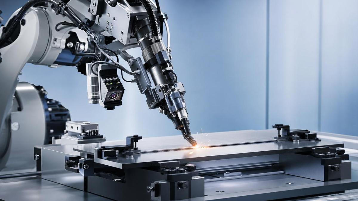
Thin-gauge welding looks simple until the heat source, fixture, wire feed, and part variation all begin interacting in milliseconds. In practice, industrial robots for welding applications are highly repeatable, but repeatability is not the same as adaptability. A robot can move to the same programmed point every cycle and still produce unstable welds if the sheet thickness varies, the gap opens slightly, or the edge condition changes.
Operators often expect the robot to “solve” inconsistency. That expectation creates frustration on the shop floor. The real limit is that robotic welding systems obey physics first, software second, and operator setup third. On thin stainless steel, aluminum, galvanized sheet, or low-carbon steel, tiny changes in heat input can shift the result from full fusion to burn-through in a very short window.
For TechStat Vanguard, the useful question is not whether robotic welding is advanced. The useful question is which parameter is governing failure. Is it arc stability, fixture rigidity, travel speed, torch angle, seam tracking latency, or edge quality? Once operators learn to isolate the limiting variable, robotic welding cells become more predictable and less dependent on trial-and-error adjustments.
- Thin materials store less thermal mass, so temperature rises too quickly and the burn-through threshold is reached faster.
- Joint gaps that seem minor in fabrication can exceed the process window of the weld schedule.
- Robot path accuracy cannot compensate for poor fixturing, warped blanks, or inconsistent tack positions.
- Sensors help, but sensor feedback still has resolution limits, noise sensitivity, and response delay.
What are the real engineering limits operators should watch first?
The table below maps the most common limiting factors in industrial robots for welding applications when processing thin materials. This is the level of information operators actually need during setup, troubleshooting, and daily production handoff.
The key reading is that most failures are not caused by the robot arm alone. They come from a chain of tolerances. TSV’s engineering view is simple: parameters do not lie. If the sheet, gap, fixture, and wire process are not held inside a narrow tolerance band, the robot repeats a bad condition very efficiently.
Heat input is usually the first hard limit
On thin materials, operators have less room to correct with amperage or voltage changes alone. Travel speed, pulse behavior, wire diameter, arc length, and stick-out all interact. A schedule that looks safe on one batch can fail on the next if surface coating, gap size, or thermal contact to the fixture changes. This is why industrial robots for welding applications must be tuned as a system, not as a motion device only.
Fit-up errors are amplified in robotic cells
A skilled manual welder can visually compensate for a changing gap or a pulled edge in real time. A robot depends on programmed geometry plus available feedback. On thin sheet, even a modest fit-up shift can push the weld outside the acceptable fusion window. This is one reason cells that run well on rigid parts often struggle when transferred to lighter-gauge assemblies.
Which thin-material welding scenarios are hardest for robotic systems?
Not every application stresses industrial robots for welding applications in the same way. Operators should separate “robot-friendly” thin-sheet jobs from “high-risk” ones before blaming the equipment. The next table helps compare typical scenarios seen across general industry fabrication lines.
The hardest jobs combine three conditions: low thermal mass, variable fit-up, and long seams. If your operation includes all three, the robot cell needs stronger process discipline than a heavy-section MIG job. That means better fixtures, cleaner incoming parts, tighter operator checks, and realistic expectations about cycle time.
Can sensors and adaptive control remove these limits?
Sensors reduce risk, but they do not erase process boundaries. Laser seam tracking, through-arc sensing, touch sensing, and vision guidance can help industrial robots for welding applications recover from moderate variation. However, each method has a response envelope. If a part moves too much, reflects too strongly, or presents inconsistent edge geometry, the sensing system may provide unstable corrections or no reliable correction at all.
Operators should treat sensing as a compensation layer, not a substitute for fit-up control. A common mistake is adding seam tracking to a poor fixture and expecting stable output. In reality, the robot may chase a distorted seam while the arc process still exceeds the acceptable heat window. The result is a tracked defect instead of an untracked defect.
Where adaptive control helps most
- Recovering from small positional shifts between nominally identical parts.
- Correcting torch approach on joints where manual loading creates slight offset.
- Stabilizing start points and improving repeatability across long production runs.
Where adaptive control still reaches a limit
- Large or rapidly changing root gaps that require a fundamentally different weld schedule.
- Highly reflective or contaminated surfaces that degrade optical sensing quality.
- Distortion that develops during the weld faster than the control loop can react.
This is where TSV’s data-driven mindset matters. Instead of asking whether a sensor is “smart,” ask for measurable values: sensing resolution, correction frequency, allowable seam variation, and the operating conditions under which those numbers remain valid.
How should operators set up industrial robots for welding applications on thin sheet?
For operators, stable output starts before the cycle start button. Thin-material robotic welding is won or lost in preparation, not in last-minute parameter rescue. A disciplined setup routine reduces false troubleshooting and makes root causes visible earlier.
- Verify incoming part consistency. Check thickness range, edge condition, coating state, and gap at several points, not just at the start of the seam.
- Confirm fixture repeatability. Look for clamp wear, thermal looseness, and datum contamination that can shift part location by fractions that still matter on thin sheet.
- Lock the weld schedule to a tested process window. Avoid frequent uncontrolled edits by multiple shifts unless each change is documented against a defect symptom.
- Inspect consumables. Contact tip wear, liner condition, shielding gas stability, and wire feed drag can create arc behavior that looks like a robot accuracy issue.
- Run witness pieces when material lot, fixture maintenance state, or ambient conditions change significantly.
Operators also need clear escalation criteria. If defects persist after confirming consumables and fixture condition, the issue may belong to process engineering, not robot programming alone. Separating operator-adjustable variables from engineering-level variables prevents wasted downtime.
What should procurement and production teams compare before selecting a robotic welding solution?
When evaluating industrial robots for welding applications for thin materials, selection errors often come from comparing only arm payload, reach, or headline repeatability. That is too narrow for real production use. The more useful comparison is system capability under thin-material constraints.
This type of comparison supports better procurement decisions and shorter commissioning time. TSV’s value in this stage is practical screening. We help teams cut through marketing language and focus on tolerances, process windows, and verification logic that actually affect production quality.
Which standards and process controls matter most?
For general industry users, thin-material robotic welding should align with established welding procedure control, inspection discipline, and equipment safety practice. Depending on the sector, teams may reference frameworks such as ISO welding quality requirements, welding procedure qualification methods, material-specific fabrication standards, and robot safety integration practices. The exact standard set varies by customer requirement and product category.
What matters operationally is not the logo on a document but the behavior it enforces. Good standards push teams to define acceptance criteria, document parameter windows, maintain traceability, and control changes. On thin sheet, this discipline reduces “mystery defects” that only appear on certain shifts or material lots.
- Use qualified weld procedures where customer contracts or regulated sectors require them.
- Document machine settings, wire type, shielding gas, and fixture status by part family.
- Apply first-off inspection and periodic verification, especially after maintenance or consumable replacement.
- Define clear reject criteria for burn-through, lack of fusion, undercut, distortion, and visual surface condition.
Common misconceptions about industrial robots for welding applications
“Higher robot accuracy will automatically fix thin-sheet defects”
Not by itself. If the seam moves because the part distorts or the gap changes, the better arm still needs a process and sensing strategy that fits the real variation. Accuracy is valuable, but it is only one piece of the chain.
“Once programmed, the cell should run any batch of the same drawing”
Drawings define intent, not actual shop-floor variation. On thin materials, coil differences, stamping springback, coating state, and tack sequence can all shift the weld response. Program stability depends on upstream consistency.
“Sensors make fixturing less important”
Usually the opposite is true. Better sensors reveal how unstable poor fixturing really is. A strong fixture gives sensors a manageable correction task. A weak fixture forces them to compensate beyond their practical range.
FAQ: what do operators and buyers ask most often?
How do I know if thin-material welding is suitable for a robot cell?
Start with part consistency, seam accessibility, and quality tolerance. If the product family has stable geometry, manageable distortion, and repeatable loading, industrial robots for welding applications can work well. If the part changes shape significantly from one piece to another, manual or semi-automated methods may remain more forgiving unless fixturing and sensing are upgraded.
What should I check first when burn-through appears suddenly?
Check part thickness variation, gap growth, clamp contact, wire feed behavior, and actual torch-to-work distance before changing the whole program. Sudden burn-through often points to a physical change in the setup rather than a spontaneous software problem.
Are collaborative robots a better option for thin materials?
That depends on cycle time, reach, safety layout, and required process stability. Cobots can be useful for low-volume, flexible welding tasks, but the thin-material limits remain the same: heat control, fit-up, and distortion do not disappear because the robot category changes.
What data should I request before buying a system?
Ask for demonstrated process capability on similar material thickness, expected seam variation tolerance, sensing method limits, maintenance points, and the assumptions behind quoted cycle time. Requesting this data is far more useful than comparing brochure language.
Why work with TechStat Vanguard before you commit?
TechStat Vanguard exists for teams that need engineering truth, not inflated claims. If you are evaluating industrial robots for welding applications for thin materials, we help translate supplier language into measurable decision criteria. That includes parameter confirmation, process-window review, fixture-risk screening, sensor suitability checks, and comparison logic for competing cell concepts.
You can contact TSV for support on specific technical questions such as material thickness range assessment, weld process selection, delivery-cycle considerations for automation projects, custom benchmark frameworks for supplier comparison, and compliance-oriented documentation needs. If your team needs a more disciplined basis for quotation review, sample evaluation, or line-upgrading decisions, TSV can help you define what should be measured before money is committed and rework costs appear later.
In thin-material robotic welding, performance ends where uncontrolled variation begins. The fastest way to improve outcomes is to measure the right limits, ask the right questions, and build the cell around real tolerances rather than assumptions.
Search News
Hot Articles
- Carbon Fiber StructuresHow to Specify Aerospace Carbon Fiber Assemblies for Lightweight, Load-Bearing PartsJul 11, 2026
- Machine VisionXiaomi, Alibaba DAMO Academy Drive Open-Source Robotics Model Ecosystem, Lowering Algorithm Development Barriers for Overseas SMEs Adopting Chinese Robotics SolutionsMar 30, 2026
- Cobots & ArmsShanxi 'AI+' Conference Showcases Embodied Intelligence with Multinational Buyer Engagement: Key Industry ImplicationsMar 30, 2026
Popular Tags
Recommended News
 Jul 11, 2026How to Specify Aerospace Carbon Fiber Assemblies for Lightweight, Load-Bearing PartsAerospace carbon fiber assemblies: learn how to specify laminate design, load data, joining methods, and inspection controls for lighter, reliable load-bearing aerospace parts.Elena Rostova (UAV Systems Researcher)
 Mar 30, 2026Xiaomi, Alibaba DAMO Academy Drive Open-Source Robotics Model Ecosystem, Lowering Algorithm Development Barriers for Overseas SMEs Adopting Chinese Robotics SolutionsXiaomi & Alibaba DAMO Academy's open-source robotics models lower algorithm barriers for global SMEs. Boost efficiency in manufacturing, logistics & smart retail with ROS 2 compatible solutions.TSV Data Lab
 Mar 30, 2026Shanxi 'AI+' Conference Showcases Embodied Intelligence with Multinational Buyer Engagement: Key Industry ImplicationsShanxi 'AI+' Conference highlights embodied intelligence with Tesla, Ubtech & Jiantao showcasing multimodal robotics. 40+ global buyers validated tech on-site, creating new B2B channels for industrial automation & AI solutions.Chen Wei (Automation Lead Engineer)
 Mar 30, 2026Zhongguancun Unveils 6G Integrated Sensing-Computing-Intelligence Platform to Empower Embodied Robots for Global Industrial ApplicationsZhongguancun's new 6G platform revolutionizes industrial robotics with <10ms latency, empowering global automotive, logistics & port automation. Discover how this tech boosts China's smart manufacturing exports.TSV Data Lab
 Mar 30, 2026Mech-Mind Tianjin Embodied Intelligence R&D and Production Base Goes Live, Cutting Delivery Time by 20%–30% for Global Customized AMR+Vision SolutionsMech-Mind's Tianjin AMR+Vision production base cuts delivery time by 20%-30% for欧美 & Latin American markets. Discover how this PLd-certified facility accelerates customized robotics solutions for smart manufacturing and logistics.Chen Wei (Automation Lead Engineer)
 Mar 30, 2026Boao Forum Reveals 'Co-evolution of Big and Small Brains' Trend in Humanoid Robots, China's Embodied Intelligence Accelerates Adaptation to Overseas Manufacturing Service ScenariosDiscover how China's humanoid robots, featuring 'Co-evolution of Big and Small Brains,' are revolutionizing global manufacturing. Learn about Embodied Tian Gong 3.0's ISO compliance and overseas deployment at Boao Forum 2026.Chen Wei (Automation Lead Engineer)
 Mar 30, 2026China Railway Industrial Secures Patent for Embodied Robotics in Material Handling, Boosting High-Precision Delivery Capabilities for Overseas Infrastructure and Manufacturing ProjectsChina Railway Industrial's new patent for embodied robotics in material handling boosts high-precision delivery for global infrastructure & manufacturing. Discover how this innovation enhances logistics accuracy in automotive, rail transit & EPC projects.Chen Wei (Automation Lead Engineer)
 Sep 29, 2026ISO 9283 Repeatability: How to Evaluate Cobot Positioning PerformanceISO 9283 cobot repeatability explained: learn how payload, reach, approach direction, and test conditions affect positioning performance and cell capability.Chen Wei (Automation Lead Engineer)
 Sep 28, 2026Spindle Runout Measurement in Germany: DIN Standards, Methods, and Acceptance LimitsSpindle runout measurement Germany: explore DIN standards, proven methods, acceptance limits, and audit-ready practices for reliable machining quality.Dr. Marcus Vance
 Sep 27, 2026How to Select Wall-Mount Edge Devices for Space-Constrained Factory NetworksWall mount edge devices for space-constrained factories: evaluate workload, thermal design, power resilience, cable access, and network reliability for smarter deployments.TSV Data Lab
 Sep 26, 2026Machining Tolerance Analysis: How to Set Limits That Meet Function and Cost TargetsMachining tolerance analysis: learn how to set functional limits, control tolerance stacks, reduce inspection risk, and balance precision with production cost.Dr. Marcus Vance
 Sep 25, 2026How to Evaluate an Industrial Infrastructure Data Platform for Multi-Site OperationsIndustrial infrastructure data platform evaluation guide for multi-site operations: compare data quality, edge resilience, interoperability, governance, and scalable proof-of-value criteria.Victor Lin (Chief Software Architect)
 Sep 24, 2026How to Select Machine Vision Optics for Accurate Inspection at Different Working DistancesMachine vision optics selection guide for accurate inspection at every working distance. Compare FOV, pixel scale, DOF, distortion, lighting, and telecentric options.TSV Data Lab
 Sep 23, 2026How to Evaluate a Machine Vision System Integrator for High-Speed Inspection LinesChoose a machine vision system integrator with proven expertise in high-speed inspection, reliable reject timing, robust optics, and measurable acceptance criteria.TSV Data Lab
 Sep 28, 2026When is a SCADA API the right choice for connecting plant systems?SCADA API guide: learn when governed plant data integration improves traceability, security, and scalability—without compromising real-time control.Victor Lin (Chief Software Architect)
 Sep 27, 2026How SCADA data integration improves traceability across production linesSCADA data integration connects production-line data to improve traceability, accelerate quality investigations, and strengthen safety decisions.Victor Lin (Chief Software Architect)
 Sep 26, 2026What to define before starting SCADA integration planningSCADA integration planning starts with clear scope, control boundaries, data models, cybersecurity, and testing. Discover the definitions that reduce risk and costly rework.Victor Lin (Chief Software Architect)
 Sep 25, 2026How a smart factory with Industrial IoT reduces production blind spotsDiscover how a smart factory with Industrial IoT turns real-time machine, quality, and workflow data into actionable insights that reduce production blind spots and delivery risks.Victor Lin (Chief Software Architect)
 Sep 24, 2026When does Industrial IoT make smart manufacturing easier to scale?Smart manufacturing Industrial IoT scales when trusted data, interoperable systems, and secure workflows turn connected assets into measurable gains.TSV Data Lab
 Sep 23, 2026What drives ultra-precision machining cost at 1-micron tolerance?Ultra precision machining cost per part at 1 micron tolerance depends on process, material, metrology, and yield. Learn how to compare quotes confidently.Dr. Marcus Vance
 Sep 22, 2026Drone Engine-T550CC Applications: Build the UAV Power System Around the MissionAn application guide for Drone Engine-T550CC integration, covering payload planning, airframe matching, cooling, fuel, vibration, test procedures, documentation, and service preparation.Elena Rostova (UAV Systems Researcher)
 Sep 22, 2026How to Evaluate Industrial Edge Computing Vendors for Factory DeploymentIndustrial edge computing vendor evaluation guide for factories: compare latency, protocol fit, reliability, security, and lifecycle support before deployment.TSV Data Lab
 Sep 21, 2026Drone Payload Integration: Matching Power, Data, and Center of Gravity for Reliable FlightsDrone payload integration made practical: balance power, data, center of gravity, and endurance to build safer, more reliable mission-ready flights.Elena Rostova (UAV Systems Researcher)
 Sep 20, 2026Autonomous Navigation Pricing: Cost Drivers and Budget Benchmarks for AMR ProjectsAutonomous navigation price explained: compare AMR cost drivers, software, sensors, integration, safety, and lifecycle budgets to build a scalable project plan.Chen Wei (Automation Lead Engineer)























