Welding robot arm price changes fast with safety scope
Publication Date
author
As welding robot arm price shifts rapidly, buyers can no longer evaluate systems on cost alone. Safety scope, cobot collision detection threshold, industrial robot payload vs reach chart, and 6 axis robot calibration methods now shape real procurement value. This guide helps researchers, operators, and decision-makers compare technical benchmarks with clarity, reducing sourcing risk in fast-moving automation markets.
In today’s automation market, pricing can change within one quarter due to controller upgrades, servo supply fluctuations, safety component lead times, and regional compliance demands. A welding cell that looked cost-effective 90 days ago may become less competitive once fencing layout, scanner coverage, torch package wear rate, and integration labor are included. For procurement teams, that means the true comparison point is no longer the arm alone, but the total operating envelope of the system.
For TechStat Vanguard, the useful question is not whether a robotic welding arm is “advanced,” but whether its measurable parameters support stable production. Repeatability, payload derating at extended reach, collision sensitivity, arc start consistency, and calibration drift over 6 to 12 months are the metrics that determine value. This article breaks down those benchmarks in a practical format for information researchers, operators, sourcing teams, and executive decision-makers.
Why welding robot arm prices change faster than many buyers expect
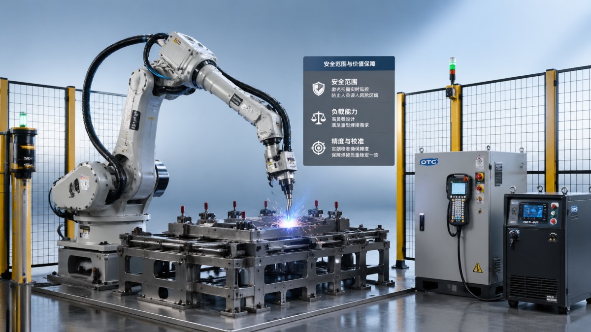
A welding robot arm price is influenced by more than steel structure and servo count. In most industrial sourcing cycles, 4 major variables move cost quickly: payload class, reach length, safety hardware, and software package depth. A 6 kg to 12 kg arm for MIG or TIG welding may sit in one budget band, while a 20 kg to 25 kg arm with extended reach, seam tracking, and offline programming can rise sharply once application modules are added.
Safety scope is one of the most underestimated cost drivers. When buyers compare a basic welding robot to a collaborative welding setup, they often focus on the arm price and overlook area scanners, safety PLCs, interlock logic, speed-and-separation monitoring, and validation time. In many projects, the safety architecture can represent 10% to 25% of the final cell budget, especially when the robot works near operators, fixtures, or mixed manual stations.
Price volatility also comes from integration depth. A standalone arm may have a clear list price, but a production-ready cell includes torch cleaning, wire feeder routing, positioners, extraction interfaces, and fixture communication. If a project requires two-station loading, part identification, or adaptive welding based on vision data, engineering hours can increase by 20 to 40% compared with a standard repetitive welding application.
Another practical factor is regional compliance and installation environment. A robotic system installed in a high-mix fabrication plant with narrow aisles and shared worker access may need more compact guarding and more sophisticated zoning than a cell in a greenfield plant. The same robot arm can therefore generate very different total ownership costs depending on plant layout, floor conditions, ventilation, and line balancing requirements.
Four cost layers buyers should separate during evaluation
- Base robot configuration: arm, controller, teach pendant, standard cable set, and default software.
- Process package: welding power source interface, torch package, wire feeder, seam tracking, and arc monitoring.
- Safety scope: fencing, light curtains, scanners, safety PLC, emergency stops, lockout points, and risk validation.
- Integration and lifecycle support: fixture matching, commissioning, operator training, spare parts planning, and recalibration support.
The table below helps separate fast-changing cost components from those that remain relatively stable across procurement cycles.
The key takeaway is that rapid price movement does not always indicate market instability alone. In many cases, the cost shifts because the defined safety scope or process scope changed. Buyers who request a quote without a clear envelope, duty cycle, and access model often receive numbers that cannot be compared on an equal basis.
How safety scope changes the real value of a welding robot system
Safety scope is not an accessory decision. It is part of the robot system architecture. In welding automation, the chosen safety concept affects throughput, maintenance access, floor utilization, and labor interaction. A fenced industrial robot cell may permit higher travel speed and larger payload usage, while a collaborative setup may reduce guarding but impose lower speeds, stricter force thresholds, and narrower application windows.
For operators, the practical question is whether the robot can stop or slow down at the correct distance without causing nuisance interruptions. For procurement teams, the question is whether that safety envelope supports the takt time. If a plant targets a 45-second to 90-second weld cycle, scanner zone switching, reset logic, and part loading sequence must be engineered so the system remains productive rather than merely compliant.
Cobot collision detection threshold is another point where marketing language often hides technical limits. A lower threshold may improve human interaction safety, but it can also cause unnecessary stops in applications with torch cable drag, fixture contact, or vibration. Buyers should ask how collision detection is set, what force or torque logic is used, and how often false triggers occur during actual welding conditions rather than in empty-path demonstrations.
Industrial buyers should also distinguish between welding safety and access safety. Arc flash containment, fumes, hot spatter, and torch maintenance access all affect enclosure design. In compact lines, a poorly defined safety scope can create hidden expenses later, such as extra extraction modifications, operator detours, or tool-change downtime that adds 5 to 10 minutes per shift.
Common safety decision points
- Define whether the cell is fully fenced, semi-open with scanners, or collaborative with supervised interaction.
- Map access points for loading, maintenance, and torch service over 1 shift, 2 shifts, or 3 shifts.
- Confirm stop categories, restart logic, and validation requirements before fixture design is finalized.
- Verify how spatter, smoke extraction, and line-of-sight barriers affect scanner performance and operator safety.
The following comparison table shows how safety scope can change both cost structure and production behavior.
A robust safety scope should therefore be measured against production targets, not only compliance checklists. If the intended output is 300 to 800 parts per day, every reset, delay, and restricted motion zone matters. The best sourcing decision is the one that aligns safety performance with real takt time, operator behavior, and maintenance practice.
Using payload vs reach data to avoid under-sizing or overpaying
The industrial robot payload vs reach chart is one of the most important selection tools in welding automation, yet it is often used too late. Buyers tend to begin with nominal payload, such as 8 kg, 12 kg, or 20 kg, but the effective requirement depends on the complete end-of-arm load: torch body, dress pack, anti-collision mount, sensor bracket, and dynamic cable forces. Once these are included, a robot initially sized at 10 kg may need a 12 kg or higher class for reliable motion.
Reach matters just as much as payload. A robot that can technically carry the torch may still lose stiffness or favorable cycle geometry if it operates near the edge of its working envelope. In welding cells with rotating positioners or deep fixtures, the difference between 1.4 m and 1.8 m reach can determine whether the robot achieves all seams without extra repositioning. That directly influences cycle time, path stability, and fixture complexity.
Under-sizing leads to acceleration limits, path inconsistency, and faster component wear. Over-sizing increases capital cost, floor load, guarding volume, and in some cases energy use. For medium-duty welding, the best practice is to model at least 3 scenarios: current part family, 12-month product variation, and worst-case fixture clearance. This gives engineering and procurement teams a more stable specification base.
TSV recommends linking payload vs reach analysis with duty cycle rather than evaluating static numbers alone. A robot running 16 hours per day on repetitive fillet welds faces different stress patterns than a low-volume cell doing varied parts with frequent manual intervention. Service intervals, cable wear, and calibration retention all depend on that operating profile.
Selection checklist for sizing the arm correctly
- Count total end-of-arm mass, not just torch weight, including brackets and cable loading.
- Review all seam positions at maximum extension, especially overhead or inside-corner welds.
- Check whether acceleration is derated when the torch package is fully dressed for production.
- Plan for at least one future product change so the robot is not obsolete after one model year.
The table below summarizes common sizing logic used by buyers comparing payload and reach in welding applications.
The most expensive mistake is not choosing a robot that is too small or too large in theory. It is choosing one that fits the brochure but fails in the real work envelope. Payload vs reach analysis should therefore be completed before quote comparison, not after supplier shortlisting.
6 axis robot calibration methods and their effect on welding quality
When welding tolerances tighten, calibration quality becomes a direct cost factor. A 6 axis robot can appear mechanically sound yet still produce inconsistent weld path placement if TCP calibration, base frame alignment, or fixture referencing is not controlled. In production, even a positional deviation of 0.5 mm to 1.0 mm can matter on narrow joints, thin-wall sections, or repeat jobs requiring cosmetic consistency.
Calibration methods generally include TCP calibration, tool wear compensation, base coordinate verification, and fixture or workpiece frame updates. In more advanced cells, users may add vision-based correction or touch sensing. The right method depends on part variation, fixture repeatability, and seam tolerance. A high-repeatability robot cannot compensate for poor fixturing or mismanaged reference frames on its own.
Operators and maintenance teams should also understand calibration frequency. In many welding environments, a check every 1 to 4 weeks is reasonable for stable production, while cells with frequent torch changes, thermal distortion, or collision events may require more frequent verification. If a line experiences even minor impact events, skipping recalibration can create gradual quality drift that is costly to trace later.
For procurement leaders, calibration support should be treated as part of the purchase specification. Ask whether the supplier provides documented procedures, reference artifacts, training hours, and recovery steps after torch replacement or accidental contact. A system with lower purchase price but weak calibration workflow can generate more scrap, rework, and downtime over 12 months than a slightly higher-cost solution with stronger support.
Practical calibration priorities
Tool center point control
TCP accuracy governs where the weld actually lands. After torch replacement or nozzle wear, teams should verify TCP before restarting high-value batches. A small angular error can create visible seam offset over longer path lengths.
Base and fixture frame stability
If the robot base, positioner datum, or fixture zero point shifts, repeatability at the arm alone becomes irrelevant. Stable datum management is essential in cells running 2-shift or 3-shift schedules.
Recovery after collision or maintenance
Every line should have a defined recovery process with check points, acceptable deviation bands, and sign-off responsibility. This reduces the chance of restarting production with silent path errors.
For many buyers, the real lesson is simple: calibration is not a maintenance footnote. It is part of weld quality control, and it affects labor, scrap rate, and customer confidence. If pricing is moving fast, calibration discipline is one of the most reliable ways to protect return on investment after installation.
Procurement framework: what researchers, operators, and decision-makers should compare
A disciplined sourcing process prevents teams from buying on incomplete specifications. Researchers may begin with market mapping, but operators need ergonomic access, maintenance clarity, and stable process behavior. Procurement managers need quote comparability, while executives want capital efficiency over a 3-year to 5-year horizon. Those needs can be aligned through a single benchmark framework built around measurable criteria.
The first step is to define the application envelope in operational terms. That includes weld process type, part family range, shift pattern, target throughput, operator access model, and expected future variation. Without that baseline, price comparison becomes distorted because one supplier may quote a minimal arm package while another includes risk controls, calibration tools, and training.
The second step is to compare lifecycle variables. Typical items include spare parts lead times, torch consumable compatibility, maintenance access, recalibration time, and software licensing model. A system that saves 8% on purchase cost but loses 2 hours per month to difficult service access can quickly become more expensive in real factory use.
The third step is to evaluate implementation maturity. Buyers should ask for risk assumptions, commissioning boundaries, acceptance criteria, and operator training depth. In practical terms, a welding robot cell should not be approved on hardware configuration alone. It should be approved on whether the team can install, validate, run, and recover it with confidence.
Recommended evaluation dimensions
- Technical fit: payload, reach, repeatability, safety mode, calibration workflow, and process compatibility.
- Operational fit: loading logic, maintenance access, consumable change time, and operator learning curve.
- Commercial fit: quote transparency, spare support, software scope, and lead time stability.
- Strategic fit: expansion path, part-family adaptability, and data integration with broader automation plans.
The table below provides a practical procurement scorecard structure for cross-functional teams.
For organizations following a data-led sourcing model, this framework reduces ambiguity. It also supports better alignment between engineering, factory operations, and finance. That is exactly where TSV’s benchmarking philosophy creates value: decisions should be made on measurable production truth, not on vague claims or incomplete quotations.
Common mistakes, implementation tips, and next-step questions
One common mistake is treating collaborative welding as an automatic cost saver. In some light-duty applications it may reduce guarding, but in many production settings the lower speed envelope, added validation work, and frequent process interruptions make a traditional industrial cell more effective. The right answer depends on interaction frequency, throughput target, and part complexity, not on trend language.
Another mistake is specifying the robot before defining the fixture and work envelope. If the welding positioner, loading side, and seam approach angles are not finalized, reach calculations will be unreliable. That often leads to last-minute redesign, added cable strain, or unexpected dead zones. A better approach is a 3-step implementation plan: map the part family, define safety and access, then freeze arm sizing and calibration method.
Teams also underestimate training depth. A robust deployment usually needs at least 3 user layers: operator, maintenance technician, and process engineer. Even if the robot arrives pre-programmed, each layer should understand restart logic, consumable change procedure, and basic reference checks. In practical terms, 4 to 8 hours of role-based training often delivers better production stability than a shorter generic handover.
The final implementation tip is to create acceptance criteria that reflect real work. Test not only dry motion, but arc-on cycles, access interruptions, restart after stop events, and part variation across a representative sample. If possible, validate with at least 10 to 20 production-like parts so the quote can be judged against actual process behavior rather than showroom assumptions.
FAQ
How should buyers compare welding robot arm price quotes?
Compare them by total scope: arm, controller, welding package, safety architecture, commissioning, and calibration support. If one quote excludes scanners, training, or recovery procedures, it is not directly comparable to a more complete offer.
What is the most overlooked technical factor in robotic welding procurement?
In many projects, it is the combination of safety scope and actual reach requirement. Buyers may focus on nominal payload while missing scanner zoning, maintenance access, and fixture depth, which often drive the real cost and usability of the system.
How often should a 6 axis robot be recalibrated?
There is no single interval for every line, but many production teams verify key references every 1 to 4 weeks, and immediately after torch replacement, collision events, or fixture changes. Higher-variation lines may require more frequent checks.
Who benefits most from a data-driven evaluation model?
Researchers gain cleaner comparison logic, operators gain better usability and recovery planning, procurement teams gain quote transparency, and decision-makers gain a clearer view of lifecycle value over 3 to 5 years.
Welding robot arm price changes will continue as automation systems become more integrated, safety requirements become more application-specific, and buyers demand faster deployment with lower risk. The best purchasing decisions come from separating visible hardware cost from hidden performance drivers such as safety scope, payload vs reach fit, and calibration discipline.
For teams evaluating robotic welding at plant, program, or group level, the most reliable path is a benchmark-led review of measurable technical factors. TechStat Vanguard supports that approach by focusing on engineering truth: parameters, tolerances, operating constraints, and decision-ready comparisons. If you are planning a new welding cell or reviewing an existing sourcing strategy, contact us to discuss technical benchmarks, compare configuration paths, and get a more grounded solution framework.
Search News
Hot Articles
- Carbon Fiber StructuresHow to Specify Aerospace Carbon Fiber Assemblies for Lightweight, Load-Bearing PartsJul 11, 2026
- Machine VisionXiaomi, Alibaba DAMO Academy Drive Open-Source Robotics Model Ecosystem, Lowering Algorithm Development Barriers for Overseas SMEs Adopting Chinese Robotics SolutionsMar 30, 2026
- Cobots & ArmsShanxi 'AI+' Conference Showcases Embodied Intelligence with Multinational Buyer Engagement: Key Industry ImplicationsMar 30, 2026
Popular Tags
Recommended News
 Jul 11, 2026How to Specify Aerospace Carbon Fiber Assemblies for Lightweight, Load-Bearing PartsAerospace carbon fiber assemblies: learn how to specify laminate design, load data, joining methods, and inspection controls for lighter, reliable load-bearing aerospace parts.Elena Rostova (UAV Systems Researcher)
 Mar 30, 2026Xiaomi, Alibaba DAMO Academy Drive Open-Source Robotics Model Ecosystem, Lowering Algorithm Development Barriers for Overseas SMEs Adopting Chinese Robotics SolutionsXiaomi & Alibaba DAMO Academy's open-source robotics models lower algorithm barriers for global SMEs. Boost efficiency in manufacturing, logistics & smart retail with ROS 2 compatible solutions.TSV Data Lab
 Mar 30, 2026Shanxi 'AI+' Conference Showcases Embodied Intelligence with Multinational Buyer Engagement: Key Industry ImplicationsShanxi 'AI+' Conference highlights embodied intelligence with Tesla, Ubtech & Jiantao showcasing multimodal robotics. 40+ global buyers validated tech on-site, creating new B2B channels for industrial automation & AI solutions.Chen Wei (Automation Lead Engineer)
 Mar 30, 2026Zhongguancun Unveils 6G Integrated Sensing-Computing-Intelligence Platform to Empower Embodied Robots for Global Industrial ApplicationsZhongguancun's new 6G platform revolutionizes industrial robotics with <10ms latency, empowering global automotive, logistics & port automation. Discover how this tech boosts China's smart manufacturing exports.TSV Data Lab
 Mar 30, 2026Mech-Mind Tianjin Embodied Intelligence R&D and Production Base Goes Live, Cutting Delivery Time by 20%–30% for Global Customized AMR+Vision SolutionsMech-Mind's Tianjin AMR+Vision production base cuts delivery time by 20%-30% for欧美 & Latin American markets. Discover how this PLd-certified facility accelerates customized robotics solutions for smart manufacturing and logistics.Chen Wei (Automation Lead Engineer)
 Mar 30, 2026Boao Forum Reveals 'Co-evolution of Big and Small Brains' Trend in Humanoid Robots, China's Embodied Intelligence Accelerates Adaptation to Overseas Manufacturing Service ScenariosDiscover how China's humanoid robots, featuring 'Co-evolution of Big and Small Brains,' are revolutionizing global manufacturing. Learn about Embodied Tian Gong 3.0's ISO compliance and overseas deployment at Boao Forum 2026.Chen Wei (Automation Lead Engineer)
 Mar 30, 2026China Railway Industrial Secures Patent for Embodied Robotics in Material Handling, Boosting High-Precision Delivery Capabilities for Overseas Infrastructure and Manufacturing ProjectsChina Railway Industrial's new patent for embodied robotics in material handling boosts high-precision delivery for global infrastructure & manufacturing. Discover how this innovation enhances logistics accuracy in automotive, rail transit & EPC projects.Chen Wei (Automation Lead Engineer)
 Oct 26, 2026Choosing a SCADA System Integrator Company: PLC Compatibility and Long-Term SupportChoose a scada system integrator company with proven PLC compatibility and reliable long-term support. Discover what to test, compare, and require before investing.Victor Lin (Chief Software Architect)
 Oct 25, 2026Hesai Leads Global ADAS Main Lidar Shipments in Yole’s 2026 ReportHesai led global ADAS main lidar shipments with a 43% share in 2025, according to Yole’s 2026 report. Explore what this ranking reveals about its automotive market position.TSV Data Lab
 Oct 25, 2026Choosing an Aerospace Materials Manufacturer: Quality and Traceability ChecksChoosing an aerospace materials manufacturer? Learn how to verify certifications, test reports, and lot traceability to qualify suppliers confidently and reduce costly sourcing risks.Dr. Marcus Vance
 Oct 24, 2026Guotai Haitong: Global Entry-Level 3D Printer Shipments Rose 39% in Q1 2026Entry-level 3D printer shipments rose 39% in Q1 2026, Guotai Haitong reports. Explore how AI, multicolor printing and print farms are shaping market growth.Dr. Marcus Vance
 Oct 24, 2026Choosing an Industrial Vision Inspection Supplier: Acceptance Tests That MatterChoose an industrial vision inspection supplier with confidence. Discover acceptance tests for defect detection, false rejects, production speed, and reliable part rejection before you buy.TSV Data Lab
 Oct 23, 2026US Navy Raises Gecko Robotics Contract Ceiling to $300M for Robotic Fleet MaintenanceUS Navy raises Gecko Robotics’ contract ceiling to $300M for Pacific Fleet robotic inspections. Explore potential opportunities for maintenance suppliers and key procurement considerations.Chen Wei (Automation Lead Engineer)
 Oct 23, 2026Choosing Industrial Sensing Systems for Global Plants: Protocol CompatibilityCompare industrial sensing systems international buyers can trust. Explore protocol compatibility, reduce integration risks, and select proven configurations for reliable global plant deployments.TSV Data Lab
 Oct 22, 2026KUKA Showcases Physical AI and iiQKA.AI Vision at NVIDIA GTC BerlinExplore KUKA’s Physical AI showcase at NVIDIA GTC Berlin and discover how iiQKA.AI Vision aims to simplify robotic vision integration and improve 2D and 3D scene recognition.TSV Data Lab
 Oct 22, 2026Robotic Machining of Advanced Composites: What Tolerances Are Achievable?Explore advanced materials machining robotics: discover what drives achievable composite tolerances and how to validate accuracy before investing in your next machining system.Dr. Marcus Vance
 Oct 21, 2026China’s Industrial Robot Exports Near RMB 10 Billion in First Nine Months of 2026China’s industrial robot exports neared RMB 10 billion in January–September 2026, with value rising faster than volume. Explore the data and what it could mean for suppliers.Chen Wei (Automation Lead Engineer)
 Oct 21, 2026Low-Latency Industrial Data Processing: Pricing and Key Cost DriversExplore industrial data latency price drivers, from edge hardware to integration and support. Learn how to compare quotes, verify performance, and avoid unnecessary costs.TSV Data Lab
 Oct 20, 2026KUKA Launches iiQKA.AI Vision to Simplify Industrial Image ProcessingKUKA iiQKA.AI Vision simplifies industrial image processing with controller-based 2D and 3D vision. Explore drag-and-drop setup for vision-guided automation.TSV Data Lab
 Oct 20, 2026Smart Industrial Edge Devices: Key Criteria for Legacy PLC IntegrationChoose smart industrial edge devices for legacy PLC integration. Discover key criteria for compatibility, data quality, security, and reliable collection without disrupting control.TSV Data Lab
 Oct 19, 2026Choosing a Radar Sensor by Application: Range, Resolution, and Field of ViewSimplify radar sensor application based product selection. Compare range, resolution, and field of view to avoid blind spots and choose with confidence. Explore the guide.TSV Data Lab
 Oct 18, 2026Comparing Material Options for Procurement: Specs, Costs, and Supply RisksExplore procurement oriented technical content on material options, specs, costs, and supply risks. Compare alternatives to cut hidden expenses and make confident sourcing decisions.Dr. Marcus Vance
 Oct 17, 20265-Axis CNC Positioning Accuracy: How to Interpret ISO 230-2 Test ResultsAssess 5 axis CNC machining positioning accuracy with ISO 230-2. Learn to interpret repeatability, reversal error, and test conditions to compare suppliers and make confident acceptance decisions.Dr. Marcus Vance
 Oct 16, 2026Choosing a Rugged Edge AI Box Supplier: Thermal Tests and Lifecycle SupportChoose a rugged edge AI box supplier with proven thermal performance and reliable lifecycle support. Discover the tests and commitments to verify before you buy.TSV Data Lab