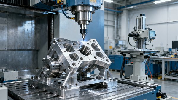
Robotic Polishing for Aerospace Parts Gets Harder on Complex Curves
Publication Date
author
As robotic polishing for aerospace parts shifts from relatively simple geometries to compound curves, the main challenge is no longer basic automation. It is process stability. On complex surfaces, small changes in tool angle, local curvature, edge transition, and material response can quickly turn into inconsistent surface finish, over-polishing, under-polishing, or rework. For engineering teams, operators, buyers, and manufacturing leaders, the practical question is straightforward: how do you keep finish quality repeatable while controlling validation cost and production risk? The short answer is that success increasingly depends on three factors working together: smart factory automation solutions, robotic arm vibration analysis, and servo motor torque curve analysis. When these are treated as measurable engineering variables rather than marketing features, robotic polishing becomes far more predictable on aerospace-grade parts.
Why complex curves make robotic polishing much harder than flat aerospace surfaces

Many aerospace components now include freeform geometries, blended radii, thin-wall sections, aerodynamic contours, and tight transition zones that are difficult to finish consistently. A robot can repeat a path well, but polishing quality depends on much more than path repetition alone. The contact condition between tool and part is constantly changing on curved surfaces.
That creates several production problems:
- Unstable contact pressure: Even if the programmed force target stays the same, effective pressure at the polishing point can vary as curvature changes.
- Tool orientation drift: Minor angular deviation can change scratch pattern, removal rate, and edge behavior.
- Surface speed inconsistency: The local relative motion between abrasive and workpiece may fluctuate across compound geometry.
- Robot structural response: Arm posture changes affect stiffness, and different reach positions can amplify vibration.
- Material sensitivity: Aerospace alloys and coated surfaces often have narrow process windows for acceptable finish.
This is why robotic polishing for aerospace parts gets harder on complex curves: geometry variation exposes every weakness in the robot, end-effector, force control logic, and motion tuning. What works on a flat panel may fail on a curved blade section, housing contour, or structural fitting.
What engineers, buyers, and decision-makers should evaluate first
Although different stakeholders ask different questions, their core concern is the same: can the process deliver stable, auditable results under real production conditions?
Engineers and process developers usually care most about:
- How to maintain uniform contact force across changing curvature
- How robot posture affects stiffness and vibration
- How to validate surface roughness, dimensional integrity, and consistency
- How much tuning is needed for each part family
Operators and cell users focus on:
- Ease of setup and recipe changeover
- Sensitivity to tool wear and abrasive replacement
- Alarm visibility and troubleshooting guidance
- Cycle stability during long production runs
Procurement teams tend to ask:
- Which technical specifications actually predict production performance
- Whether the supplier can prove capability on curved aerospace parts, not just demo samples
- Expected maintenance load, spare parts requirements, and integration cost
- How long qualification and acceptance testing will take
Business leaders and plant decision-makers usually want clarity on:
- Whether automation reduces rework and dependency on manual polishing specialists
- How scalable the solution is across multiple part programs
- Where the real return on investment comes from
- What technical risks could delay launch or customer approval
For all of these groups, the most useful evaluation method is to stop looking at robotic polishing as a generic automation purchase and start treating it as a controlled finishing process with measurable dynamic behavior.
Why force control alone is not enough on aerospace curved parts
A common mistake in robotic polishing projects is assuming that adding force control solves the complexity problem. In reality, force control is necessary but insufficient. A robot may maintain nominal force while still producing unstable finish because the true polishing outcome also depends on vibration, compliance, spindle behavior, abrasive condition, path strategy, and robot arm posture.
On complex curves, the same target force can produce different material removal rates because:
- The contact patch changes shape as the surface curves
- The tool may enter micro-sliding or micro-bouncing states
- Arm stiffness varies across the workspace
- Acceleration and deceleration near geometric transitions disturb contact quality
This is why advanced smart factory automation solutions increasingly combine force feedback with path adaptation, tool wear compensation, real-time monitoring, and post-process quality data. The best systems do not simply command a force value. They monitor whether the entire polishing condition remains inside an acceptable process window.
How robotic arm vibration analysis improves finish quality and repeatability
For complex curved aerospace parts, robotic arm vibration analysis is one of the most underused but most valuable diagnostic tools. Surface finish defects are often treated as programming errors or abrasive problems when the deeper cause is dynamic instability in the robotic system.
Vibration matters because polishing is a contact-intensive process. Unlike non-contact tasks, it continuously excites the robot structure. If the arm, tool, spindle, or fixture enters a resonance-prone condition, the effect may appear as:
- Visible chatter marks
- Non-uniform gloss or texture
- Localized over-removal at edges or curvature transitions
- Rapid abrasive wear
- Part-to-part variability despite identical programming
Robotic arm vibration analysis helps teams identify where the process becomes unstable. In practice, this means measuring vibration signatures across different robot poses, tool speeds, contact forces, and path segments. Engineers can then compare stable and unstable regions of the cycle.
Useful questions include:
- Does vibration increase when the robot reaches farther from its base?
- Are specific joint configurations linked to poorer finish quality?
- Do certain spindle speeds excite structural frequencies?
- Does fixture rigidity contribute to oscillation?
For buyers and decision-makers, this has a practical takeaway: if a supplier cannot explain how vibration is measured, interpreted, and reduced, there is a higher chance that the process is being tuned by trial and error rather than engineering evidence.
Why servo motor torque curve analysis matters in robotic polishing cells
Servo motor torque curve analysis provides another critical layer of insight, especially when polishing paths involve frequent orientation changes, varying curvature, and non-uniform contact conditions. Torque behavior tells you how hard the robot axes are working to maintain motion and position while under process load.
On complex aerospace parts, abnormal or inconsistent torque patterns may indicate:
- Excessive process load in specific path regions
- Poor trajectory smoothing
- Mechanical resistance or backlash issues
- Unfavorable robot posture with reduced rigidity
- Compensation settings that are too aggressive or too weak
Torque curve analysis is especially valuable because it connects motion control performance to actual polishing results. If one segment consistently shows higher torque spikes and that same segment also produces finish variation, the root cause becomes easier to isolate.
For engineering teams, torque data can support:
- Optimization of path planning and acceleration profiles
- Selection of better tool approach angles
- Adjustment of contact force envelopes
- Early detection of maintenance issues before quality drifts
For procurement teams, servo motor torque curve analysis is also a strong vendor assessment criterion. It shows whether the supplier understands process dynamics at a technical level, not just at a demonstration level.
What a robust smart factory automation solution should include
If the goal is reliable robotic polishing for aerospace parts, especially on complex curves, the automation solution should be judged as a complete system. A capable setup typically includes the following elements:
- Offline and adaptive path planning: Ability to generate and refine polishing paths for freeform geometry.
- Force and compliance management: Stable control of contact conditions across changing surfaces.
- Integrated sensing: Monitoring of force, vibration, spindle load, torque, and optionally surface inspection data.
- Recipe management: Repeatable process parameters for different part families and finish requirements.
- Tool wear compensation: Mechanisms to account for abrasive degradation during production.
- Traceable validation workflow: Data collection that supports aerospace quality requirements and internal process approval.
- Operator usability: Clear interfaces, guided recovery procedures, and manageable changeover steps.
In smart factory environments, the real value is not only automation of labor. It is automation of process knowledge. The stronger the data loop between the robot, the polishing tool, and quality verification, the more scalable the process becomes.
How to reduce validation cost and qualification risk
Validation costs rise quickly when robotic polishing is applied to complex curves because every unstable variable creates more test cycles, more sample parts, and more uncertainty. A better strategy is to structure qualification around measurable risk points instead of broad trial campaigns.
A practical validation plan often includes:
- Segment the geometry by difficulty: Separate flat, convex, concave, edge-transition, and tight-radius regions.
- Map robot posture and dynamic behavior: Identify weak stiffness zones and vibration-sensitive positions.
- Correlate process signals with finish outcomes: Link vibration, force, and torque trends to roughness and visual results.
- Set acceptance windows: Define allowable variation ranges for key process indicators, not only final finish values.
- Test tool life early: Many polishing cells pass short demos but drift during longer production runs.
This approach helps both technical and commercial teams. Engineers gain faster root-cause visibility, while managers reduce the risk of investing in a system that performs well only under controlled demo conditions.
Questions buyers should ask suppliers before selecting a robotic polishing system
To avoid vague claims, buyers should request evidence tied to process capability on complex aerospace geometries. Useful questions include:
- What surface finish range has been achieved on comparable aerospace materials and curved features?
- How is contact force controlled and verified across freeform surfaces?
- What robotic arm vibration analysis methods are used during commissioning?
- Can the supplier provide servo motor torque curve analysis for representative polishing cycles?
- How is tool wear monitored and compensated?
- What is the expected validation timeline for a new part family?
- How much process retuning is usually required after geometry changes?
- What in-line or post-process inspection data can be integrated into the cell?
These questions move the conversation away from generic automation promises and toward actual engineering capability.
Where robotic polishing delivers the most value despite the complexity
Even though complex curves make robotic polishing more difficult, automation still delivers strong value in the right scenarios. Aerospace manufacturers usually benefit most when they face one or more of the following conditions:
- Manual polishing quality varies significantly by operator
- Labor availability for skilled finishing work is limited
- Parts require repeatable cosmetic and functional surface consistency
- Production volumes justify process standardization
- Traceability requirements are increasing
- Rework and validation delays are hurting throughput
In these cases, the goal is not perfect automation from day one. The goal is controlled repeatability, data-backed optimization, and gradual expansion from simpler zones to more demanding geometries.
Conclusion: the winning approach is data-driven, not demo-driven
Robotic polishing for aerospace parts gets harder on complex curves because geometry variation exposes every weakness in force stability, motion control, structural stiffness, and process validation. That is why successful implementation depends on more than a robot and a polishing head. It requires a measurable, data-driven finishing strategy.
For technical teams, robotic arm vibration analysis and servo motor torque curve analysis offer direct insight into why finish quality changes across difficult surfaces. For procurement and management teams, these same data points help separate real engineering capability from polished sales presentations. And for operations, smart factory automation solutions create the foundation for repeatability, traceability, and lower long-term rework cost.
The clearest judgment is this: on complex aerospace curves, the best robotic polishing systems are not the ones that look most impressive in a demo. They are the ones that can explain, measure, and control process behavior with engineering evidence.
Search News
Hot Articles
- Carbon Fiber StructuresHow to Specify Aerospace Carbon Fiber Assemblies for Lightweight, Load-Bearing PartsJul 11, 2026
- Machine VisionXiaomi, Alibaba DAMO Academy Drive Open-Source Robotics Model Ecosystem, Lowering Algorithm Development Barriers for Overseas SMEs Adopting Chinese Robotics SolutionsMar 30, 2026
- Cobots & ArmsShanxi 'AI+' Conference Showcases Embodied Intelligence with Multinational Buyer Engagement: Key Industry ImplicationsMar 30, 2026
Popular Tags
Recommended News
 Jul 11, 2026How to Specify Aerospace Carbon Fiber Assemblies for Lightweight, Load-Bearing PartsAerospace carbon fiber assemblies: learn how to specify laminate design, load data, joining methods, and inspection controls for lighter, reliable load-bearing aerospace parts.Elena Rostova (UAV Systems Researcher)
 Mar 30, 2026Xiaomi, Alibaba DAMO Academy Drive Open-Source Robotics Model Ecosystem, Lowering Algorithm Development Barriers for Overseas SMEs Adopting Chinese Robotics SolutionsXiaomi & Alibaba DAMO Academy's open-source robotics models lower algorithm barriers for global SMEs. Boost efficiency in manufacturing, logistics & smart retail with ROS 2 compatible solutions.TSV Data Lab
 Mar 30, 2026Shanxi 'AI+' Conference Showcases Embodied Intelligence with Multinational Buyer Engagement: Key Industry ImplicationsShanxi 'AI+' Conference highlights embodied intelligence with Tesla, Ubtech & Jiantao showcasing multimodal robotics. 40+ global buyers validated tech on-site, creating new B2B channels for industrial automation & AI solutions.Chen Wei (Automation Lead Engineer)
 Mar 30, 2026Zhongguancun Unveils 6G Integrated Sensing-Computing-Intelligence Platform to Empower Embodied Robots for Global Industrial ApplicationsZhongguancun's new 6G platform revolutionizes industrial robotics with <10ms latency, empowering global automotive, logistics & port automation. Discover how this tech boosts China's smart manufacturing exports.TSV Data Lab
 Mar 30, 2026Mech-Mind Tianjin Embodied Intelligence R&D and Production Base Goes Live, Cutting Delivery Time by 20%–30% for Global Customized AMR+Vision SolutionsMech-Mind's Tianjin AMR+Vision production base cuts delivery time by 20%-30% for欧美 & Latin American markets. Discover how this PLd-certified facility accelerates customized robotics solutions for smart manufacturing and logistics.Chen Wei (Automation Lead Engineer)
 Mar 30, 2026Boao Forum Reveals 'Co-evolution of Big and Small Brains' Trend in Humanoid Robots, China's Embodied Intelligence Accelerates Adaptation to Overseas Manufacturing Service ScenariosDiscover how China's humanoid robots, featuring 'Co-evolution of Big and Small Brains,' are revolutionizing global manufacturing. Learn about Embodied Tian Gong 3.0's ISO compliance and overseas deployment at Boao Forum 2026.Chen Wei (Automation Lead Engineer)
 Mar 30, 2026China Railway Industrial Secures Patent for Embodied Robotics in Material Handling, Boosting High-Precision Delivery Capabilities for Overseas Infrastructure and Manufacturing ProjectsChina Railway Industrial's new patent for embodied robotics in material handling boosts high-precision delivery for global infrastructure & manufacturing. Discover how this innovation enhances logistics accuracy in automotive, rail transit & EPC projects.Chen Wei (Automation Lead Engineer)
 Oct 16, 2026Choosing a Rugged Edge AI Box Supplier: Thermal Tests and Lifecycle SupportChoose a rugged edge AI box supplier with proven thermal performance and reliable lifecycle support. Discover the tests and commitments to verify before you buy.TSV Data Lab
 Oct 15, 2026R&D Cost Reduction Services: How to Evaluate Fees, Savings, and ROIEvaluate R&D cost reduction services with confidence. Compare fees, verify savings, and calculate ROI without compromising performance. Discover how to choose a provider that delivers real value.Chen Wei (Automation Lead Engineer)
 Oct 15, 2026How Should You Compare TechStat Vanguard 5-Axis CNC Tolerances?TechStat Vanguard 5-axis CNC tolerance comparison: learn how to verify part accuracy, assess inspection evidence, and choose suppliers that reliably meet your drawing requirements.Dr. Marcus Vance
 Oct 14, 2026Drone Frame Composites: Carbon Fiber vs. Fiberglass for Weight and StiffnessExplore drone structural materials composites: compare carbon fiber and fiberglass for weight, stiffness, cost, and antenna compatibility. Find the right material for your drone frame.Elena Rostova (UAV Systems Researcher)
 Oct 13, 2026Smart Cameras vs. PC-Based Machine Vision: Which Fits High-Speed Inspection?This industrial product comparison for machine vision weighs smart cameras vs. PC-based systems on latency, throughput, and cost. Discover your best fit for high-speed inspection.TSV Data Lab
 Oct 12, 2026How to Verify RoHS Compliance in Industrial Sensing Systems Before DeploymentRoHS compliant sensing systems: learn how to verify materials, supplier declarations, testing, and configuration controls before industrial deployment.TSV Data Lab
 Oct 11, 2026How Procurement-Oriented Content Taxonomy Improves B2B Buying JourneysProcurement-oriented content taxonomy streamlines B2B buying journeys with clearer evidence, supplier comparisons, risk visibility, and faster approvals.TSV Data Lab
 Oct 10, 2026How to Select a Machine Performance Monitoring Platform for OEE and Downtime ReductionMachine performance monitoring platform selection guide: validate machine states, OEE data, downtime reasons, integrations, and scalability to reduce losses with confidence.TSV Data Lab
 Oct 08, 2026How to Machine Inconel 625 Blades Without Heat Cracks or Edge ChippingInconel 625 blade machining guide: prevent heat cracks, edge chipping, chatter, and work hardening with proven tooling, cooling, fixturing, and inspection strategies.Dr. Marcus Vance
 Oct 07, 2026How to Evaluate an HMI Panel Distributor for Industrial Automation ProjectsHMI panel distributor evaluation guide: verify technical compatibility, traceability, supply reliability, lifecycle support, and total cost for automation projects.Victor Lin (Chief Software Architect)
 Oct 06, 2026Navigation Fault Tolerance Standards for AMRs: What Safety Teams Must VerifyNavigation fault tolerance standards: learn what AMR safety teams must verify, from localization loss and sensor faults to stopping distance, safe restart, and site-specific validation.Chen Wei (Automation Lead Engineer)
 Oct 05, 2026Calculating Edge Computing Total Cost of Ownership Across Distributed SitesEdge computing ownership cost explained: calculate deployment, energy, connectivity, security, remote support, and refresh costs across distributed sites.TSV Data Lab
 Oct 04, 2026CAD/CAM Benchmarking in the GCC: What Manufacturers Should Ask a ConsultantCAD CAM benchmark consultant GCC guide: learn the key questions manufacturers should ask to validate post-processors, workflows, machine performance, and production risk.Victor Lin (Chief Software Architect)
 Oct 03, 2026Selecting Automotive Radar Sensor Modules for ADAS Range, Resolution, and IntegrationAutomotive radar sensor module selection guide for ADAS: compare range, resolution, field of view, latency, and integration to build safer, reliable vehicle systems.TSV Data Lab
 Oct 02, 2026How to Qualify Machined Parts Suppliers for Hard Tech ProgramsHard tech supply chain machined parts demand rigorous supplier qualification. Learn how to assess capability, traceability, quality controls, and delivery resilience.Dr. Marcus Vance
 Oct 01, 2026How to Select an Outdoor Security Radar Sensor for Perimeter Detection?Outdoor security radar sensor selection guide: compare range, accuracy, false-alarm control, integration, and field testing for reliable perimeter detection.TSV Data Lab
 Sep 30, 2026How to Evaluate Solid-State LiDAR Hardware for Outdoor Autonomous VehiclesSolid state LiDAR hardware evaluation guide for outdoor autonomous vehicles—compare range, point-cloud quality, environmental resilience, integration, and safety.TSV Data Lab