Robot Thermal Testing Explained: What to Measure for Motors, Joints, and Duty Cycles
Publication Date
author
Robot Thermal Testing Explained: What to Measure for Motors, Joints, and Duty Cycles
Robot thermal testing is essential when performance claims must be verified with measurable engineering evidence.
In robotics, heat is not a side issue. It is often the earliest signal of overload, friction, weak cooling, or poor duty-cycle matching.
A robot may meet speed targets in short demos, yet fail thermal limits during real production schedules.
That is why robot thermal testing matters for motors, joints, reducers, drives, and cable routing as a complete thermal system.
This article breaks down what to measure, how to run the test, and how to judge results without relying on marketing language.
Why robot thermal testing reveals real reliability
Many robot failures begin as temperature drift, not immediate shutdown.
Motor windings age faster under sustained heat. Grease degrades. Encoder accuracy shifts. Drive electronics may derate output before alarms appear.
In practical evaluations, robot thermal testing helps answer three hard questions.
- Can the robot sustain the claimed payload and cycle rate?
- Which joint becomes the thermal bottleneck first?
- How much safety margin remains in the intended environment?
These questions are especially important in welding, palletizing, dispensing, inspection, and autonomous handling tasks.
They also matter in compact cells, where airflow is poor and surrounding equipment adds radiant heat.
Start with the right thermal metrics
Good robot thermal testing is not just about recording the hottest surface spot.
You need a structured set of measurements that connects temperature to load, motion, and time.
Motor-related measurements
- Winding temperature or estimated winding temperature from the servo model.
- Motor housing temperature at fixed points.
- Current draw during peak acceleration and steady motion.
- Torque utilization over the full cycle.
- Thermal rise above ambient, not only absolute temperature.
Winding temperature is usually the critical life factor, even when the housing still looks acceptable.
Joint and gearbox measurements
- Outer joint casing temperature.
- Reducer temperature near the bearing zone.
- Backlash change before and after thermal soak.
- Friction rise inferred from current at matched trajectories.
- Temperature imbalance between adjacent joints.
A rising joint temperature with stable payload can indicate lubrication loss or alignment issues.
Drive and cabinet measurements
- Drive heat sink temperature.
- Cabinet inlet and outlet air temperature.
- Fan operation, airflow blockage, and filter condition.
- Internal derating events or thermal warnings.
Sometimes the robot arm passes, but the control cabinet becomes the real thermal limit.
How to define test conditions that actually matter
Robot thermal testing only becomes useful when the duty profile reflects real operation.
A short no-load cycle will almost always understate thermal stress.
Set the test around the application, not the brochure.
Define the thermal boundary conditions
- Ambient temperature and humidity.
- Enclosure or open-cell configuration.
- Nearby heat sources such as welders, ovens, or power cabinets.
- Airflow speed around joints and motors.
- Mounting orientation, especially ceiling or wall mounting.
Mounting orientation matters because gravity changes load distribution across robot joints.
Define the motion profile
- Payload mass and tool center point offset.
- Path shape, acceleration, speed, and dwell time.
- Cycle duration and cycles per hour.
- Percentage of time spent near maximum torque.
- Worst-case posture for each major joint.
The worst thermal case is often a posture with high static torque, not the fastest move.
Run long enough to reach thermal equilibrium
A meaningful robot thermal testing program includes warm-up, steady operation, and cooldown observation.
Do not stop after ten minutes if temperatures are still climbing.
For many industrial robots, one to three hours is more realistic for a representative thermal plateau.
What to measure on motors, joints, and duty cycles
This is where robot thermal testing becomes actionable.
Use a consistent checklist so data can be compared across platforms, suppliers, and applications.
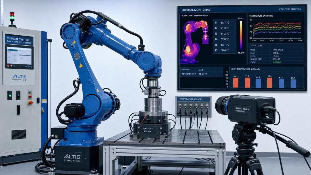
If possible, combine thermocouples, internal controller logs, and infrared validation.
Each method covers a different part of the thermal picture.
How to interpret robot thermal testing results
Raw temperature values alone do not tell the full story.
The more useful approach is to read trend shape, rate of rise, and thermal recovery.
Look for these patterns
- Fast early rise, then plateau. Usually acceptable if below the design threshold.
- Slow continuous rise. This suggests the robot has not reached thermal balance.
- One joint rising much faster than others. This points to localized stress.
- High temperature after low-speed holding. This can indicate static torque overload.
- Long cooldown time. This may show limited heat dissipation capacity.
In supplier comparison, identical ambient conditions are critical.
Even a small ambient change can distort a thermal benchmark.
Judge margin, not just pass or fail
A robot that barely passes a lab test may still be risky in deployment.
Real factories add dust, filter clogging, hotter summers, and cycle drift over time.
For that reason, robot thermal testing should estimate operating margin against expected field variation.
Common mistakes that weaken thermal evaluation
Several shortcuts make robot thermal testing look complete while hiding the real risk.
- Testing without payload offset, even though the tool has a long moment arm.
- Using average current only, while ignoring repeated acceleration peaks.
- Measuring one joint surface and assuming all robot joints behave similarly.
- Ignoring cabinet temperature because the arm itself remains within limit.
- Stopping the test before thermal stabilization.
- Skipping repeat tests after changing grease, gearbox preload, or software tuning.
These mistakes are common during rushed acceptance reviews.
They also explain why field overheating sometimes appears after a seemingly successful factory test.
A practical robot thermal testing checklist
For a clean and repeatable evaluation, use this workflow.
- Document ambient conditions, mounting orientation, and enclosure status.
- Define payload mass, center of gravity, and tool center point offset.
- Program the real motion cycle, including dwell and holding periods.
- Log motor current, torque, temperature, and controller warnings.
- Measure key robot joints with fixed sensor positions.
- Run until thermal plateau or a clearly established rise trend.
- Check accuracy, backlash, and recovery after cooldown.
- Compare results against the intended duty cycle, not a generic rating.
This process keeps robot thermal testing linked to procurement decisions, reliability planning, and supplier qualification.
Final takeaway
Robot thermal testing is one of the clearest ways to separate lab-ready claims from production-ready performance.
When you measure motor heating, robot joints, reducer behavior, and true duty-cycle stress together, hidden limits become visible early.
That reduces qualification risk, avoids undersized selections, and improves long-term uptime.
In real engineering work, the best robot thermal testing program is not the most complicated one.
It is the one that matches actual load, captures the hottest bottleneck, and shows whether enough thermal margin remains for the field.
Search News
Hot Articles
- Carbon Fiber StructuresHow to Specify Aerospace Carbon Fiber Assemblies for Lightweight, Load-Bearing PartsJul 11, 2026
- Machine VisionXiaomi, Alibaba DAMO Academy Drive Open-Source Robotics Model Ecosystem, Lowering Algorithm Development Barriers for Overseas SMEs Adopting Chinese Robotics SolutionsMar 30, 2026
- Cobots & ArmsShanxi 'AI+' Conference Showcases Embodied Intelligence with Multinational Buyer Engagement: Key Industry ImplicationsMar 30, 2026
Popular Tags
Recommended News
 Jul 11, 2026How to Specify Aerospace Carbon Fiber Assemblies for Lightweight, Load-Bearing PartsAerospace carbon fiber assemblies: learn how to specify laminate design, load data, joining methods, and inspection controls for lighter, reliable load-bearing aerospace parts.Elena Rostova (UAV Systems Researcher)
 Mar 30, 2026Xiaomi, Alibaba DAMO Academy Drive Open-Source Robotics Model Ecosystem, Lowering Algorithm Development Barriers for Overseas SMEs Adopting Chinese Robotics SolutionsXiaomi & Alibaba DAMO Academy's open-source robotics models lower algorithm barriers for global SMEs. Boost efficiency in manufacturing, logistics & smart retail with ROS 2 compatible solutions.TSV Data Lab
 Mar 30, 2026Shanxi 'AI+' Conference Showcases Embodied Intelligence with Multinational Buyer Engagement: Key Industry ImplicationsShanxi 'AI+' Conference highlights embodied intelligence with Tesla, Ubtech & Jiantao showcasing multimodal robotics. 40+ global buyers validated tech on-site, creating new B2B channels for industrial automation & AI solutions.Chen Wei (Automation Lead Engineer)
 Mar 30, 2026Zhongguancun Unveils 6G Integrated Sensing-Computing-Intelligence Platform to Empower Embodied Robots for Global Industrial ApplicationsZhongguancun's new 6G platform revolutionizes industrial robotics with <10ms latency, empowering global automotive, logistics & port automation. Discover how this tech boosts China's smart manufacturing exports.TSV Data Lab
 Mar 30, 2026Mech-Mind Tianjin Embodied Intelligence R&D and Production Base Goes Live, Cutting Delivery Time by 20%–30% for Global Customized AMR+Vision SolutionsMech-Mind's Tianjin AMR+Vision production base cuts delivery time by 20%-30% for欧美 & Latin American markets. Discover how this PLd-certified facility accelerates customized robotics solutions for smart manufacturing and logistics.Chen Wei (Automation Lead Engineer)
 Mar 30, 2026Boao Forum Reveals 'Co-evolution of Big and Small Brains' Trend in Humanoid Robots, China's Embodied Intelligence Accelerates Adaptation to Overseas Manufacturing Service ScenariosDiscover how China's humanoid robots, featuring 'Co-evolution of Big and Small Brains,' are revolutionizing global manufacturing. Learn about Embodied Tian Gong 3.0's ISO compliance and overseas deployment at Boao Forum 2026.Chen Wei (Automation Lead Engineer)
 Mar 30, 2026China Railway Industrial Secures Patent for Embodied Robotics in Material Handling, Boosting High-Precision Delivery Capabilities for Overseas Infrastructure and Manufacturing ProjectsChina Railway Industrial's new patent for embodied robotics in material handling boosts high-precision delivery for global infrastructure & manufacturing. Discover how this innovation enhances logistics accuracy in automotive, rail transit & EPC projects.Chen Wei (Automation Lead Engineer)
 Sep 23, 2026How to Evaluate a Machine Vision System Integrator for High-Speed Inspection LinesChoose a machine vision system integrator with proven expertise in high-speed inspection, reliable reject timing, robust optics, and measurable acceptance criteria.TSV Data Lab
 Sep 23, 2026What drives ultra-precision machining cost at 1-micron tolerance?Ultra precision machining cost per part at 1 micron tolerance depends on process, material, metrology, and yield. Learn how to compare quotes confidently.Dr. Marcus Vance
 Sep 22, 2026Drone Engine-T550CC Applications: Build the UAV Power System Around the MissionAn application guide for Drone Engine-T550CC integration, covering payload planning, airframe matching, cooling, fuel, vibration, test procedures, documentation, and service preparation.Elena Rostova (UAV Systems Researcher)
 Sep 22, 2026How to Evaluate Industrial Edge Computing Vendors for Factory DeploymentIndustrial edge computing vendor evaluation guide for factories: compare latency, protocol fit, reliability, security, and lifecycle support before deployment.TSV Data Lab
 Sep 21, 2026Drone Payload Integration: Matching Power, Data, and Center of Gravity for Reliable FlightsDrone payload integration made practical: balance power, data, center of gravity, and endurance to build safer, more reliable mission-ready flights.Elena Rostova (UAV Systems Researcher)
 Sep 20, 2026Autonomous Navigation Pricing: Cost Drivers and Budget Benchmarks for AMR ProjectsAutonomous navigation price explained: compare AMR cost drivers, software, sensors, integration, safety, and lifecycle budgets to build a scalable project plan.Chen Wei (Automation Lead Engineer)
 Sep 19, 2026How to Scope Automation Integration Services for Multi-System Factory ProjectsAutomation integration services: learn how to scope multi-system factory projects with clear workflows, interface contracts, safety boundaries, and acceptance criteria.Victor Lin (Chief Software Architect)
 Sep 18, 2026Selecting UAV Aerospace Structural Parts for Strength, Weight, and Fatigue LifeUAV aerospace structural parts guide: compare strength, weight, stiffness, fatigue life, joints, and traceability to select reliable flight-ready components.Elena Rostova (UAV Systems Researcher)
 Sep 17, 2026Selecting Commercial Drone Payloads for European Inspection ProjectsCommercial drone payloads Europe: learn how to select RGB, thermal and LiDAR systems for compliant, reliable inspection data and better project outcomes.Elena Rostova (UAV Systems Researcher)
 Sep 16, 2026Machining Tolerance Validation: How to Verify Critical Dimensions Before Production ReleaseMachining tolerance analysis validation: verify critical dimensions, measurement systems, process capability, and tolerance stacks before production release.Dr. Marcus Vance
 Sep 15, 2026AGV Tape Guidance vs Laser Navigation: Which Fits Your Warehouse Layout?AGV tape guidance comparison: discover how tape and laser navigation fit changing warehouse layouts, docking needs, floor conditions, maintenance, and route flexibility.Chen Wei (Automation Lead Engineer)
 Sep 14, 2026How Point Cloud Analytics Improves Asset Inspection Workflows Across GCC ProjectsPoint cloud analytics GCC helps project leaders improve asset inspections with accurate change detection, safer workflows, and faster maintenance decisions.TSV Data Lab
 Sep 13, 2026How Aerospace Manufacturers Can Build a Digital Thread From Design to Certified ProductionDigital manufacturing for aerospace: learn how to build a traceable digital thread from design through certified production, supplier control, and audit-ready compliance.Victor Lin (Chief Software Architect)
 Sep 12, 2026How to Select a Thermal Sensor for Mapping Drones in Surveying ProjectsMapping drone thermal sensor selection made simple: compare GSD, radiometric data, NETD, calibration, and workflow fit for accurate, survey-ready thermal maps.Elena Rostova (UAV Systems Researcher)
 Sep 11, 2026Integrating Photogrammetry Workflows into Digital Twin Projects Without Data BottlenecksPhotogrammetry workflow integration for digital twins: learn how to streamline capture, validation, versioning, and delivery to prevent data bottlenecks.Victor Lin (Chief Software Architect)
 Sep 10, 2026Hard-Tech Supply Chain Procurement: Qualifying Suppliers to Cut Lead-Time RiskHard-tech supply chain procurement guide: qualify suppliers with proven process, traceability, capacity, and change control to reduce lead-time risk.Chen Wei (Automation Lead Engineer)
 Sep 09, 2026Industrial Application Notes: Cost Factors That Shape Automation Project BudgetsIndustrial application notes cost factors explained: uncover the engineering, safety, integration, and commissioning variables that shape accurate automation budgets.Victor Lin (Chief Software Architect)