3D Printing for Aerospace Prototypes Where Speed Stops Being the Main Gain
Publication Date
author
In aerospace development, 3d printing for aerospace prototypes is no longer valued only for speed. Engineers and buyers now measure how additive processes affect qualification risk, material behavior, and downstream manufacturability—especially in applications like 3d metal printing for rocket nozzles, 5 axis cnc for aerospace impellers, and precision grinding for aerospace bearings. This article examines where rapid iteration ends and engineering truth begins.
Why speed alone no longer defines prototype value in aerospace
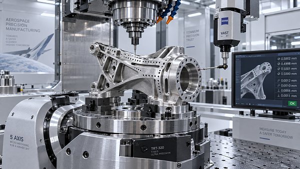
For early concept validation, rapid turnaround still matters. A bracket, duct, housing, or fixture produced in 2–5 days can compress design loops and reveal packaging errors quickly. Yet once a prototype is used for airflow testing, thermal evaluation, vibration review, assembly rehearsal, or customer sign-off, the key question changes. The team is no longer asking only how fast a part can be made. It is asking whether the process creates reliable engineering evidence.
That shift is especially visible in 3d printing for aerospace prototypes because many printed parts sit between concept and certification. They may not be final flight hardware, but they influence geometry freezes, tooling decisions, supplier selection, and budget planning. A prototype that hides shrinkage behavior, anisotropy, porosity, or surface limitations can save 1 week in development and cost 3–6 months later in redesign, re-qualification, or process transfer.
For procurement teams, the issue is just as practical. Quotes for additive parts are often compared by lead time and unit price, while the real cost drivers sit elsewhere: powder traceability, build orientation strategy, support removal risk, heat-treatment route, non-destructive inspection scope, and machining allowance. In aerospace sourcing, vague claims such as “high precision” are not enough. Buyers need tolerance windows, post-processing steps, and inspection boundaries stated in the RFQ.
TechStat Vanguard approaches this topic from a benchmarking perspective. The goal is not to praise additive manufacturing as a universal answer. The goal is to clarify when additive shortens learning cycles, when hybrid routes work better, and when conventional machining still delivers lower risk. In hard-tech procurement, parameters matter more than slogans, and prototype decisions should reduce uncertainty instead of relocating it.
What changes after the first fast iteration?
The first printed part often proves fit and form. The second and third iterations should prove process stability. By that stage, aerospace teams usually review at least 4 dimensions: dimensional repeatability across builds, material consistency between batches, compatibility with downstream machining, and relevance to final production intent. If those 4 points are not defined, prototype speed becomes a misleading KPI.
- Design teams need to know whether a thin wall, lattice, internal channel, or overhang is printable without unrealistic support strategies.
- Operators need practical work instructions on powder handling, orientation, heat treatment, and finishing, not only CAD freedom.
- Buyers need comparable quotes that separate print cost, machining cost, inspection cost, and scrap risk.
- Decision-makers need evidence that the prototype route supports the long-term industrialization path within 2–3 sourcing stages.
Which aerospace prototype scenarios really benefit from additive manufacturing?
Not every aerospace part benefits from additive manufacturing in the same way. The strongest use cases usually combine one or more of these factors: geometry complexity, low initial volume, internal features that are hard to machine, urgent iteration cycles, or the need to consolidate multiple parts into 1 assembly. In these cases, 3d printing for aerospace prototypes can improve development efficiency without forcing an unrealistic production roadmap.
Rocket nozzles are a clear example. With 3d metal printing for rocket nozzles, internal cooling paths and compact thermal management features can be evaluated earlier than with traditional segmented fabrication. However, nozzle prototypes must be reviewed for wall thickness control, powder evacuation, hot-section finishing, and the extent of post-build machining. A fast print is useful only if thermal and structural test data remain meaningful after those finishing steps.
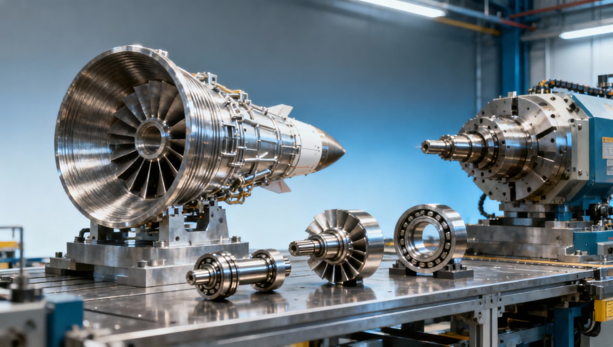
Impellers and aerodynamic rotating components illustrate a different boundary. Some prototype geometries can be explored via additive methods, especially in the concept phase, but 5 axis cnc for aerospace impellers often remains critical when the project moves toward high-surface-finish, tight-balance, and precise blade profile validation. Here, additive may support near-net-shape learning, while machining confirms the geometry that matters for high-speed performance.
Bearing-related components create another lesson. Precision grinding for aerospace bearings exists because final function often depends on surface integrity, roundness, waviness, and tight dimensional control. Additive can still contribute to surrounding tooling, housings, development fixtures, and some non-final test hardware, but not every bearing-critical feature should be validated on an as-printed basis. The prototype strategy must follow function, not manufacturing fashion.
Scenario-based selection logic
The table below helps engineering and sourcing teams compare where additive manufacturing creates real prototype value and where hybrid or conventional routes may be more reliable.
Aerospace teams often get better results when they define prototype purpose in 3 levels: visual and assembly validation, functional bench testing, and production-intent process proving. Once that 3-level structure is clear, supplier discussions become more objective, and additive manufacturing can be assigned to the right stage instead of being overextended.
What technical metrics should engineers and buyers verify before ordering?
A robust RFQ for 3d printing for aerospace prototypes should describe more than material name and CAD file. At minimum, teams should define the intended application, expected operating environment, target dimensions, critical surfaces, post-processing needs, and inspection scope. For metal parts, many sourcing failures happen because the printed geometry is quoted first, while support strategy, machining stock, and heat treatment are addressed too late.
Tolerance expectations should also be realistic. Complex additive parts often require different tolerancing logic for freeform surfaces, holes, interfaces, and machined datums. A practical engineering approach is to separate the part into 3 zones: as-printed non-critical features, machined functional features, and reference features used for inspection. This can shorten supplier clarification cycles by 20–30% in typical B2B projects because fewer assumptions are left open.
Material behavior must be treated carefully. Aerospace prototypes may need to reflect strength, thermal response, or fatigue trends close to production intent, but not every additive process gives the same result in every build orientation. Teams should ask whether the quoted route includes stress relief, HIP where appropriate, finish machining, surface treatment, or non-destructive examination. If not, test conclusions may be directionally useful but not qualification-relevant.
For cross-functional teams, the most effective review usually happens through a 5-point checklist: geometry feasibility, material route, tolerancing plan, inspection method, and industrialization path. That checklist helps prevent a common problem in aerospace procurement—buying a prototype that answers a design question but creates a manufacturing question that is harder and costlier to solve.
Core evaluation dimensions for aerospace prototype sourcing
The following matrix is useful when comparing additive suppliers, hybrid shops, or conventional machining partners for aerospace prototype programs.
This table also highlights why TSV emphasizes engineering benchmarking. A quote without process boundaries is not a reliable decision tool. In aerospace, a slightly longer review cycle of 3–7 days can be preferable if it prevents multiple weeks of non-conforming rework, supplier dispute, or invalid test data.
A practical RFQ checklist
- State whether the part is for fit check, thermal test, vibration test, fluid testing, or production-intent evaluation.
- Mark critical features on the drawing and separate them from cosmetic or non-critical regions.
- Specify required post-processing within the quote scope, including machining, polishing, stress relief, coating, or grinding.
- Request an expected lead-time split, such as build preparation, printing, heat treatment, machining, and inspection over 1–3 stages.
- Ask for deviation disclosure if the supplier adjusts orientation, support design, or machining allowance from the original model.
How do additive, 5 axis CNC, and precision grinding compare in prototype programs?
Aerospace prototype planning works best when teams stop treating manufacturing routes as competitors in a single race. In reality, additive manufacturing, 5 axis cnc for aerospace impellers, and precision grinding for aerospace bearings solve different engineering problems. Additive is strong where geometry freedom and low-volume iteration matter. Multi-axis CNC is strong where precise surfaces, controlled datums, and repeatable aerodynamic or structural geometry are required. Grinding is indispensable when surface integrity and tight rotational accuracy dominate performance.
This means the smartest prototype strategy is often hybrid. A team may print a near-net-shape component to study packaging, thermal routing, or internal flow, then machine critical interfaces to align the prototype with test needs. In another case, a printed fixture may accelerate development while the function-critical rotating part is machined from wrought stock. The question is not which technology is modern. The question is which process produces the most decision-ready evidence.
Lead time should also be interpreted carefully. A printed metal part may appear faster at quotation stage, but if powder qualification, post-build heat treatment, support removal, machining, and inspection add another 1–2 weeks, the time advantage can narrow. Conversely, complex subtractive machining may need longer programming at the start but produce cleaner dimensional predictability once the path is proven.
For buyers, this comparison affects supplier architecture. Some projects need a single partner with additive and machining capability. Others need a benchmark-driven sourcing model where separate specialists are assessed against common acceptance criteria. TSV’s methodology is useful here because it frames manufacturing choice around tolerance chains, test purpose, and risk transfer rather than broad process branding.
Comparison by engineering objective
- Use additive first when the prototype contains internal channels, part consolidation opportunities, or design uncertainty across 2–4 likely iterations.
- Use 5 axis CNC first when blade profile accuracy, smooth surface transition, and tight datum control drive the test outcome.
- Use precision grinding where rolling contact, roundness, low waviness, or highly controlled surface finish defines the engineering value of the prototype.
- Use a hybrid route when the core geometry benefits from additive, but sealing faces, bearing seats, flanges, or balancing features require high-accuracy machining.
In practical sourcing, these distinctions often determine whether the first article becomes a learning tool or a dead end. The more function-critical the prototype, the more important it is to define process boundaries before PO release.
What procurement and compliance questions are often missed?
Aerospace buyers are under pressure from schedule, budget, and documentation requirements at the same time. That is why procurement errors often happen not in the technical concept, but in the handoff between engineering intent and supplier execution. If the RFQ does not define acceptance logic, the supplier may optimize for speed while the customer expects production-like evidence. This mismatch is common in early-stage 3d printing for aerospace prototypes.
Documentation level is one major issue. Even for non-flight prototypes, teams may still need material certificates, batch traceability, dimensional inspection, process records, or deviation reports. In organizations working toward AS9100-aligned processes, the depth of documentation should match prototype purpose. A simple assembly model does not require the same control plan as a hot-section test article, but both should have clearly defined records before manufacturing starts.
Another missed area is the transition from prototype to production sourcing. A supplier may print a successful prototype but lack the machining, NDT, or documentation discipline needed for later phases. This is not necessarily a supplier weakness; it is a qualification-scope issue. Buyers should separate 3 questions: Can the supplier make the part? Can the supplier document the part? Can the supplier support the next 2 phases of the program?
TSV’s data-driven perspective is useful because it helps procurement teams turn vague claims into measurable sourcing checkpoints. In aerospace, reducing supplier qualification cycles often depends less on marketing presentation and more on whether the quote package answers 6 operational questions before the order is placed.
Six questions buyers should ask before PO release
- What exact manufacturing route is included from raw material to final inspection?
- Which features are expected to meet tolerance in the as-printed state, and which require finish machining?
- What inspection records will be supplied at shipment, and in what format?
- What is the realistic lead time by stage, such as 3–5 days for build setup, 2–4 days for printing, and additional time for finishing and QA?
- What technical deviations may occur due to support removal, distortion control, or minimum feature limitations?
- Can the same supplier or partner network support follow-on machining, testing fixtures, or production-intent iteration?
FAQ for researchers, operators, and procurement teams
How should we choose between 3D printing and machining for an aerospace prototype?
Start with the engineering purpose. If the part is mainly for geometry confirmation, low-volume design iteration, or internal channel evaluation, additive is often the better first step. If the test depends on surface finish, tight datums, balanced rotation, or near-production dimensional accuracy, machining may be the stronger primary route. For many programs, the best answer is a hybrid path over 2 stages rather than a single-process decision.
Is 3d metal printing for rocket nozzles suitable for all development phases?
It is highly useful in early and mid-stage development where internal cooling geometry, compact design, and iteration speed matter. It is not automatically sufficient for every later-stage validation objective. Teams should check whether the printed nozzle, after heat treatment and finishing, still represents the thermal and structural conditions they need to study. That evaluation usually requires at least 3 checks: geometry, post-processing impact, and test relevance.
What lead time should buyers expect for aerospace prototype sourcing?
There is no single number, but practical planning should separate quotation review, pre-production engineering, fabrication, post-processing, and inspection. A simple polymer concept model may move in a few days, while a metal aerospace prototype with machining and inspection can extend into 1–3 weeks or longer depending on complexity. Buyers should request a stage-by-stage schedule instead of a single headline lead time.
What is the most common mistake in prototype procurement?
The most common mistake is assuming that a fast prototype automatically produces useful engineering data. In reality, a part can arrive on time and still be poor for testing if support marks distort interfaces, if critical surfaces lack finish machining, or if material and inspection records are incomplete. The safer procurement habit is to define the prototype’s decision purpose before comparing quotes.
Why work with a data-driven technical benchmark partner before sourcing?
In aerospace, the cost of bad information is usually higher than the cost of a slower quote cycle. That is why many R&D teams, procurement leaders, and technical decision-makers need more than a supplier list. They need a filter that separates measurable capability from promotional language. This is where TSV adds value: by translating broad manufacturing claims into engineering parameters, qualification checkpoints, and sourcing logic that support hard-tech decisions.
If your team is evaluating 3d printing for aerospace prototypes, 3d metal printing for rocket nozzles, 5 axis cnc for aerospace impellers, or precision grinding for aerospace bearings, the most useful next step is not always an immediate order. Often, it is a structured parameter review. That review should confirm tolerance intent, documentation depth, material route, post-processing scope, and realistic delivery milestones before RFQ release.
TechStat Vanguard supports this decision layer by focusing on engineering truth through data. For information researchers, that means clearer comparison frameworks. For operators, it means process-relevant details instead of generic promises. For buyers, it means better supplier screening. For executives, it means reduced trial-and-error cost and shorter qualification cycles across the next 2–3 sourcing phases.
If you are preparing a prototype program, contact us to discuss parameter confirmation, supplier evaluation logic, prototype-to-production transition risks, documentation expectations, sample strategy, lead-time planning, and quote comparison criteria. A focused technical conversation at the start can prevent expensive ambiguity later—and that is where better aerospace sourcing decisions begin.
Search News
Hot Articles
- Carbon Fiber StructuresHow to Specify Aerospace Carbon Fiber Assemblies for Lightweight, Load-Bearing PartsJul 11, 2026
- Machine VisionXiaomi, Alibaba DAMO Academy Drive Open-Source Robotics Model Ecosystem, Lowering Algorithm Development Barriers for Overseas SMEs Adopting Chinese Robotics SolutionsMar 30, 2026
- Cobots & ArmsShanxi 'AI+' Conference Showcases Embodied Intelligence with Multinational Buyer Engagement: Key Industry ImplicationsMar 30, 2026
Popular Tags
Recommended News
 Jul 11, 2026How to Specify Aerospace Carbon Fiber Assemblies for Lightweight, Load-Bearing PartsAerospace carbon fiber assemblies: learn how to specify laminate design, load data, joining methods, and inspection controls for lighter, reliable load-bearing aerospace parts.Elena Rostova (UAV Systems Researcher)
 Mar 30, 2026Xiaomi, Alibaba DAMO Academy Drive Open-Source Robotics Model Ecosystem, Lowering Algorithm Development Barriers for Overseas SMEs Adopting Chinese Robotics SolutionsXiaomi & Alibaba DAMO Academy's open-source robotics models lower algorithm barriers for global SMEs. Boost efficiency in manufacturing, logistics & smart retail with ROS 2 compatible solutions.TSV Data Lab
 Mar 30, 2026Shanxi 'AI+' Conference Showcases Embodied Intelligence with Multinational Buyer Engagement: Key Industry ImplicationsShanxi 'AI+' Conference highlights embodied intelligence with Tesla, Ubtech & Jiantao showcasing multimodal robotics. 40+ global buyers validated tech on-site, creating new B2B channels for industrial automation & AI solutions.Chen Wei (Automation Lead Engineer)
 Mar 30, 2026Zhongguancun Unveils 6G Integrated Sensing-Computing-Intelligence Platform to Empower Embodied Robots for Global Industrial ApplicationsZhongguancun's new 6G platform revolutionizes industrial robotics with <10ms latency, empowering global automotive, logistics & port automation. Discover how this tech boosts China's smart manufacturing exports.TSV Data Lab
 Mar 30, 2026Mech-Mind Tianjin Embodied Intelligence R&D and Production Base Goes Live, Cutting Delivery Time by 20%–30% for Global Customized AMR+Vision SolutionsMech-Mind's Tianjin AMR+Vision production base cuts delivery time by 20%-30% for欧美 & Latin American markets. Discover how this PLd-certified facility accelerates customized robotics solutions for smart manufacturing and logistics.Chen Wei (Automation Lead Engineer)
 Mar 30, 2026Boao Forum Reveals 'Co-evolution of Big and Small Brains' Trend in Humanoid Robots, China's Embodied Intelligence Accelerates Adaptation to Overseas Manufacturing Service ScenariosDiscover how China's humanoid robots, featuring 'Co-evolution of Big and Small Brains,' are revolutionizing global manufacturing. Learn about Embodied Tian Gong 3.0's ISO compliance and overseas deployment at Boao Forum 2026.Chen Wei (Automation Lead Engineer)
 Mar 30, 2026China Railway Industrial Secures Patent for Embodied Robotics in Material Handling, Boosting High-Precision Delivery Capabilities for Overseas Infrastructure and Manufacturing ProjectsChina Railway Industrial's new patent for embodied robotics in material handling boosts high-precision delivery for global infrastructure & manufacturing. Discover how this innovation enhances logistics accuracy in automotive, rail transit & EPC projects.Chen Wei (Automation Lead Engineer)
 Oct 14, 2026Drone Frame Composites: Carbon Fiber vs. Fiberglass for Weight and StiffnessExplore drone structural materials composites: compare carbon fiber and fiberglass for weight, stiffness, cost, and antenna compatibility. Find the right material for your drone frame.Elena Rostova (UAV Systems Researcher)
 Oct 13, 2026Smart Cameras vs. PC-Based Machine Vision: Which Fits High-Speed Inspection?This industrial product comparison for machine vision weighs smart cameras vs. PC-based systems on latency, throughput, and cost. Discover your best fit for high-speed inspection.TSV Data Lab
 Oct 12, 2026How to Verify RoHS Compliance in Industrial Sensing Systems Before DeploymentRoHS compliant sensing systems: learn how to verify materials, supplier declarations, testing, and configuration controls before industrial deployment.TSV Data Lab
 Oct 11, 2026How Procurement-Oriented Content Taxonomy Improves B2B Buying JourneysProcurement-oriented content taxonomy streamlines B2B buying journeys with clearer evidence, supplier comparisons, risk visibility, and faster approvals.TSV Data Lab
 Oct 10, 2026How to Select a Machine Performance Monitoring Platform for OEE and Downtime ReductionMachine performance monitoring platform selection guide: validate machine states, OEE data, downtime reasons, integrations, and scalability to reduce losses with confidence.TSV Data Lab
 Oct 08, 2026How to Machine Inconel 625 Blades Without Heat Cracks or Edge ChippingInconel 625 blade machining guide: prevent heat cracks, edge chipping, chatter, and work hardening with proven tooling, cooling, fixturing, and inspection strategies.Dr. Marcus Vance
 Oct 07, 2026How to Evaluate an HMI Panel Distributor for Industrial Automation ProjectsHMI panel distributor evaluation guide: verify technical compatibility, traceability, supply reliability, lifecycle support, and total cost for automation projects.Victor Lin (Chief Software Architect)
 Oct 06, 2026Navigation Fault Tolerance Standards for AMRs: What Safety Teams Must VerifyNavigation fault tolerance standards: learn what AMR safety teams must verify, from localization loss and sensor faults to stopping distance, safe restart, and site-specific validation.Chen Wei (Automation Lead Engineer)
 Oct 05, 2026Calculating Edge Computing Total Cost of Ownership Across Distributed SitesEdge computing ownership cost explained: calculate deployment, energy, connectivity, security, remote support, and refresh costs across distributed sites.TSV Data Lab
 Oct 04, 2026CAD/CAM Benchmarking in the GCC: What Manufacturers Should Ask a ConsultantCAD CAM benchmark consultant GCC guide: learn the key questions manufacturers should ask to validate post-processors, workflows, machine performance, and production risk.Victor Lin (Chief Software Architect)
 Oct 03, 2026Selecting Automotive Radar Sensor Modules for ADAS Range, Resolution, and IntegrationAutomotive radar sensor module selection guide for ADAS: compare range, resolution, field of view, latency, and integration to build safer, reliable vehicle systems.TSV Data Lab
 Oct 02, 2026How to Qualify Machined Parts Suppliers for Hard Tech ProgramsHard tech supply chain machined parts demand rigorous supplier qualification. Learn how to assess capability, traceability, quality controls, and delivery resilience.Dr. Marcus Vance
 Oct 01, 2026How to Select an Outdoor Security Radar Sensor for Perimeter Detection?Outdoor security radar sensor selection guide: compare range, accuracy, false-alarm control, integration, and field testing for reliable perimeter detection.TSV Data Lab
 Sep 30, 2026How to Evaluate Solid-State LiDAR Hardware for Outdoor Autonomous VehiclesSolid state LiDAR hardware evaluation guide for outdoor autonomous vehicles—compare range, point-cloud quality, environmental resilience, integration, and safety.TSV Data Lab
 Sep 29, 2026ISO 9283 Repeatability: How to Evaluate Cobot Positioning PerformanceISO 9283 cobot repeatability explained: learn how payload, reach, approach direction, and test conditions affect positioning performance and cell capability.Chen Wei (Automation Lead Engineer)
 Oct 14, 2026How tight can micro machining aerospace tolerances be in production?Micro machining aerospace tolerances can reach low-micron levels in production. Learn what controls repeatability, inspection confidence, and flight-critical quality.Dr. Marcus Vance
 Oct 13, 2026How to keep an industrial robotic integration project on scheduleIndustrial robotic integration project management: keep automation on schedule with proven controls for interfaces, suppliers, FAT, commissioning, and change risk.Victor Lin (Chief Software Architect)