Custom stainless steel turning and the surface marks clients reject
Publication Date
author
In custom stainless steel turning, the surface marks clients reject often trace back to measurable process gaps, not vague “quality issues.” For buyers evaluating an aerospace CNC turning factory, a micro machining parts supplier, or a heavy duty CNC machining supplier, understanding micro machining tolerance limits, 5 axis cnc surface finish ra, and edm surface integrity analysis is essential to prevent cosmetic complaints from becoming functional, compliance, and procurement risks.
For research teams, operators, procurement managers, and business decision-makers, surface appearance is rarely just about looks. On stainless steel parts, a drag line, chatter ring, burnished patch, or tool witness can signal unstable cutting parameters, poor coolant control, workholding distortion, or a finishing sequence that was never matched to the alloy grade. In sectors such as aerospace, medical, instrumentation, robotics, and high-end industrial assemblies, these marks can trigger rework, delayed PPAP or FAI approval, and supplier escalation.
TechStat Vanguard approaches the issue from an engineering benchmark perspective: if a mark is repeatable, it has a process cause; if it has a process cause, it can be measured, contained, and specified. That mindset matters when stainless turning projects involve Ra values below 1.6 µm, concentricity targets within 0.01 mm, or cosmetic sealing surfaces that must remain defect-free after passivation, cleaning, and packaging.
This article explains which surface marks clients most often reject, why those marks appear during custom stainless steel turning, how they affect downstream performance, and what buyers should require in supplier qualification, inspection planning, and acceptance criteria. The goal is practical: reduce noise, define measurable standards, and turn quality expectations into procurement-ready engineering language.
Why rejected surface marks matter beyond appearance
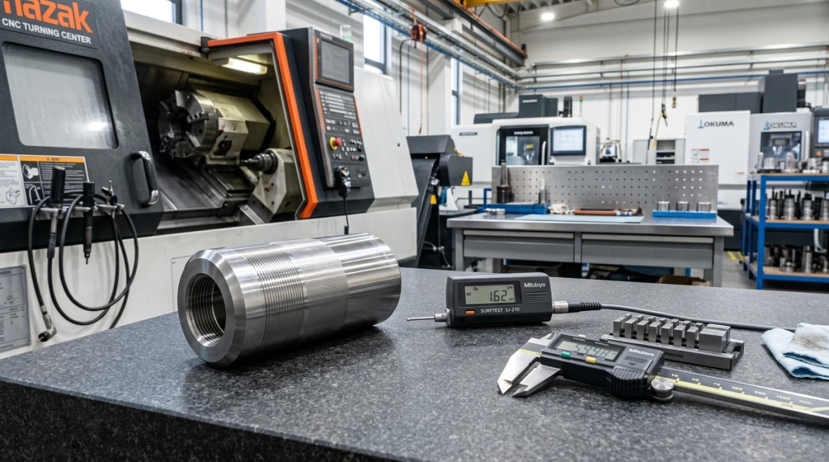
In stainless steel turning, customers do not reject every visible line. They reject the marks that violate drawing intent, compromise function, interfere with coating or sealing, or signal process instability. A part may still be dimensionally compliant within ±0.02 mm and yet be unusable because the turned face shows helical tearing, radial chatter, or a drag scratch across a critical contact band.
This matters most when the turned component serves as a bearing journal, valve seat, optical mount, medical fitting, sensor housing, or aerospace fluid interface. On these parts, the acceptable visual threshold is usually tied to a measurable finish requirement such as Ra 0.8 µm, Rz limits, waviness control, or a no-visible-scratch criterion at 300–500 lux under defined inspection distance. If no such standard is written into the drawing or quality plan, rejection risk rises sharply.
Procurement teams often discover too late that “good finish” means different things to different suppliers. One shop may consider fine tool feed lines acceptable on a 304 stainless shaft. Another may polish them out and change edge condition or diameter. Without explicit agreement, cosmetic disputes consume 2–3 review cycles, add 5–10 days to delivery, and create avoidable NCRs during incoming inspection.
The gap between visual rejection and engineering definition
The most reliable way to prevent disputes is to translate appearance into engineering checkpoints. That means defining which surfaces are cosmetic, functional, hidden, or post-processed, and assigning separate criteria to each. A hidden internal bore may accept standard turning marks at Ra 3.2 µm, while an external mating surface may require Ra 0.8 µm with no circumferential scoring deeper than a defined threshold.
For stainless alloys such as 303, 304, 316, 17-4PH, and duplex grades, machinability varies enough that finish quality should never be assumed to transfer directly between materials. A setup that produces a clean finish on free-machining 303 may generate built-up edge and torn grain on 316 if feed, speed, nose radius, and coolant delivery are not adjusted.
The table below connects common rejected marks to the real engineering concern they usually indicate.
The key conclusion is simple: surface rejection is easiest to manage when it is specified before production starts. Shops that measure finish, document tool life windows, and classify critical surfaces usually prevent the dispute that less structured suppliers try to solve through late polishing or subjective visual sorting.
The most common marks clients reject in custom stainless steel turning
Across precision turning programs, five categories appear most often in rejection reports: chatter, tearing, feed-line exaggeration, scratch damage, and thermal discoloration. Each has a distinct mechanism, and each should be handled differently in supplier audits and production planning. Treating all surface defects as one generic “finish issue” slows root-cause analysis and hides true process capability limits.
Chatter and harmonic banding
Chatter usually appears as repeating rings or wave patterns along the turned diameter. It is common on long, slender parts with L/D ratios above 3:1 or 5:1, especially in austenitic stainless grades that work harden quickly. Even when measured Ra appears acceptable, customers may reject these marks because waviness affects sealing, dynamic balance, or optical appearance under assembly lighting.
Why buyers should care
A supplier who cannot suppress chatter during first-pass turning may also struggle with repeatability at scale. For medium volumes of 500–2,000 pieces, this can turn into lot-to-lot finish variation, extra polishing labor, and hidden cycle-time inflation. That is why procurement reviews should ask not only for a sample photo, but also for documented spindle speed ranges, insert geometry, and support strategy such as tailstock or steady rest use.
Tearing, smearing, and built-up edge marks
Grades like 304 and 316 are notorious for producing smeared or torn surfaces when cutting edges wear or when chip formation becomes unstable. These marks are often misread as “minor finish variation,” but in high-spec parts they suggest rubbing, heat concentration, and a surface layer that may respond unpredictably in passivation or fatigue-sensitive use. For micro machining parts under 10 mm diameter, the margin for error becomes even smaller.
Handling scratches and chip drag damage
Not all rejected marks come from cutting. Many are created in the 30–90 minutes after machining, during binning, washing, deburring, or packaging. Stainless parts with polished or near-polished finishes are especially vulnerable. A supplier may have a stable turning process but still ship scratched components because finished parts contact each other in bulk trays or because chips remain in soft separators.
- Chatter indicates machine-system instability and usually requires process redesign, not cosmetic touch-up.
- Torn grain often points to insert wear, incorrect speed-feed balance, or work hardening in stainless stock.
- Straight scratches are frequently post-machining handling defects and should trigger packaging and flow review.
- Heat tint or local burnishing should prompt surface integrity review, especially before passivation or welding.
For end users and operators, this distinction matters because corrective action differs. For decision-makers, it matters because the right supplier is not merely the one with attractive samples, but the one able to separate machine-generated marks from logistics-generated damage and control both within a documented quality system.
What process gaps usually create those marks
Most rejected stainless turning surfaces can be traced to five measurable gaps: tool condition, parameter mismatch, rigidity loss, coolant failure, and uncontrolled post-processing. None are abstract. Each can be audited through setup sheets, in-process inspection, machine maintenance records, and sample-to-sample consistency. This is exactly where engineering-focused sourcing creates value over marketing-driven supplier selection.
Cutting parameter mismatch
When feed rate, depth of cut, and surface speed are not aligned to the stainless grade, the result is often exaggerated feed marks or smeared finishes. For many stainless turning operations, suppliers tune within broad but practical windows, such as lower-to-moderate cutting speeds for tougher grades and feed adjustments based on required Ra. On fine-finish passes, even a small feed change can move a part from acceptable to visually rejectable.
Rigidity, runout, and workholding distortion
A part that is clamped too aggressively may show jaw pressure distortion, while one that is under-supported may chatter or taper. On thin-wall stainless sleeves, even 0.02–0.05 mm of elastic distortion during chucking can alter contact and create inconsistent finish bands. Buyers of micro machining tolerance parts should specifically ask how the supplier handles thin-wall, long-shaft, and interrupted cut geometries.
Coolant application and chip evacuation
Stainless steel generates tenacious chips and concentrated heat. If coolant pressure, nozzle direction, or filtration is poor, chips recut the surface and create drag lines that inspection teams later classify as scratches. This is common in unattended or lights-out runs longer than 2–4 hours, where chip accumulation gradually degrades finish before dimension trends visibly move out of tolerance.
The table below helps buyers connect root causes with practical supplier questions during RFQ and technical review.
A consistent pattern emerges: shops that can answer these questions with process details usually produce fewer cosmetic claims. Shops that answer only with general assurances often rely on manual sorting and reactive rework, which is expensive, difficult to scale, and risky for regulated applications.
Where EDM and secondary finishing enter the picture
Some stainless components combine turning with EDM, grinding, or polishing. In those cases, buyers should not evaluate the turned finish in isolation. EDM surface integrity analysis matters because recast layer, heat-affected zone behavior, or edge transitions can change how a turned feature looks after secondary processing. The same applies to 5 axis cnc surface finish Ra targets on hybrid parts where multiple processes meet on one visible face.
How to define acceptable finish in drawings, RFQs, and supplier audits
The fastest route to repeated cosmetic disputes is vague documentation. Terms such as “smooth finish,” “no marks,” or “high-quality appearance” do not survive production reality. Buyers should define finish by surface category, numerical requirement, inspection method, and viewing condition. That approach reduces interpretation gaps between engineers, suppliers, inspectors, and end users.
Use layered acceptance criteria
A robust print or quality note often separates requirements into at least 3 layers: functional surfaces, cosmetic surfaces, and non-critical surfaces. Functional surfaces may specify Ra, roundness, or no circumferential scoring. Cosmetic surfaces may add a visual standard under defined light and distance. Non-critical surfaces may accept standard machining witness marks if burr-free and corrosion-ready.
Specify inspection and sample approval up front
For new programs, it is wise to lock finish expectations through first article approval or a golden sample before volume production. In practice, this can save 1–2 procurement cycles and prevent recurring debate over borderline parts. If the part is highly cosmetic, request macro photos, profilometer readings, and documentation of the finishing route after passivation, electropolishing, or manual blend operations.
Recommended RFQ checkpoints
- Identify all critical turned surfaces and label them as functional, sealing, visible, or hidden.
- Assign measurable finish targets such as Ra 0.8 µm, 1.6 µm, or 3.2 µm instead of general wording.
- Define whether fine feed lines are acceptable and under what lighting or viewing distance they are judged.
- Request supplier disclosure of tool life control, handling flow, and packaging separation method.
- Require a first article or pilot lot review for parts with micro machining tolerance or visible Class A surfaces.
These checkpoints are especially important when sourcing from an aerospace CNC turning factory or from suppliers serving medical and instrumentation sectors. In those environments, cosmetic quality often overlaps with traceability, cleanliness, and process validation. A polished sample alone is not enough; the supplier must prove that the same result is sustainable across lot sizes, operator shifts, and machine platforms.
For decision-makers, the hidden financial issue is clear: a part rejected for appearance after shipment usually costs far more than a part rejected during pilot approval. Freight, quarantine time, line stoppage exposure, and engineering review can multiply the original machining value by 3–5 times in total disruption cost.
Practical selection criteria for buyers, operators, and engineering teams
Supplier selection should focus on controllability, not promises. The best custom stainless steel turning partner is usually the one who can show how finish is produced, measured, protected, and repeated. That means documented process windows, surface metrology access, change control, and packaging discipline. It also means honest communication about what finish level is realistic for a given alloy and geometry.
A practical evaluation framework
Use four filters during qualification: capability, consistency, protection, and communication. Capability asks whether the supplier can hit the required Ra and tolerance. Consistency asks whether they can hold it over 50, 500, or 5,000 pieces. Protection asks whether the finish survives washing and shipment. Communication asks whether they translate risk clearly before production begins.
The matrix below can support sourcing decisions when appearance risk is high.
For operators and quality engineers, the lesson is equally practical. If a part requires both micro machining tolerance and premium appearance, process capability must be built into the route sheet, not inspected in at the end. The more critical the surface, the less room there is for rescue operations such as manual buffing, especially on edges, sealing lands, and precision diameters.
When to escalate to a deeper technical review
Escalate early if the part combines any of the following: wall thickness below 1.5 mm, diameter below 6 mm, Ra requirement under 0.8 µm, visible external finish after passivation, or mixed processing that includes EDM or 5-axis milling. These combinations increase the odds that a cosmetic complaint is actually a signal of deeper surface integrity or process stability risk.
FAQ and next-step guidance for reducing rejection risk
Teams sourcing custom stainless steel turning often ask similar questions because the same failures repeat across industries: unclear standards, overreliance on visual judgment, and insufficient supplier process disclosure. The answers below can help convert vague concerns into actionable technical requirements.
How smooth does a turned stainless surface need to be?
It depends on function. General non-critical turned surfaces may accept Ra 1.6–3.2 µm. Sealing, bearing, or premium cosmetic zones often target Ra 0.4–0.8 µm. The important point is to define the requirement by surface, not by part as a whole. One component may legitimately contain three different finish classes.
Can polishing solve all rejected marks?
No. Polishing may hide light feed marks or minor handling lines, but it can also change geometry, soften edges, or mask a deeper process problem. If chatter, tearing, or heat damage is the root cause, polishing is usually a short-term cosmetic patch rather than a sustainable correction.
What should procurement request before placing a production order?
At minimum, request finish criteria by surface, sample approval or first article review, metrology method, handling and packaging plan, and lead-time assumptions for prototype versus repeat order. For critical applications, ask how the supplier manages insert life, chip evacuation, and secondary processes that may affect final appearance.
How long does finish-related corrective action usually take?
If the issue is packaging or handling, corrective action can sometimes be implemented in 2–5 working days. If the issue is chatter, tool wear behavior, or an unstable process window, a proper fix may require a new trial cycle, revised tooling, and 1–2 weeks of validation depending on part complexity and machine availability.
Surface marks clients reject are rarely random. They are engineering signals. When buyers, engineers, and suppliers define those signals with measurable finish targets, realistic tolerance interaction, and controlled handling standards, cosmetic complaints stop being subjective debates and become manageable process variables. If your team is qualifying a stainless turning supplier, reviewing a rejected lot, or drafting tighter appearance criteria for aerospace, robotics, medical, or industrial hardware programs, now is the right time to turn those requirements into a clear technical specification. Contact us to discuss your custom part scenario, request a more precise evaluation framework, or explore a tailored sourcing and quality-control strategy.
Search News
Hot Articles
- Carbon Fiber StructuresHow to Specify Aerospace Carbon Fiber Assemblies for Lightweight, Load-Bearing PartsJul 11, 2026
- Machine VisionXiaomi, Alibaba DAMO Academy Drive Open-Source Robotics Model Ecosystem, Lowering Algorithm Development Barriers for Overseas SMEs Adopting Chinese Robotics SolutionsMar 30, 2026
- Cobots & ArmsShanxi 'AI+' Conference Showcases Embodied Intelligence with Multinational Buyer Engagement: Key Industry ImplicationsMar 30, 2026
Popular Tags
Recommended News
 Jul 11, 2026How to Specify Aerospace Carbon Fiber Assemblies for Lightweight, Load-Bearing PartsAerospace carbon fiber assemblies: learn how to specify laminate design, load data, joining methods, and inspection controls for lighter, reliable load-bearing aerospace parts.Elena Rostova (UAV Systems Researcher)
 Mar 30, 2026Xiaomi, Alibaba DAMO Academy Drive Open-Source Robotics Model Ecosystem, Lowering Algorithm Development Barriers for Overseas SMEs Adopting Chinese Robotics SolutionsXiaomi & Alibaba DAMO Academy's open-source robotics models lower algorithm barriers for global SMEs. Boost efficiency in manufacturing, logistics & smart retail with ROS 2 compatible solutions.TSV Data Lab
 Mar 30, 2026Shanxi 'AI+' Conference Showcases Embodied Intelligence with Multinational Buyer Engagement: Key Industry ImplicationsShanxi 'AI+' Conference highlights embodied intelligence with Tesla, Ubtech & Jiantao showcasing multimodal robotics. 40+ global buyers validated tech on-site, creating new B2B channels for industrial automation & AI solutions.Chen Wei (Automation Lead Engineer)
 Mar 30, 2026Zhongguancun Unveils 6G Integrated Sensing-Computing-Intelligence Platform to Empower Embodied Robots for Global Industrial ApplicationsZhongguancun's new 6G platform revolutionizes industrial robotics with <10ms latency, empowering global automotive, logistics & port automation. Discover how this tech boosts China's smart manufacturing exports.TSV Data Lab
 Mar 30, 2026Mech-Mind Tianjin Embodied Intelligence R&D and Production Base Goes Live, Cutting Delivery Time by 20%–30% for Global Customized AMR+Vision SolutionsMech-Mind's Tianjin AMR+Vision production base cuts delivery time by 20%-30% for欧美 & Latin American markets. Discover how this PLd-certified facility accelerates customized robotics solutions for smart manufacturing and logistics.Chen Wei (Automation Lead Engineer)
 Mar 30, 2026Boao Forum Reveals 'Co-evolution of Big and Small Brains' Trend in Humanoid Robots, China's Embodied Intelligence Accelerates Adaptation to Overseas Manufacturing Service ScenariosDiscover how China's humanoid robots, featuring 'Co-evolution of Big and Small Brains,' are revolutionizing global manufacturing. Learn about Embodied Tian Gong 3.0's ISO compliance and overseas deployment at Boao Forum 2026.Chen Wei (Automation Lead Engineer)
 Mar 30, 2026China Railway Industrial Secures Patent for Embodied Robotics in Material Handling, Boosting High-Precision Delivery Capabilities for Overseas Infrastructure and Manufacturing ProjectsChina Railway Industrial's new patent for embodied robotics in material handling boosts high-precision delivery for global infrastructure & manufacturing. Discover how this innovation enhances logistics accuracy in automotive, rail transit & EPC projects.Chen Wei (Automation Lead Engineer)
 Oct 27, 2026GXO and Agility Robotics Expand Partnership to Accelerate US Humanoid Robot DeploymentGXO and Agility Robotics plan to expand US humanoid robot deployment with Digit 4 in early 2027. Explore warehouse automation plans, service terms and future Digit 5 upgrades.Chen Wei (Automation Lead Engineer)
 Oct 27, 2026Robotic Automation Costs: Budgeting for Equipment, Integration, and MaintenancePlan your robotics automation cost with confidence. Explore equipment, integration, and maintenance expenses, compare quotes, and build a realistic budget for better ROI.Chen Wei (Automation Lead Engineer)
 Oct 26, 2026AMAXiMAL Releases Open-Source TopMod 3D v3 With Claude AIExplore AMAXiMAL’s free, open-source TopMod 3D v3 with Claude AI assistance, topology-based modeling and plywood fabrication tools that connect complex designs to physical builds.Dr. Marcus Vance
 Oct 26, 2026Choosing a SCADA System Integrator Company: PLC Compatibility and Long-Term SupportChoose a scada system integrator company with proven PLC compatibility and reliable long-term support. Discover what to test, compare, and require before investing.Victor Lin (Chief Software Architect)
 Oct 25, 2026Hesai Leads Global ADAS Main Lidar Shipments in Yole’s 2026 ReportHesai led global ADAS main lidar shipments with a 43% share in 2025, according to Yole’s 2026 report. Explore what this ranking reveals about its automotive market position.TSV Data Lab
 Oct 25, 2026Choosing an Aerospace Materials Manufacturer: Quality and Traceability ChecksChoosing an aerospace materials manufacturer? Learn how to verify certifications, test reports, and lot traceability to qualify suppliers confidently and reduce costly sourcing risks.Dr. Marcus Vance
 Oct 24, 2026Guotai Haitong: Global Entry-Level 3D Printer Shipments Rose 39% in Q1 2026Entry-level 3D printer shipments rose 39% in Q1 2026, Guotai Haitong reports. Explore how AI, multicolor printing and print farms are shaping market growth.Dr. Marcus Vance
 Oct 24, 2026Choosing an Industrial Vision Inspection Supplier: Acceptance Tests That MatterChoose an industrial vision inspection supplier with confidence. Discover acceptance tests for defect detection, false rejects, production speed, and reliable part rejection before you buy.TSV Data Lab
 Oct 23, 2026US Navy Raises Gecko Robotics Contract Ceiling to $300M for Robotic Fleet MaintenanceUS Navy raises Gecko Robotics’ contract ceiling to $300M for Pacific Fleet robotic inspections. Explore potential opportunities for maintenance suppliers and key procurement considerations.Chen Wei (Automation Lead Engineer)
 Oct 23, 2026Choosing Industrial Sensing Systems for Global Plants: Protocol CompatibilityCompare industrial sensing systems international buyers can trust. Explore protocol compatibility, reduce integration risks, and select proven configurations for reliable global plant deployments.TSV Data Lab
 Oct 22, 2026KUKA Showcases Physical AI and iiQKA.AI Vision at NVIDIA GTC BerlinExplore KUKA’s Physical AI showcase at NVIDIA GTC Berlin and discover how iiQKA.AI Vision aims to simplify robotic vision integration and improve 2D and 3D scene recognition.TSV Data Lab
 Oct 22, 2026Robotic Machining of Advanced Composites: What Tolerances Are Achievable?Explore advanced materials machining robotics: discover what drives achievable composite tolerances and how to validate accuracy before investing in your next machining system.Dr. Marcus Vance
 Oct 21, 2026China’s Industrial Robot Exports Near RMB 10 Billion in First Nine Months of 2026China’s industrial robot exports neared RMB 10 billion in January–September 2026, with value rising faster than volume. Explore the data and what it could mean for suppliers.Chen Wei (Automation Lead Engineer)
 Oct 21, 2026Low-Latency Industrial Data Processing: Pricing and Key Cost DriversExplore industrial data latency price drivers, from edge hardware to integration and support. Learn how to compare quotes, verify performance, and avoid unnecessary costs.TSV Data Lab
 Oct 20, 2026KUKA Launches iiQKA.AI Vision to Simplify Industrial Image ProcessingKUKA iiQKA.AI Vision simplifies industrial image processing with controller-based 2D and 3D vision. Explore drag-and-drop setup for vision-guided automation.TSV Data Lab
 Oct 20, 2026Smart Industrial Edge Devices: Key Criteria for Legacy PLC IntegrationChoose smart industrial edge devices for legacy PLC integration. Discover key criteria for compatibility, data quality, security, and reliable collection without disrupting control.TSV Data Lab
 Oct 19, 2026Choosing a Radar Sensor by Application: Range, Resolution, and Field of ViewSimplify radar sensor application based product selection. Compare range, resolution, and field of view to avoid blind spots and choose with confidence. Explore the guide.TSV Data Lab