Why 5 axis CNC is critical for stable impeller geometry
Publication Date
author
For enterprise buyers and engineering leaders, stable impeller geometry is not a cosmetic advantage—it directly shapes aerodynamic efficiency, balance, fatigue life, and certification confidence. That is why 5 axis CNC for aerospace impellers has become a critical benchmark in precision manufacturing: it enables consistent blade profiles, tighter tolerance control, and fewer cumulative errors across complex curved surfaces, where even minor deviation can compromise downstream system performance.
In aerospace, UAV propulsion, turbo machinery, and high-speed fluid systems, impellers operate in environments where rotational speed can exceed 20,000 rpm and where geometry errors measured in tenths of a millimeter may trigger vibration, airflow instability, or premature wear. For decision-makers evaluating suppliers, the issue is not whether a shop owns advanced equipment, but whether it can repeatedly convert CAD intent into verifiable, inspection-ready parts.
This is where the logic behind TechStat Vanguard matters. Data, tolerances, process control, and traceability carry more procurement value than broad claims about quality. When buyers assess 5 axis CNC for aerospace impellers, they are effectively assessing a supplier’s ability to manage blade continuity, hub-to-shroud transitions, toolpath stability, setup reduction, and inspection discipline across the full production cycle.
Why stable impeller geometry is a procurement-level requirement

Stable geometry means more than producing a part that visually matches a drawing. For aerospace impellers, it means maintaining consistent blade angle, surface continuity, wall thickness, root fillet integrity, and concentricity from the first part to the fiftieth. In most buyer evaluations, 4 technical outcomes matter most: aerodynamic repeatability, rotor balance, fatigue resistance, and downstream assembly confidence.
Small deviations create large system consequences
A 0.05 mm variation in blade thickness or an angular deviation across multiple blades can shift airflow behavior enough to affect efficiency and noise. At high rotational speeds, even minor asymmetry may increase dynamic imbalance, forcing extra balancing operations or reducing service life. For procurement teams, this translates into hidden cost: more incoming inspection, more rework, and greater qualification risk.
In practical sourcing terms, geometry instability increases three exposure points. First, scrap rates rise when thin blades or deep channels are machined inconsistently. Second, lead times stretch when manual adjustment and secondary finishing are required. Third, compliance risk grows when dimensional reports cannot demonstrate repeatability across batches of 10, 20, or 100 pieces.
Why 3-axis and indexed machining often fall short
Many impeller profiles feature twisted blades, undercut regions, and tight internal flow passages. In 3-axis machining, access limitations often require multiple setups, custom fixtures, or hand blending. Each added setup introduces another alignment variable. If a part needs 3 to 5 re-clamp operations, cumulative positional error can quickly exceed the tolerance stack allowed for aerospace-grade rotating components.
Indexed 3+2 machining improves access, but it still cannot fully match the continuous interpolation needed for complex blade surfaces. For buyers comparing manufacturing routes, the core question is whether the process preserves the intended geometry continuously, not in segmented approximations. That distinction is why 5 axis CNC for aerospace impellers is increasingly treated as a baseline requirement rather than a premium option.
Typical risk indicators during supplier review
- More than 2 major setup changes for one impeller
- Heavy dependence on manual polishing to correct blade form
- No clear blade-to-blade deviation report
- Inspection limited to basic diameters and overall height
- No defined process for tool wear compensation on thin features
The table below shows why different machining approaches produce very different outcomes for high-value impeller programs.
For enterprise sourcing, fewer setups usually mean more than shorter cycle time. They mean a lower probability of geometric drift between operations, which is especially important for closed impellers, blisks, and thin-wall rotor components with narrow tolerance windows.
How 5-axis CNC protects blade accuracy and process stability
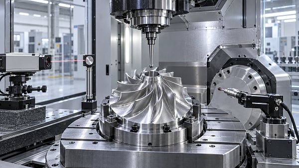
The value of 5 axis CNC for aerospace impellers comes from its ability to align tool orientation with changing blade curvature throughout the cut. Instead of forcing the part into a limited tool approach, simultaneous motion across 5 axes lets the machine maintain better cutter engagement, improve access to difficult regions, and reduce overcut or scallop inconsistency on complex surfaces.
Continuous tool engagement improves surface fidelity
In impeller machining, blade channels often include steep walls, narrow spacing, and varying camber. A 5-axis machine can keep the cutter at a more stable contact angle, reducing sudden load changes that may distort thin features. In many practical programs, this helps maintain surface finish targets such as Ra 0.8–1.6 μm before any light post-processing, depending on material and geometry.
Stable tool engagement also supports predictable tool life. When a supplier can control cutting forces more consistently, it becomes easier to maintain repeatable blade profiles from part 1 to part 30. For buyers, that means fewer surprises in serial production and a more credible path from prototype validation to low- or mid-volume delivery.
Fewer setups reduce tolerance stack-up
Each time a part is removed and repositioned, datums must be re-established. Even when fixtures are precise, setup transfer introduces uncertainty. For components where profile tolerance, runout, and concentricity interact, eliminating 2 or 3 extra setups can significantly improve process capability. This is why leading suppliers often aim to complete most impeller features in 1 primary setup and 1 controlled secondary operation at most.
Core technical advantages buyers should verify
- Simultaneous 5-axis interpolation, not just indexed movement
- CAM strategy optimized for blade surfaces and hub transitions
- Stable toolpath simulation for collision avoidance in tight channels
- In-process probing or datum verification between operations
- Inspection coverage for profile, runout, thickness, and balance-related geometry
The next table highlights the machining variables that matter most when evaluating 5 axis CNC for aerospace impellers at the procurement stage.
These ranges are not universal promises, because material type, impeller diameter, blade count, and shroud condition all influence final capability. However, they provide a practical benchmark for supplier comparison and technical discussion during RFQ review.
What enterprise buyers should ask before awarding an impeller program
A capable supplier should be able to discuss process control in concrete terms. Buyers should move beyond asking whether the machine is 5-axis and ask how the supplier manages verification, tool strategy, fixture design, and batch repeatability. This is especially important in aerospace-adjacent and UAV programs where development schedules are compressed and validation windows may be limited to 2–6 weeks.
Five questions that reveal real capability
- Can you share the planned setup sequence and datum strategy for this geometry?
- Which blade features are controlled by CMM profile checks, and which by surface scanning?
- How do you manage tool wear compensation on thin or deep-channel sections?
- What is the expected lead time for first article, rework loop, and repeat batch release?
- Which standards guide your documentation flow, such as AS9100-style traceability practices?
These questions matter because many sourcing failures come from process ambiguity rather than machine limitations. A supplier may have a high-end machine but still lack robust programming discipline or inspection structure. For enterprise teams, a clean technical answer often predicts smoother execution better than a polished sales presentation.
Procurement signals beyond unit price
Unit price is only one variable in impeller procurement. If a lower quote introduces longer validation time, extra balancing work, or 2 additional supplier visits, total program cost rises quickly. A more useful comparison combines 4 dimensions: geometric capability, documentation quality, delivery reliability, and change-response speed.
For prototype or pre-production programs, buyers should also check whether the supplier can support fast engineering feedback. A strong partner can typically review manufacturability within 24–72 hours, flag risky blade geometry early, and suggest adjustments that preserve performance while improving machining stability.
Recommended qualification checklist
- Review CAD complexity, alloy type, and critical profile tolerances
- Confirm simultaneous 5-axis process route and fixture approach
- Define inspection plan for at least 6 critical dimensions or profiles
- Request sample reporting format before production starts
- Align on first article timing, revision control, and nonconformance handling
Implementation risks, quality controls, and long-term sourcing value
Even with the right machine architecture, stable impeller geometry depends on execution discipline. Material movement, thermal variation, tool deflection, and post-machining handling can all affect the final result. This is why advanced buyers treat 5 axis CNC for aerospace impellers as a process ecosystem, not just a machine specification.
Common failure points in impeller programs
One common issue is overreliance on manual finishing. If a blade surface requires heavy hand correction, geometric consistency becomes difficult to prove. Another issue is incomplete measurement strategy. Inspecting only outer diameter, bore, and height may miss blade-to-blade variation, root fillet deviation, or local thickness drift in critical aerodynamic regions.
Thermal control also matters. In precision environments, even a few degrees of temperature variation can influence both machining and measurement. Buyers do not need laboratory perfection in every case, but they should expect clear control practices, especially when tolerance bands approach ±0.02 mm on critical surfaces.
How stronger process control reduces supplier risk
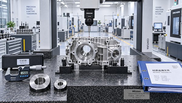
The most reliable suppliers build repeatability through documented steps: CAM verification, fixture validation, in-process checks, final CMM inspection, and revision traceability. This structure shortens supplier qualification cycles because technical confidence accumulates faster. For global buyers managing multi-site development, better traceability also supports cleaner communication between design, procurement, and quality teams.
This approach aligns with TSV’s broader view of hard-tech sourcing. The right manufacturing partner should provide measurable engineering truth: tolerance ranges, process limits, inspection logic, and realistic lead-time windows such as 2–4 weeks for prototypes or 4–8 weeks for more complex qualified batches, depending on material and documentation requirements.
Practical buyer recommendations
- Use profile and repeatability data to compare suppliers, not machine brand alone
- Prioritize suppliers that can explain setup reduction and datum protection clearly
- Ask for inspection evidence on blade geometry, not only basic dimensional reports
- Align quality expectations before PO release to avoid costly revision loops
- Evaluate total program risk across cost, lead time, compliance, and scalability
For enterprises sourcing flight-critical or high-speed rotating parts, geometry stability is a commercial issue as much as a technical one. Better geometry control supports lower rework, fewer supplier disputes, and stronger confidence during design freeze, pilot build, and production transfer.
5 axis CNC for aerospace impellers is critical because it directly supports the outcomes decision-makers care about most: repeatable blade accuracy, lower tolerance stack-up, stronger inspection confidence, and more predictable program execution. In a market crowded with broad claims, the smarter sourcing path is to verify process logic, measurable capability, and traceable quality controls. If your team is evaluating impeller suppliers, refining a specification sheet, or comparing machining routes for complex rotating components, contact us to discuss your application, review technical requirements, and explore a more data-driven manufacturing strategy.
Search News
Hot Articles
- Carbon Fiber StructuresHow to Specify Aerospace Carbon Fiber Assemblies for Lightweight, Load-Bearing PartsJul 11, 2026
- Machine VisionXiaomi, Alibaba DAMO Academy Drive Open-Source Robotics Model Ecosystem, Lowering Algorithm Development Barriers for Overseas SMEs Adopting Chinese Robotics SolutionsMar 30, 2026
- Cobots & ArmsShanxi 'AI+' Conference Showcases Embodied Intelligence with Multinational Buyer Engagement: Key Industry ImplicationsMar 30, 2026
Popular Tags
Recommended News
 Jul 11, 2026How to Specify Aerospace Carbon Fiber Assemblies for Lightweight, Load-Bearing PartsAerospace carbon fiber assemblies: learn how to specify laminate design, load data, joining methods, and inspection controls for lighter, reliable load-bearing aerospace parts.Elena Rostova (UAV Systems Researcher)
 Mar 30, 2026Xiaomi, Alibaba DAMO Academy Drive Open-Source Robotics Model Ecosystem, Lowering Algorithm Development Barriers for Overseas SMEs Adopting Chinese Robotics SolutionsXiaomi & Alibaba DAMO Academy's open-source robotics models lower algorithm barriers for global SMEs. Boost efficiency in manufacturing, logistics & smart retail with ROS 2 compatible solutions.TSV Data Lab
 Mar 30, 2026Shanxi 'AI+' Conference Showcases Embodied Intelligence with Multinational Buyer Engagement: Key Industry ImplicationsShanxi 'AI+' Conference highlights embodied intelligence with Tesla, Ubtech & Jiantao showcasing multimodal robotics. 40+ global buyers validated tech on-site, creating new B2B channels for industrial automation & AI solutions.Chen Wei (Automation Lead Engineer)
 Mar 30, 2026Zhongguancun Unveils 6G Integrated Sensing-Computing-Intelligence Platform to Empower Embodied Robots for Global Industrial ApplicationsZhongguancun's new 6G platform revolutionizes industrial robotics with <10ms latency, empowering global automotive, logistics & port automation. Discover how this tech boosts China's smart manufacturing exports.TSV Data Lab
 Mar 30, 2026Mech-Mind Tianjin Embodied Intelligence R&D and Production Base Goes Live, Cutting Delivery Time by 20%–30% for Global Customized AMR+Vision SolutionsMech-Mind's Tianjin AMR+Vision production base cuts delivery time by 20%-30% for欧美 & Latin American markets. Discover how this PLd-certified facility accelerates customized robotics solutions for smart manufacturing and logistics.Chen Wei (Automation Lead Engineer)
 Mar 30, 2026Boao Forum Reveals 'Co-evolution of Big and Small Brains' Trend in Humanoid Robots, China's Embodied Intelligence Accelerates Adaptation to Overseas Manufacturing Service ScenariosDiscover how China's humanoid robots, featuring 'Co-evolution of Big and Small Brains,' are revolutionizing global manufacturing. Learn about Embodied Tian Gong 3.0's ISO compliance and overseas deployment at Boao Forum 2026.Chen Wei (Automation Lead Engineer)
 Mar 30, 2026China Railway Industrial Secures Patent for Embodied Robotics in Material Handling, Boosting High-Precision Delivery Capabilities for Overseas Infrastructure and Manufacturing ProjectsChina Railway Industrial's new patent for embodied robotics in material handling boosts high-precision delivery for global infrastructure & manufacturing. Discover how this innovation enhances logistics accuracy in automotive, rail transit & EPC projects.Chen Wei (Automation Lead Engineer)
 Oct 04, 2026CAD/CAM Benchmarking in the GCC: What Manufacturers Should Ask a ConsultantCAD CAM benchmark consultant GCC guide: learn the key questions manufacturers should ask to validate post-processors, workflows, machine performance, and production risk.Victor Lin (Chief Software Architect)
 Oct 03, 2026Selecting Automotive Radar Sensor Modules for ADAS Range, Resolution, and IntegrationAutomotive radar sensor module selection guide for ADAS: compare range, resolution, field of view, latency, and integration to build safer, reliable vehicle systems.TSV Data Lab
 Oct 02, 2026How to Qualify Machined Parts Suppliers for Hard Tech ProgramsHard tech supply chain machined parts demand rigorous supplier qualification. Learn how to assess capability, traceability, quality controls, and delivery resilience.Dr. Marcus Vance
 Oct 01, 2026How to Select an Outdoor Security Radar Sensor for Perimeter Detection?Outdoor security radar sensor selection guide: compare range, accuracy, false-alarm control, integration, and field testing for reliable perimeter detection.TSV Data Lab
 Sep 30, 2026How to Evaluate Solid-State LiDAR Hardware for Outdoor Autonomous VehiclesSolid state LiDAR hardware evaluation guide for outdoor autonomous vehicles—compare range, point-cloud quality, environmental resilience, integration, and safety.TSV Data Lab
 Sep 29, 2026ISO 9283 Repeatability: How to Evaluate Cobot Positioning PerformanceISO 9283 cobot repeatability explained: learn how payload, reach, approach direction, and test conditions affect positioning performance and cell capability.Chen Wei (Automation Lead Engineer)
 Oct 04, 2026How Should You Compare 5-Axis CNC Machine Accuracy Claims?How do I compare 5-axis CNC machine accuracy claims? Learn how to assess standards, thermal stability, TCP accuracy, and real-world test evidence.Dr. Marcus Vance
 Oct 03, 2026Is Edge Computing Necessary for Real-Time Quality Inspection?Is industrial edge computing necessary for real-time quality inspection? Explore how latency, data volume, reliability, and control integration shape the right architecture.TSV Data Lab
 Oct 02, 2026What Documents Prove a Precision Machining Supplier Can Hold Tolerance?What documents prove a precision machining supplier can hold tolerance? Explore certificates, FAI reports, calibration, SPC, and traceability evidence to qualify suppliers with confidence.Dr. Marcus Vance
 Oct 01, 2026Can a Machining Supplier Meet Aerospace Fatigue Testing Requirements?Can a machining supplier meet aerospace fatigue testing requirements? Learn the traceability, process control, and test evidence needed for reliable aerospace parts.Dr. Marcus Vance
 Sep 30, 2026Which Industrial Robot Specifications Matter for High-Precision Assembly?Which industrial robot specifications matter most for high-precision assembly? Explore repeatability, accuracy, stiffness, vibration, calibration, and force control for reliable yields.Chen Wei (Automation Lead Engineer)
 Sep 29, 2026How Do You Verify Servo Motor Torque Under Continuous Load?How do I verify servo motor torque under continuous load? Learn RMS torque checks, torque-speed limits, thermal derating, and real-machine testing.Chen Wei (Automation Lead Engineer)
 Oct 02, 2026ZD330 Software Configuration: Verifying Cut-List Import Before PurchaseZD330 software and machine configuration: verify cut-list imports, data mapping, labels, and workflow before purchase to reduce errors and choose with confidence.Victor Lin (Chief Software Architect)
 Sep 28, 2026Spindle Runout Measurement in Germany: DIN Standards, Methods, and Acceptance LimitsSpindle runout measurement Germany: explore DIN standards, proven methods, acceptance limits, and audit-ready practices for reliable machining quality.Dr. Marcus Vance
 Sep 27, 2026How to Select Wall-Mount Edge Devices for Space-Constrained Factory NetworksWall mount edge devices for space-constrained factories: evaluate workload, thermal design, power resilience, cable access, and network reliability for smarter deployments.TSV Data Lab
 Sep 26, 2026Machining Tolerance Analysis: How to Set Limits That Meet Function and Cost TargetsMachining tolerance analysis: learn how to set functional limits, control tolerance stacks, reduce inspection risk, and balance precision with production cost.Dr. Marcus Vance
 Sep 25, 2026How to Evaluate an Industrial Infrastructure Data Platform for Multi-Site OperationsIndustrial infrastructure data platform evaluation guide for multi-site operations: compare data quality, edge resilience, interoperability, governance, and scalable proof-of-value criteria.Victor Lin (Chief Software Architect)