What affects 5 axis CNC surface finish Ra the most
Publication Date
author
For engineers, buyers, and technical leaders, the biggest driver of 5 axis CNC surface finish Ra is rarely one variable alone. It is the combined effect of tool wear, machine dynamics, material behavior, and cnc milling chatter frequency analysis. From titanium grade 5 machinability to inconel 718 tool wear rate and micro machining tolerance limits, understanding these factors is essential for selecting the right process, supplier, and performance standard.
In practical sourcing and production, Ra is not just a cosmetic number on a drawing. It affects sealing performance, fatigue life, coating adhesion, friction behavior, and downstream inspection yield. For aerospace, medical, robotics, UAV, and precision equipment programs, a difference between Ra 0.4 μm and Ra 1.6 μm can change post-processing cost, cycle time, and acceptance risk.
This is why surface finish on 5 axis CNC parts should be evaluated through measurable engineering inputs rather than marketing claims. A supplier may quote tight tolerances such as ±0.01 mm, but if spindle vibration, toolpath strategy, and material-specific cutting parameters are poorly controlled, the final surface may still fail functional requirements. For procurement teams and decision-makers, knowing what affects Ra the most improves supplier qualification and reduces trial-and-error cost.
The Primary Process Variables That Control 5 Axis CNC Surface Finish Ra
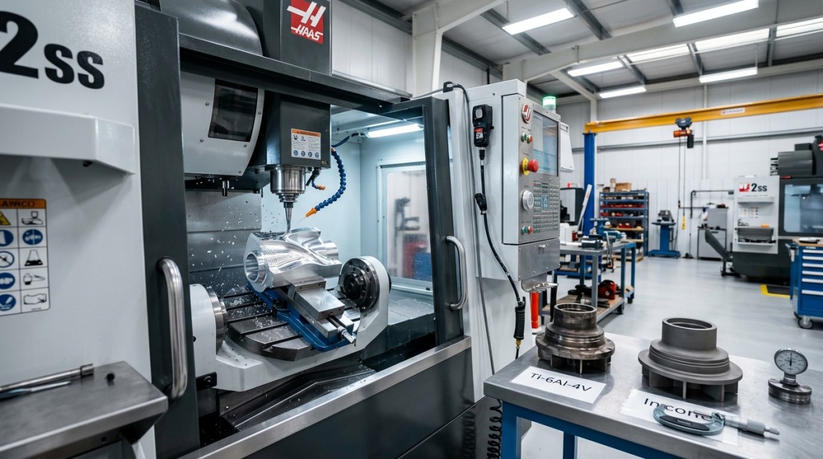
The most influential variables usually fall into four groups: cutting tool condition, machine stability, cutting parameters, and workpiece material behavior. In 5 axis machining, these factors interact more strongly than in 3 axis milling because tool orientation, simultaneous rotary motion, and changing contact points alter chip thickness and force direction throughout the cut.
Tool wear is often the fastest route to rising Ra. A fresh tool may hold a stable finish for the first 20 to 60 minutes of cutting on aluminum, but on titanium grade 5 or Inconel 718, edge degradation can begin much sooner depending on speed, coolant delivery, and radial engagement. Once flank wear grows, the tool rubs instead of shearing cleanly, leaving smearing, tearing, and localized peaks on the surface.
Machine dynamics matter just as much. Even when nominal feed per tooth and spindle speed look correct, weak fixturing, spindle imbalance, axis backlash, or servo tuning issues can create vibration bands that increase roughness. In multi-axis finishing, a machine with higher dynamic stiffness can often produce lower Ra at the same programmed step-over because it suppresses micro chatter at frequencies that would otherwise print into the surface.
Cutting parameters must be evaluated as a system rather than isolated values. Feed per tooth, spindle speed, axial depth, radial width, and toolpath smoothing all shape scallop height and heat generation. For example, reducing step-over from 0.3 mm to 0.1 mm may significantly improve finish on a freeform surface, but if spindle speed is too high for the material, built-up edge or thermal softening can still degrade Ra.
Material response is the fourth core variable. Aluminum alloys often allow Ra below 0.8 μm under stable finishing conditions, while titanium and nickel-based alloys may require lower feed, sharper tools, or secondary finishing to approach the same level. Hardness variation, grain structure, residual stress, and heat conductivity all influence how the material cuts and what the final topography looks like.
How these variables typically rank in production
The table below provides a practical ranking for engineers and sourcing teams evaluating why 5 axis CNC surface finish Ra varies between suppliers or between production lots.
For most high-value parts, tool condition and machine dynamics are the first two variables to verify. If those are unstable, parameter tuning alone rarely delivers repeatable Ra. This is particularly important in B2B supplier audits, where sample quality can look acceptable, but batch consistency over 50, 200, or 1,000 parts tells a very different story.
Why Material Behavior Changes Surface Finish More Than Many Buyers Expect
Material choice often sets the lower practical limit for achievable Ra before process optimization even begins. Buyers sometimes compare quotations across aluminum, stainless steel, titanium grade 5, and Inconel 718 using the same finish target, but these alloys do not respond the same way under identical machining conditions. Heat resistance, work hardening, elasticity, and thermal conductivity change both tool wear rate and surface generation mechanism.
Titanium grade 5 machinability is a common challenge in aerospace and UAV structures. Because titanium retains heat near the cutting zone and has relatively low thermal conductivity, the tool edge sees high temperature concentration. This can produce smearing and accelerated flank wear, especially when the part includes thin webs or pockets that reduce rigidity. In practice, finish passes on titanium often require tighter control of tool engagement and more conservative feed than aluminum or low-carbon steel.
Inconel 718 tool wear rate is even more critical for surface finish planning. Nickel-based superalloys harden rapidly during machining, and once work hardening develops at the surface, the next pass may cut a much tougher skin than expected. This pushes operators toward lower material removal rates, more frequent tool changes, and stronger coolant strategy. If a supplier quotes aggressive lead times without discussing wear management, that is a warning sign for Ra consistency.
Micro machining tolerance limits add another layer of complexity. On very small features, such as channels below 1.0 mm wide or fillets below 0.3 mm radius, the relationship between dimensional tolerance and surface finish becomes tighter. A tool that meets geometry may still leave burrs, redeposited material, or directional marks that elevate Ra. This is why micro features often require different tools, lower runout, and shorter stick-out than larger adjacent surfaces on the same part.
Material-specific finish expectations
The following table summarizes common material behaviors in 5 axis finishing. Values are typical production ranges rather than absolute guarantees, because geometry, tooling, and machine capability still determine the final result.
For procurement and technical validation, the key lesson is simple: the same Ra specification carries different process difficulty depending on the alloy. A supplier who understands material-specific finish limits will discuss tooling, batch control, and inspection method upfront rather than treating surface roughness as a generic checkbox.
Material screening questions for supplier evaluation
- What is the expected tool life in minutes or parts for this alloy at finishing parameters?
- Does the shop separate roughing and finishing tools for heat-sensitive materials?
- What hardness range or incoming material variation can they manage without requalification?
- For thin-wall or micro features, what runout limit is controlled at the spindle or tool holder level?
Machine Dynamics, Chatter Frequency Analysis, and Toolpath Strategy
If one hidden variable causes the biggest gap between quoted capability and actual part finish, it is machine dynamics. A 5 axis CNC platform may have strong nominal specifications, but real surface finish depends on spindle health, rotary axis interpolation accuracy, servo response, thermal stability, and fixture behavior under load. These are dynamic conditions, not static brochure numbers.
Cnc milling chatter frequency analysis is especially valuable when Ra fails intermittently rather than consistently. Chatter does not always leave dramatic marks visible to the naked eye. In many high-precision applications, it appears as periodic waviness or directional roughness that drives Ra above target even when dimensions remain within tolerance. Monitoring vibration signatures helps identify whether the issue comes from spindle speed bands, overhang length, fixture resonance, or unstable tool engagement.
Toolpath strategy also changes finish quality more than many non-operators expect. In simultaneous 5 axis machining, abrupt changes in tool angle can alter effective cutting diameter and chip load. A CAM strategy with excessive direction changes or poor smoothing may generate witness lines, local overcut, or force spikes. By contrast, a well-optimized finishing path uses controlled step-over, stable contact, and smoother axis transitions to reduce both scallop variation and vibration.
Fixturing must be treated as part of the machine system. A rigid spindle cannot compensate for a weak clamp, vacuum instability, or a thin-wall part that deflects under light finishing force. For complex aerospace brackets, medical components, or sensor housings, changing clamp sequence or adding support points can lower Ra without changing the cutter at all. In practice, many finish problems above Ra 1.6 μm are resolved through system stiffness improvements rather than purely through feeds and speeds.
Dynamic control checklist for better Ra
Before approving process capability, technical teams can use the checklist below to assess whether a supplier is controlling the right variables.
- Verify spindle runout and holder condition, especially for tools below 6 mm diameter.
- Review chatter-prone spindle speed ranges and whether speed shifting is used to avoid resonance bands.
- Confirm fixture rigidity for thin sections, long overhang features, and multi-face access operations.
- Check CAM smoothing, step-over consistency, and whether final passes are separated from semi-finishing.
- Measure surface roughness at more than one location, since freeform parts often show local variation of 20% to 50%.
From a buyer’s perspective, this is where experienced suppliers distinguish themselves. Shops focused on engineering truth will show evidence of process control, machine maintenance logic, and finish validation method. Shops focused only on quoting speed may promise Ra values without specifying where on the part they are measured, how often tools are changed, or what happens when chatter appears near a thin feature.
How to Specify, Inspect, and Purchase for Surface Finish Performance
A frequent purchasing mistake is requesting a low Ra value without defining the functional surface, measurement direction, filter condition, or post-process allowance. This leads to disputes because a part can pass dimensionally yet fail in assembly or cosmetic review. Surface finish must therefore be specified as a functional requirement linked to sealing, fatigue, sliding contact, optical appearance, or coating preparation.
Inspection method should also be clarified. Contact profilometers are common, but stylus direction, cut-off length, and measurement zone affect reported results. On small radii, narrow pockets, or complex freeform surfaces, not every area is equally measurable. If a drawing asks for Ra 0.8 μm across a sculpted 5 axis geometry, the supplier and buyer should agree on 3 to 5 representative measurement zones before production begins.
Commercially, the best sourcing practice is to tie finish requirements to process risk. For example, asking for Ra 0.4 μm on Inconel 718 with no secondary finishing may dramatically raise cost, scrap risk, and lead time. In contrast, accepting Ra 1.6 μm on non-critical external surfaces while tightening only sealing or bearing areas may lower cycle time by 15% to 30% and improve supplier options.
Decision-makers should also consider batch repeatability rather than prototype appearance alone. A supplier may deliver one polished sample, but repeatable CNC finish at volume depends on process windows, tool replacement discipline, machine loading, and operator training. For high-value contracts, a pilot run of 10 to 30 parts often reveals more about achievable Ra stability than a single showcase sample.
Procurement decision matrix for Ra-sensitive parts
The matrix below can help engineering buyers compare suppliers on measurable criteria instead of generic quality claims.
This approach aligns well with data-driven supplier selection. It moves the discussion from vague promises to measurable controls: Ra range, process capability, material response, and inspection discipline. For organizations qualifying suppliers for aerospace, automation, or medical-adjacent programs, that shift can shorten validation cycles and improve sourcing confidence.
Common purchasing mistakes
- Specifying one Ra value for every surface, even when only 10% to 20% of the part is function-critical.
- Ignoring material-related finish difficulty and comparing prices across alloys as if process risk were equal.
- Approving a sample without verifying measurement location, stylus direction, or batch repeatability.
- Expecting micro machining tolerance limits and ultra-low Ra from the same setup without trade-off analysis.
Practical FAQ for Engineers, Operators, and Buyers
The questions below reflect common search intent from engineering teams, operators, and procurement managers who need actionable guidance rather than generic machining advice.
How low can 5 axis CNC surface finish Ra realistically go?
On stable geometries and machinable materials such as aluminum, production milling may achieve Ra 0.4 to 0.8 μm without secondary polishing. On harder or heat-resistant materials, realistic production ranges are often Ra 0.8 to 3.2 μm depending on feature access, tool diameter, and machine stiffness. Values below that may require polishing, grinding, lapping, or special process control.
Is tool wear or chatter more important for surface finish?
Both are critical, but tool wear is often the first root cause on difficult alloys, while chatter is the dominant issue on thin walls, long tools, and freeform geometries. In many cases they reinforce each other: a worn tool increases cutting force, and higher force makes chatter more likely. That is why shops with strong process control monitor both wear progression and cnc milling chatter frequency analysis.
Do tighter tolerances automatically mean better Ra?
No. Dimensional tolerance and surface roughness are related but not identical. A part can hold ±0.01 mm and still have poor Ra if the cutter leaves feed marks or vibration patterns. Likewise, a visually smooth surface can still miss dimensional targets. For critical components, both metrics should be specified separately, and inspection should reflect the function of the feature.
What should buyers ask before approving a supplier for Ra-sensitive parts?
Ask for material-specific finish evidence, tool replacement logic, measurement method, and process controls for thin-wall or micro features. Also ask whether the quoted Ra is achieved directly from milling or after secondary finishing. A practical review usually includes at least 4 points: achievable Ra by alloy, batch sampling plan, fixture strategy, and response plan if finish drifts during production.
For 5 axis CNC surface finish Ra, the biggest influence is not one isolated parameter but the quality of the entire machining system: tool condition, machine dynamics, material behavior, and process discipline. Teams that evaluate these variables together can better predict finish performance, reduce scrap, and avoid costly supplier mismatches.
For data-driven sourcing and technical benchmarking, the most reliable path is to define functional Ra targets, verify material-specific capability, and audit how suppliers control wear, chatter, and measurement. That is the difference between marketing language and engineering truth.
If you are qualifying a machining partner, refining a specification sheet, or comparing process options for titanium, Inconel, or precision multi-axis parts, contact us to discuss your application, get a tailored evaluation framework, and learn more solutions for high-confidence CNC procurement and performance assessment.
Search News
Hot Articles
- Carbon Fiber StructuresHow to Specify Aerospace Carbon Fiber Assemblies for Lightweight, Load-Bearing PartsJul 11, 2026
- Machine VisionXiaomi, Alibaba DAMO Academy Drive Open-Source Robotics Model Ecosystem, Lowering Algorithm Development Barriers for Overseas SMEs Adopting Chinese Robotics SolutionsMar 30, 2026
- Cobots & ArmsShanxi 'AI+' Conference Showcases Embodied Intelligence with Multinational Buyer Engagement: Key Industry ImplicationsMar 30, 2026
Popular Tags
Recommended News
 Jul 11, 2026How to Specify Aerospace Carbon Fiber Assemblies for Lightweight, Load-Bearing PartsAerospace carbon fiber assemblies: learn how to specify laminate design, load data, joining methods, and inspection controls for lighter, reliable load-bearing aerospace parts.Elena Rostova (UAV Systems Researcher)
 Mar 30, 2026Xiaomi, Alibaba DAMO Academy Drive Open-Source Robotics Model Ecosystem, Lowering Algorithm Development Barriers for Overseas SMEs Adopting Chinese Robotics SolutionsXiaomi & Alibaba DAMO Academy's open-source robotics models lower algorithm barriers for global SMEs. Boost efficiency in manufacturing, logistics & smart retail with ROS 2 compatible solutions.TSV Data Lab
 Mar 30, 2026Shanxi 'AI+' Conference Showcases Embodied Intelligence with Multinational Buyer Engagement: Key Industry ImplicationsShanxi 'AI+' Conference highlights embodied intelligence with Tesla, Ubtech & Jiantao showcasing multimodal robotics. 40+ global buyers validated tech on-site, creating new B2B channels for industrial automation & AI solutions.Chen Wei (Automation Lead Engineer)
 Mar 30, 2026Zhongguancun Unveils 6G Integrated Sensing-Computing-Intelligence Platform to Empower Embodied Robots for Global Industrial ApplicationsZhongguancun's new 6G platform revolutionizes industrial robotics with <10ms latency, empowering global automotive, logistics & port automation. Discover how this tech boosts China's smart manufacturing exports.TSV Data Lab
 Mar 30, 2026Mech-Mind Tianjin Embodied Intelligence R&D and Production Base Goes Live, Cutting Delivery Time by 20%–30% for Global Customized AMR+Vision SolutionsMech-Mind's Tianjin AMR+Vision production base cuts delivery time by 20%-30% for欧美 & Latin American markets. Discover how this PLd-certified facility accelerates customized robotics solutions for smart manufacturing and logistics.Chen Wei (Automation Lead Engineer)
 Mar 30, 2026Boao Forum Reveals 'Co-evolution of Big and Small Brains' Trend in Humanoid Robots, China's Embodied Intelligence Accelerates Adaptation to Overseas Manufacturing Service ScenariosDiscover how China's humanoid robots, featuring 'Co-evolution of Big and Small Brains,' are revolutionizing global manufacturing. Learn about Embodied Tian Gong 3.0's ISO compliance and overseas deployment at Boao Forum 2026.Chen Wei (Automation Lead Engineer)
 Mar 30, 2026China Railway Industrial Secures Patent for Embodied Robotics in Material Handling, Boosting High-Precision Delivery Capabilities for Overseas Infrastructure and Manufacturing ProjectsChina Railway Industrial's new patent for embodied robotics in material handling boosts high-precision delivery for global infrastructure & manufacturing. Discover how this innovation enhances logistics accuracy in automotive, rail transit & EPC projects.Chen Wei (Automation Lead Engineer)
 Oct 27, 2026GXO and Agility Robotics Expand Partnership to Accelerate US Humanoid Robot DeploymentGXO and Agility Robotics plan to expand US humanoid robot deployment with Digit 4 in early 2027. Explore warehouse automation plans, service terms and future Digit 5 upgrades.Chen Wei (Automation Lead Engineer)
 Oct 27, 2026Robotic Automation Costs: Budgeting for Equipment, Integration, and MaintenancePlan your robotics automation cost with confidence. Explore equipment, integration, and maintenance expenses, compare quotes, and build a realistic budget for better ROI.Chen Wei (Automation Lead Engineer)
 Oct 26, 2026AMAXiMAL Releases Open-Source TopMod 3D v3 With Claude AIExplore AMAXiMAL’s free, open-source TopMod 3D v3 with Claude AI assistance, topology-based modeling and plywood fabrication tools that connect complex designs to physical builds.Dr. Marcus Vance
 Oct 26, 2026Choosing a SCADA System Integrator Company: PLC Compatibility and Long-Term SupportChoose a scada system integrator company with proven PLC compatibility and reliable long-term support. Discover what to test, compare, and require before investing.Victor Lin (Chief Software Architect)
 Oct 25, 2026Hesai Leads Global ADAS Main Lidar Shipments in Yole’s 2026 ReportHesai led global ADAS main lidar shipments with a 43% share in 2025, according to Yole’s 2026 report. Explore what this ranking reveals about its automotive market position.TSV Data Lab
 Oct 25, 2026Choosing an Aerospace Materials Manufacturer: Quality and Traceability ChecksChoosing an aerospace materials manufacturer? Learn how to verify certifications, test reports, and lot traceability to qualify suppliers confidently and reduce costly sourcing risks.Dr. Marcus Vance
 Oct 24, 2026Guotai Haitong: Global Entry-Level 3D Printer Shipments Rose 39% in Q1 2026Entry-level 3D printer shipments rose 39% in Q1 2026, Guotai Haitong reports. Explore how AI, multicolor printing and print farms are shaping market growth.Dr. Marcus Vance
 Oct 24, 2026Choosing an Industrial Vision Inspection Supplier: Acceptance Tests That MatterChoose an industrial vision inspection supplier with confidence. Discover acceptance tests for defect detection, false rejects, production speed, and reliable part rejection before you buy.TSV Data Lab
 Oct 23, 2026US Navy Raises Gecko Robotics Contract Ceiling to $300M for Robotic Fleet MaintenanceUS Navy raises Gecko Robotics’ contract ceiling to $300M for Pacific Fleet robotic inspections. Explore potential opportunities for maintenance suppliers and key procurement considerations.Chen Wei (Automation Lead Engineer)
 Oct 23, 2026Choosing Industrial Sensing Systems for Global Plants: Protocol CompatibilityCompare industrial sensing systems international buyers can trust. Explore protocol compatibility, reduce integration risks, and select proven configurations for reliable global plant deployments.TSV Data Lab
 Oct 22, 2026KUKA Showcases Physical AI and iiQKA.AI Vision at NVIDIA GTC BerlinExplore KUKA’s Physical AI showcase at NVIDIA GTC Berlin and discover how iiQKA.AI Vision aims to simplify robotic vision integration and improve 2D and 3D scene recognition.TSV Data Lab
 Oct 22, 2026Robotic Machining of Advanced Composites: What Tolerances Are Achievable?Explore advanced materials machining robotics: discover what drives achievable composite tolerances and how to validate accuracy before investing in your next machining system.Dr. Marcus Vance
 Oct 21, 2026China’s Industrial Robot Exports Near RMB 10 Billion in First Nine Months of 2026China’s industrial robot exports neared RMB 10 billion in January–September 2026, with value rising faster than volume. Explore the data and what it could mean for suppliers.Chen Wei (Automation Lead Engineer)
 Oct 21, 2026Low-Latency Industrial Data Processing: Pricing and Key Cost DriversExplore industrial data latency price drivers, from edge hardware to integration and support. Learn how to compare quotes, verify performance, and avoid unnecessary costs.TSV Data Lab
 Oct 20, 2026KUKA Launches iiQKA.AI Vision to Simplify Industrial Image ProcessingKUKA iiQKA.AI Vision simplifies industrial image processing with controller-based 2D and 3D vision. Explore drag-and-drop setup for vision-guided automation.TSV Data Lab
 Oct 20, 2026Smart Industrial Edge Devices: Key Criteria for Legacy PLC IntegrationChoose smart industrial edge devices for legacy PLC integration. Discover key criteria for compatibility, data quality, security, and reliable collection without disrupting control.TSV Data Lab
 Oct 19, 2026Choosing a Radar Sensor by Application: Range, Resolution, and Field of ViewSimplify radar sensor application based product selection. Compare range, resolution, and field of view to avoid blind spots and choose with confidence. Explore the guide.TSV Data Lab