
Precision machining for aerospace components starts with fixturing
Publication Date
author
In aerospace manufacturing, precision machining for aerospace components begins long before the cutting tool meets the material—it starts with fixturing. For project managers and engineering leads, fixture strategy directly influences tolerance control, repeatability, cycle time, and compliance risk. This article examines why stable, application-specific fixturing is the foundation of reliable aerospace machining performance and how better setup decisions reduce downstream cost, scrap, and qualification delays.
A checklist-based approach is the most practical way to evaluate fixturing because aerospace programs rarely fail for one dramatic reason. More often, delays come from a chain of small setup mistakes: weak datum selection, poor clamping access, distortion in thin-wall parts, insufficient inspection alignment, or rework caused by inconsistent repositioning. For teams responsible for schedule, supplier approval, cost tracking, and technical risk, the fastest path to better precision machining for aerospace components is to confirm the right setup questions early and document them before production scale-up.
Start here: the first questions project managers should verify
Before discussing spindle speed, tool life, or machine brand, confirm whether the fixture concept is aligned with the part’s functional geometry and program constraints. In aerospace work, a fixture is not just a holding device. It is a process control system that determines how forces enter the part, how datums are preserved, how variation accumulates, and how the part can be inspected after machining. If this foundation is wrong, even advanced 5-axis equipment cannot reliably protect the print.
- What are the true functional datums on the drawing, and does the fixture lock to them or only to convenient stock surfaces?
- Is the part rigid enough for standard clamping, or does it need low-force support, vacuum assistance, soft jaws, or sacrificial structures?
- How many setups are required, and where is tolerance stack-up most likely to occur between operations?
- Can the fixture maintain repeatability across first article inspection, production lots, and any future engineering change orders?
- Does the setup support both machining access and metrology access without adding unnecessary handling?
- Has the team defined the acceptable risk of part deformation after unclamping, especially for titanium, aluminum monolithic structures, or thin-wall housings?
These checks matter because precision machining for aerospace components is judged by delivered geometry, not by what the part looked like while still compressed in the fixture. A setup that appears stable in-process but allows spring-back after release can pass machining and fail inspection, creating avoidable scrap and supplier disputes.
Core fixturing checklist for precision machining for aerospace components
Use the following checklist as a practical review framework during RFQ evaluation, process planning, design review, and production readiness meetings.
1) Datum strategy and geometric control
The fixture should reference the same logic used by the drawing and downstream assembly. If the machining setup relies on stock edges that disappear later, the process may achieve local dimensions while losing assembly-critical relationships. Ask whether the primary, secondary, and tertiary locating points directly support the GD&T scheme. Confirm how the team transitions from rough machining datums to finish datums and how repeatability is verified after part flip or re-clamp.
2) Clamping force versus part deformation
Aerospace parts often combine tight tolerances with lightweight geometry. Excessive clamping can distort webs, ribs, flanges, and pocket floors. Insufficient clamping can allow chatter, drift, or tool push-off. Review how clamp load is calculated, whether support points are placed under thin features, and whether force is distributed through custom contact pads. Precision machining for aerospace components depends on balancing rigidity and material response, not simply maximizing holding pressure.
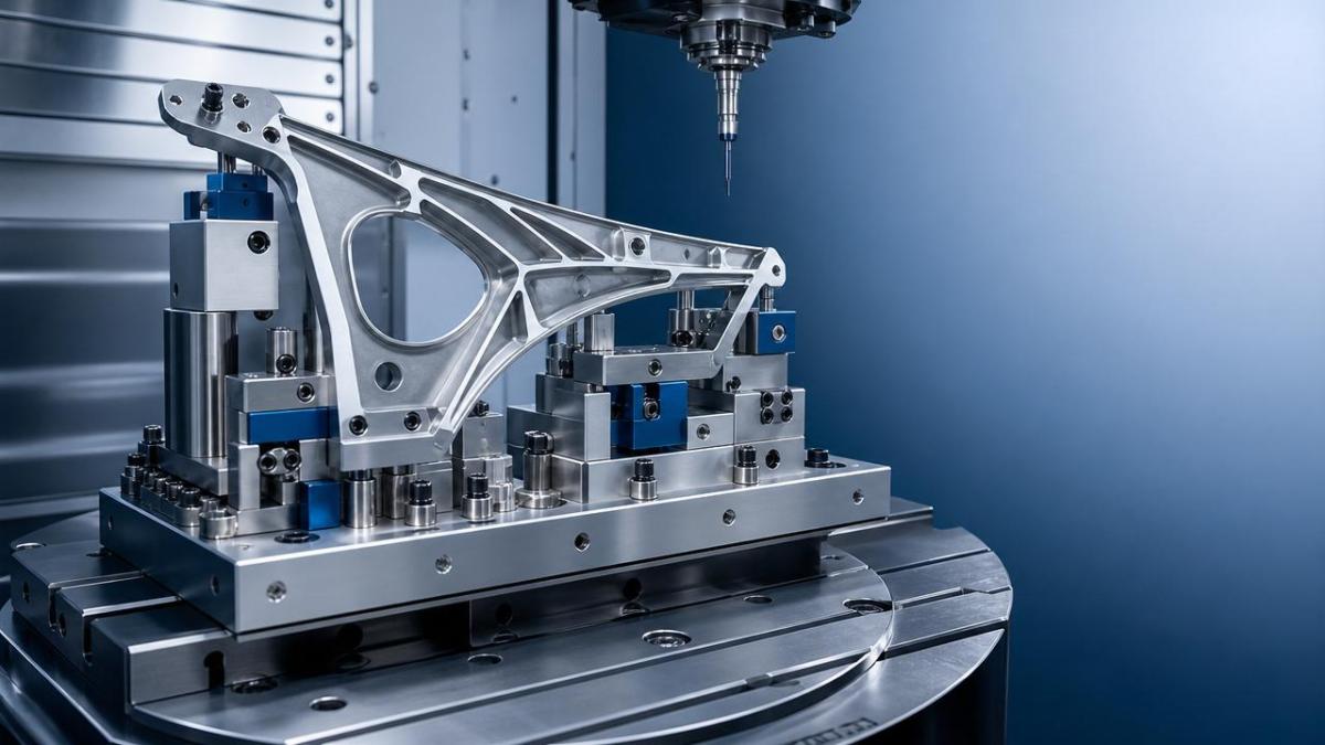
3) Tool access and collision-free machining envelope
Fixtures that secure the part well but block cutting access create longer tools, extra setups, and more vibration risk. Check whether fixture elements interfere with spindle reach, 5-axis articulation, probing cycles, coolant flow, or chip evacuation. The best fixture design protects the part while preserving the shortest, stiffest, and safest tool path possible.
4) Setup repeatability across batches
One successful prototype setup is not enough. Project leaders should verify how repeatability is maintained across operators, shifts, and machine platforms. Ask for documented locating repeatability, standardized loading instructions, error-proofing features, and fixture wear management. In supplier qualification, this is often where hidden variation appears.
5) Inspection compatibility
If the fixture concept cannot support probing, CMM correlation, or in-process verification, nonconformance may not be discovered until final inspection. Confirm whether inspection datums match machining datums, whether reference targets are built into the setup strategy, and whether the part can be measured in a free-state condition when required. For regulated aerospace programs, measurement logic should be integrated from the start.
6) Material-specific response
Aluminum, titanium, Inconel, and composite-adjacent assemblies each react differently to machining and fixturing forces. Titanium may hold residual stress that shifts after heavy stock removal. Aluminum monolithic parts may move significantly as pockets open. Heat-resistant alloys can increase cutting loads and thermal sensitivity. Fixturing for precision machining for aerospace components must be material-aware, not generic.
7) Change control and scalability
Programs evolve. Hole patterns change, weight is reduced, or inspection criteria tighten. A fixture with no flexibility can turn minor engineering changes into major lead-time events. Ask whether modular elements, replaceable nests, or adjustable support points are included to reduce future disruption.
A quick evaluation table for supplier and internal reviews
Different aerospace scenarios require different fixturing priorities
Not all aerospace work should be reviewed with the same emphasis. Project managers can improve decision speed by matching fixture priorities to part type and production objective.
Thin-wall structural parts
Focus on deformation control, residual stress release, and free-state measurement. Ask about staged stock removal, intermediate stress relief where applicable, and support strategies that follow the part as rigidity changes through the process.
Complex 5-axis housings and brackets
Prioritize tool access, reorientation accuracy, and collision avoidance. For precision machining for aerospace components with multiple angled features, the fixture must minimize re-clamping while preserving datum integrity.
Engine and heat-resistant alloy components
Examine thermal behavior, cutting force stability, and fixture durability. Materials such as nickel-based alloys can transfer higher loads into the setup, so contact surfaces, clamp reliability, and anti-vibration design become more critical.
Prototype versus production transition
Prototype fixtures often favor speed and flexibility, while production fixtures must support repeatability, documentation, and operator consistency. A common mistake is keeping a prototype-style fixture too long and then discovering it cannot sustain production capability targets.
Commonly missed issues that create cost and schedule problems
- Assuming machine accuracy alone will protect tolerance. Machine capability matters, but poor fixturing can still defeat an excellent platform.
- Using clamp locations chosen for convenience rather than load path control. This often causes hidden distortion.
- Ignoring part behavior after unclamping. Final geometry must be verified in the relevant state, not only in the compressed state.
- Separating machining planning from inspection planning. When these functions are disconnected, datum conflicts appear late.
- Underestimating fixture wear and maintenance. Repeatability degrades gradually, which makes root-cause analysis harder.
- Failing to document setup instructions clearly enough for shift-to-shift consistency or multisite production transfer.
Practical execution steps for better precision machining for aerospace components
If your organization is planning a new aerospace program, qualifying a supplier, or improving an existing cell, use this execution sequence:
- Map the print’s functional datums to the proposed fixture datums and identify any mismatch immediately.
- Review the part by stiffness zones, not only by overall dimensions, to predict where clamping and cutting loads will create movement.
- Run a setup review that includes machining, quality, and manufacturing engineering together; do not treat fixturing as a machining-only decision.
- Request repeatability evidence from suppliers, including loading consistency, probing strategy, and historical performance on similar parts.
- Build in an inspection correlation plan early so first article, in-process checks, and final verification use compatible logic.
- Plan for change by asking whether the fixture can absorb revision updates without a full redesign.
This structured review supports the kind of evidence-based engineering that organizations like TechStat Vanguard advocate: strip away vague claims and ask for process truth. In high-value manufacturing, parameters, repeatability, and traceable setup logic are what reduce risk. That is especially true in precision machining for aerospace components, where a fixture design decision can affect qualification time as much as machining speed does.
What to prepare before discussing a fixture strategy with a supplier or internal team
To move from general discussion to an actionable plan, prepare a focused information package. Include the latest drawing revision, critical-to-function features, material condition, stock form, expected production volume, required certifications, first article expectations, known distortion concerns, and preferred inspection workflow. Also define whether the priority is prototype speed, process capability, recurring cost reduction, or long-term production stability. These details help determine the most suitable fixturing approach instead of forcing the supplier to make assumptions.
If you need to confirm the best path forward, start by asking five direct questions: Which datums will the fixture control? How will deformation be prevented and verified? How many setups are required? How is repeatability measured over time? And how will the setup support inspection and future engineering changes? Clear answers to these questions will do more for aerospace program success than any generic promise of “high quality” ever can.
Search News
Hot Articles
- Carbon Fiber StructuresHow to Specify Aerospace Carbon Fiber Assemblies for Lightweight, Load-Bearing PartsJul 11, 2026
- Machine VisionXiaomi, Alibaba DAMO Academy Drive Open-Source Robotics Model Ecosystem, Lowering Algorithm Development Barriers for Overseas SMEs Adopting Chinese Robotics SolutionsMar 30, 2026
- Cobots & ArmsShanxi 'AI+' Conference Showcases Embodied Intelligence with Multinational Buyer Engagement: Key Industry ImplicationsMar 30, 2026
Popular Tags
Recommended News
 Jul 11, 2026How to Specify Aerospace Carbon Fiber Assemblies for Lightweight, Load-Bearing PartsAerospace carbon fiber assemblies: learn how to specify laminate design, load data, joining methods, and inspection controls for lighter, reliable load-bearing aerospace parts.Elena Rostova (UAV Systems Researcher)
 Mar 30, 2026Xiaomi, Alibaba DAMO Academy Drive Open-Source Robotics Model Ecosystem, Lowering Algorithm Development Barriers for Overseas SMEs Adopting Chinese Robotics SolutionsXiaomi & Alibaba DAMO Academy's open-source robotics models lower algorithm barriers for global SMEs. Boost efficiency in manufacturing, logistics & smart retail with ROS 2 compatible solutions.TSV Data Lab
 Mar 30, 2026Shanxi 'AI+' Conference Showcases Embodied Intelligence with Multinational Buyer Engagement: Key Industry ImplicationsShanxi 'AI+' Conference highlights embodied intelligence with Tesla, Ubtech & Jiantao showcasing multimodal robotics. 40+ global buyers validated tech on-site, creating new B2B channels for industrial automation & AI solutions.Chen Wei (Automation Lead Engineer)
 Mar 30, 2026Zhongguancun Unveils 6G Integrated Sensing-Computing-Intelligence Platform to Empower Embodied Robots for Global Industrial ApplicationsZhongguancun's new 6G platform revolutionizes industrial robotics with <10ms latency, empowering global automotive, logistics & port automation. Discover how this tech boosts China's smart manufacturing exports.TSV Data Lab
 Mar 30, 2026Mech-Mind Tianjin Embodied Intelligence R&D and Production Base Goes Live, Cutting Delivery Time by 20%–30% for Global Customized AMR+Vision SolutionsMech-Mind's Tianjin AMR+Vision production base cuts delivery time by 20%-30% for欧美 & Latin American markets. Discover how this PLd-certified facility accelerates customized robotics solutions for smart manufacturing and logistics.Chen Wei (Automation Lead Engineer)
 Mar 30, 2026Boao Forum Reveals 'Co-evolution of Big and Small Brains' Trend in Humanoid Robots, China's Embodied Intelligence Accelerates Adaptation to Overseas Manufacturing Service ScenariosDiscover how China's humanoid robots, featuring 'Co-evolution of Big and Small Brains,' are revolutionizing global manufacturing. Learn about Embodied Tian Gong 3.0's ISO compliance and overseas deployment at Boao Forum 2026.Chen Wei (Automation Lead Engineer)
 Mar 30, 2026China Railway Industrial Secures Patent for Embodied Robotics in Material Handling, Boosting High-Precision Delivery Capabilities for Overseas Infrastructure and Manufacturing ProjectsChina Railway Industrial's new patent for embodied robotics in material handling boosts high-precision delivery for global infrastructure & manufacturing. Discover how this innovation enhances logistics accuracy in automotive, rail transit & EPC projects.Chen Wei (Automation Lead Engineer)
 Sep 28, 2026Spindle Runout Measurement in Germany: DIN Standards, Methods, and Acceptance LimitsSpindle runout measurement Germany: explore DIN standards, proven methods, acceptance limits, and audit-ready practices for reliable machining quality.Dr. Marcus Vance
 Sep 27, 2026How to Select Wall-Mount Edge Devices for Space-Constrained Factory NetworksWall mount edge devices for space-constrained factories: evaluate workload, thermal design, power resilience, cable access, and network reliability for smarter deployments.TSV Data Lab
 Sep 26, 2026Machining Tolerance Analysis: How to Set Limits That Meet Function and Cost TargetsMachining tolerance analysis: learn how to set functional limits, control tolerance stacks, reduce inspection risk, and balance precision with production cost.Dr. Marcus Vance
 Sep 25, 2026How to Evaluate an Industrial Infrastructure Data Platform for Multi-Site OperationsIndustrial infrastructure data platform evaluation guide for multi-site operations: compare data quality, edge resilience, interoperability, governance, and scalable proof-of-value criteria.Victor Lin (Chief Software Architect)
 Sep 24, 2026How to Select Machine Vision Optics for Accurate Inspection at Different Working DistancesMachine vision optics selection guide for accurate inspection at every working distance. Compare FOV, pixel scale, DOF, distortion, lighting, and telecentric options.TSV Data Lab
 Sep 23, 2026How to Evaluate a Machine Vision System Integrator for High-Speed Inspection LinesChoose a machine vision system integrator with proven expertise in high-speed inspection, reliable reject timing, robust optics, and measurable acceptance criteria.TSV Data Lab
 Sep 28, 2026When is a SCADA API the right choice for connecting plant systems?SCADA API guide: learn when governed plant data integration improves traceability, security, and scalability—without compromising real-time control.Victor Lin (Chief Software Architect)
 Sep 27, 2026How SCADA data integration improves traceability across production linesSCADA data integration connects production-line data to improve traceability, accelerate quality investigations, and strengthen safety decisions.Victor Lin (Chief Software Architect)
 Sep 26, 2026What to define before starting SCADA integration planningSCADA integration planning starts with clear scope, control boundaries, data models, cybersecurity, and testing. Discover the definitions that reduce risk and costly rework.Victor Lin (Chief Software Architect)
 Sep 25, 2026How a smart factory with Industrial IoT reduces production blind spotsDiscover how a smart factory with Industrial IoT turns real-time machine, quality, and workflow data into actionable insights that reduce production blind spots and delivery risks.Victor Lin (Chief Software Architect)
 Sep 24, 2026When does Industrial IoT make smart manufacturing easier to scale?Smart manufacturing Industrial IoT scales when trusted data, interoperable systems, and secure workflows turn connected assets into measurable gains.TSV Data Lab
 Sep 23, 2026What drives ultra-precision machining cost at 1-micron tolerance?Ultra precision machining cost per part at 1 micron tolerance depends on process, material, metrology, and yield. Learn how to compare quotes confidently.Dr. Marcus Vance
 Sep 22, 2026Drone Engine-T550CC Applications: Build the UAV Power System Around the MissionAn application guide for Drone Engine-T550CC integration, covering payload planning, airframe matching, cooling, fuel, vibration, test procedures, documentation, and service preparation.Elena Rostova (UAV Systems Researcher)
 Sep 22, 2026How to Evaluate Industrial Edge Computing Vendors for Factory DeploymentIndustrial edge computing vendor evaluation guide for factories: compare latency, protocol fit, reliability, security, and lifecycle support before deployment.TSV Data Lab
 Sep 21, 2026Drone Payload Integration: Matching Power, Data, and Center of Gravity for Reliable FlightsDrone payload integration made practical: balance power, data, center of gravity, and endurance to build safer, more reliable mission-ready flights.Elena Rostova (UAV Systems Researcher)
 Sep 20, 2026Autonomous Navigation Pricing: Cost Drivers and Budget Benchmarks for AMR ProjectsAutonomous navigation price explained: compare AMR cost drivers, software, sensors, integration, safety, and lifecycle budgets to build a scalable project plan.Chen Wei (Automation Lead Engineer)
 Sep 19, 2026How to Scope Automation Integration Services for Multi-System Factory ProjectsAutomation integration services: learn how to scope multi-system factory projects with clear workflows, interface contracts, safety boundaries, and acceptance criteria.Victor Lin (Chief Software Architect)























