
Inconel machining for turbine blades without rapid tool wear
Publication Date
author
Inconel machining for turbine blades demands more than generic cutting advice—it requires controlled heat, stable toolpaths, and verified process data to prevent rapid tool wear. For machine operators and shop-floor teams, understanding how feed rates, tool geometry, coolant strategy, and rigidity interact is essential to achieving consistent blade quality, tighter tolerances, and longer tool life in aerospace-grade production.
In practical aerospace machining, turbine blades made from nickel-based superalloys place unusual stress on machines, holders, inserts, and process discipline. Operators are not simply removing metal; they are managing a narrow thermal window where excessive cutting heat, vibration, or chip recutting can quickly damage tools and compromise profile accuracy. For teams working under AS9100-oriented quality expectations, even a small shift in edge wear can affect surface integrity, root geometry, and downstream inspection results.
At TechStat Vanguard, the focus is not promotional language but measurable machining behavior. When discussing inconel machining for turbine blades, the most useful guidance is process-specific: spindle stability, radial engagement, coolant delivery pressure, insert edge preparation, and how many minutes of stable cutting can be achieved before wear becomes non-linear. That is the information operators, process engineers, and production planners can actually use on the shop floor.
Why Inconel Creates Rapid Tool Wear in Turbine Blade Production
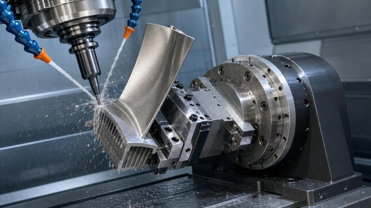
Inconel is difficult to machine because it combines high hot strength, low thermal conductivity, and strong work-hardening behavior. During blade milling, a large share of the cutting heat remains near the cutting edge rather than dissipating into the chip or workpiece. In many shops, the practical result is flank wear, notch wear, built-up edge, or sudden chipping after only 8 to 20 minutes of unstable cutting, especially during roughing of airfoil sections or root features.
For operators, the key issue is not simply that Inconel is “hard.” The larger problem is that process errors compound quickly. A feed per tooth that is too low may cause rubbing and heat concentration. A radial engagement that is too high may spike spindle load. A weak holder or long overhang may introduce vibration that turns gradual wear into catastrophic edge failure within 1 or 2 passes.
Common wear mechanisms seen on the machine floor
Most tool damage in inconel machining for turbine blades falls into 4 recurring categories. Each one points to a different corrective action, so operators should diagnose wear visually rather than replacing tools without root-cause review.
- Flank wear: often linked to extended cutting time, excessive temperature, or insufficient edge strength.
- Notch wear at the depth-of-cut line: common when scale, interrupted engagement, or work-hardening is present.
- Chipping: usually associated with vibration, poor clamping, or aggressive entry/exit strategy.
- Built-up edge and smearing: often caused by low effective chip load, unstable coolant access, or edge geometry mismatch.
Where turbine blade geometry increases the risk
Blade machining is rarely uniform. Thin walls, twisted airfoil surfaces, root slots, and platform transitions create changing contact conditions. A process that is stable at 12% radial engagement on one section may become unstable at the leading edge where wall stiffness drops. In 5-axis paths, even a small orientation change can affect effective cutting diameter, chip thinning, and coolant reach.
This is why generic speed-and-feed charts are rarely enough. Operators need setup-specific values validated by test cuts, spindle load trends, surface finish checks, and tool wear progression over at least 3 stages: initial cut, mid-life stability, and end-of-life behavior.
The table below summarizes the most common process triggers behind fast wear during inconel machining for turbine blades and the shop-floor symptoms that appear first.
The main conclusion is straightforward: rapid wear usually comes from a combination of heat, instability, and geometry-driven inconsistency rather than a single wrong speed value. Operators who monitor sound, chip color, spindle load variation, and wear pattern after every cycle can often extend tool life by 15% to 30% without changing the machine or the material batch.
Process Parameters That Improve Tool Life Without Sacrificing Blade Accuracy
Stable inconel machining for turbine blades starts with balancing tool life against profile control. In many aerospace cells, chasing maximum metal removal rate too early leads to more insert changes, more offsets, and higher risk of scrap. A better approach is to build a repeatable process window with controlled engagement, measured wear checkpoints, and machine-specific parameter tuning.
Feed, speed, and engagement strategy
For nickel-based superalloys, productive roughing often depends more on engagement control than on absolute spindle speed. Many shops begin with moderate cutting speeds, then refine feed per tooth based on insert behavior and machine rigidity. On a stable 5-axis setup, radial engagement is often kept in a lower band, such as 8% to 15% of cutter diameter during contouring, while axial depth is used more efficiently to spread heat and reduce recutting.
Operators should also be careful with dwell, sharp corners, and abrupt changes in cutter direction. Toolpaths that maintain constant engagement can reduce thermal shock and edge breakdown. Even a 0.2 to 0.4 second pause in the cut may raise local heat enough to shorten effective tool life, especially on finishing tools with smaller edge radii.
Operator checkpoints during parameter adjustment
- Check spindle load trend over the first 3 parts, not only the peak value.
- Inspect edge wear after a fixed cutting interval, such as every 10 to 15 minutes.
- Review chip evacuation in deep or curved zones where recutting is likely.
- Confirm that tool offsets are not drifting as wear approaches the end-of-life zone.
Tool geometry, substrate, and holder selection
Not every carbide tool marketed for superalloys performs the same way on turbine blade features. Edge preparation, flute count, helix design, coating stability, and core strength all matter. For roughing, a stronger edge with controlled hone may resist chipping better. For finishing of thin airfoil sections, lower cutting forces and better evacuation may matter more than maximum edge strength.
Holder rigidity is equally important. Hydraulic or shrink-fit systems are often preferred when runout control and balance matter, especially at higher spindle speeds. A runout difference of more than a few microns can unevenly load the cutting edges, causing one flute to fail early while the others appear underused. On turbine blades, that imbalance can show up as inconsistent finish along the pressure side or suction side profile.
The following table outlines practical parameter and tooling priorities that operators can use when optimizing inconel machining for turbine blades across roughing, semi-finishing, and finishing steps.
This comparison shows that tool life improvement does not come from one universal setting. The right control point changes by stage. Roughing benefits from heat discipline, semi-finishing depends on stiffness, and finishing requires highly predictable edge behavior. When operators align controls to the actual blade feature, tool wear becomes more manageable and part consistency improves.
Coolant Delivery, Machine Rigidity, and Toolpath Discipline
Cooling strategy is often the difference between acceptable wear and expensive instability. Inconel retains heat at the interface, so coolant must reach the active cutting zone consistently. Flood coolant can work in some open-access operations, but complex blade surfaces often benefit from directed high-pressure delivery where chips tend to pack or re-enter the cut. If coolant only hits the tool shank or misses the engagement point during 5-axis motion, wear acceleration is almost guaranteed.
What operators should verify on every setup
- Coolant nozzles aligned to the actual engagement zone, not the static tool position.
- Fixture contact secure enough to prevent micro-movement on thin or tall blade blanks.
- Holder, spindle, and extension stack kept as short as possible.
- Toolpath simulation checked for sudden angle changes, air cuts, and re-entry points.
- Chip evacuation reviewed after the first part and again after thermal stabilization.
Rigidity matters more than headline machine power
A high-horsepower machine alone does not guarantee success in inconel machining for turbine blades. If the spindle-holder-tool system lacks rigidity, usable cutting parameters must be reduced. In many production cells, a stable 18-minute cut with lower vibration is more valuable than a 12-minute aggressive cycle that forces tool changes every part. Tool life, offset stability, and scrap prevention usually outweigh small cycle-time gains.
Machine warm-up and thermal consistency also deserve attention. On close-tolerance blade work, thermal drift over the first 30 to 60 minutes of operation can influence both dimensions and wear behavior. A disciplined warm-up sequence and repeatable startup routine help reduce early-process variation, particularly when the workcell switches between roughing and finishing programs.
Frequent shop-floor mistakes
Three mistakes appear repeatedly. First, reducing feed too much in response to wear often makes rubbing worse. Second, increasing coolant volume without improving nozzle direction may add little value. Third, treating all blade areas with one toolpath strategy ignores local stiffness and geometry changes. Corrective action should be feature-based, not only parameter-based.
Inspection, Process Control, and Procurement Considerations for Consistent Results
For users and operators, machining success is only part of the story. Reliable inconel machining for turbine blades also depends on inspection discipline, tool consumption tracking, and supplier transparency. If a shop cannot document wear progression, offset changes, coolant method, and batch-level consistency, it becomes difficult for procurement teams or production managers to compare machining capability across vendors or workcells.
What should be recorded during production
A practical control plan should capture at least 6 data points: tool number, cutting time per edge, wear type, offset adjustment count, coolant condition, and dimensional check frequency. For aerospace-grade parts, many teams also log part sequence, machine ID, fixture status, and whether any abnormal vibration or chip packing occurred during the cycle. This information helps identify whether wear is gradual, setup-related, or caused by toolpath instability.
Evaluation criteria when selecting a machining partner or internal process route
Whether the decision is internal or external, buyers and technical leads need criteria beyond quoted lead time. The table below can be used as a practical screening framework when reviewing turbine blade machining capability.
For procurement and operations teams, the critical takeaway is that capability should be judged by repeatability and process visibility. A vendor or internal cell that can explain tool life in minutes, wear mode by feature, and inspection frequency by batch is generally less risky than one offering only a fast quotation and broad quality claims.
FAQ from operators and production teams
Should feed always be reduced when wear increases?
Not always. If wear is caused by rubbing, reducing feed may make heat concentration worse. First check chip formation, engagement, and runout before lowering feed.
Is higher coolant pressure always better?
No. Pressure helps only if coolant actually reaches the cut. In blade machining, nozzle position and access through the full toolpath can be as important as pressure level.
How often should tool wear be checked?
During process development, checks every 1 part or every 10 to 15 minutes of actual cutting are common. Once stable behavior is confirmed, the interval can be adjusted based on risk and feature sensitivity.
Successful inconel machining for turbine blades depends on disciplined control of heat, engagement, rigidity, and verification data. Operators who understand wear modes, maintain stable toolpaths, and document real cutting behavior can protect both tool life and blade quality. For aerospace manufacturers, suppliers, and machining teams that need process benchmarking grounded in measurable engineering reality, TechStat Vanguard provides the data-first perspective required to reduce trial-and-error and improve supplier confidence. Contact us to discuss machining benchmarks, process validation priorities, or a tailored evaluation framework for your turbine blade production environment.
Search News
Hot Articles
- Carbon Fiber StructuresHow to Specify Aerospace Carbon Fiber Assemblies for Lightweight, Load-Bearing PartsJul 11, 2026
- Machine VisionXiaomi, Alibaba DAMO Academy Drive Open-Source Robotics Model Ecosystem, Lowering Algorithm Development Barriers for Overseas SMEs Adopting Chinese Robotics SolutionsMar 30, 2026
- Cobots & ArmsShanxi 'AI+' Conference Showcases Embodied Intelligence with Multinational Buyer Engagement: Key Industry ImplicationsMar 30, 2026
Popular Tags
Recommended News
 Jul 11, 2026How to Specify Aerospace Carbon Fiber Assemblies for Lightweight, Load-Bearing PartsAerospace carbon fiber assemblies: learn how to specify laminate design, load data, joining methods, and inspection controls for lighter, reliable load-bearing aerospace parts.Elena Rostova (UAV Systems Researcher)
 Mar 30, 2026Xiaomi, Alibaba DAMO Academy Drive Open-Source Robotics Model Ecosystem, Lowering Algorithm Development Barriers for Overseas SMEs Adopting Chinese Robotics SolutionsXiaomi & Alibaba DAMO Academy's open-source robotics models lower algorithm barriers for global SMEs. Boost efficiency in manufacturing, logistics & smart retail with ROS 2 compatible solutions.TSV Data Lab
 Mar 30, 2026Shanxi 'AI+' Conference Showcases Embodied Intelligence with Multinational Buyer Engagement: Key Industry ImplicationsShanxi 'AI+' Conference highlights embodied intelligence with Tesla, Ubtech & Jiantao showcasing multimodal robotics. 40+ global buyers validated tech on-site, creating new B2B channels for industrial automation & AI solutions.Chen Wei (Automation Lead Engineer)
 Mar 30, 2026Zhongguancun Unveils 6G Integrated Sensing-Computing-Intelligence Platform to Empower Embodied Robots for Global Industrial ApplicationsZhongguancun's new 6G platform revolutionizes industrial robotics with <10ms latency, empowering global automotive, logistics & port automation. Discover how this tech boosts China's smart manufacturing exports.TSV Data Lab
 Mar 30, 2026Mech-Mind Tianjin Embodied Intelligence R&D and Production Base Goes Live, Cutting Delivery Time by 20%–30% for Global Customized AMR+Vision SolutionsMech-Mind's Tianjin AMR+Vision production base cuts delivery time by 20%-30% for欧美 & Latin American markets. Discover how this PLd-certified facility accelerates customized robotics solutions for smart manufacturing and logistics.Chen Wei (Automation Lead Engineer)
 Mar 30, 2026Boao Forum Reveals 'Co-evolution of Big and Small Brains' Trend in Humanoid Robots, China's Embodied Intelligence Accelerates Adaptation to Overseas Manufacturing Service ScenariosDiscover how China's humanoid robots, featuring 'Co-evolution of Big and Small Brains,' are revolutionizing global manufacturing. Learn about Embodied Tian Gong 3.0's ISO compliance and overseas deployment at Boao Forum 2026.Chen Wei (Automation Lead Engineer)
 Mar 30, 2026China Railway Industrial Secures Patent for Embodied Robotics in Material Handling, Boosting High-Precision Delivery Capabilities for Overseas Infrastructure and Manufacturing ProjectsChina Railway Industrial's new patent for embodied robotics in material handling boosts high-precision delivery for global infrastructure & manufacturing. Discover how this innovation enhances logistics accuracy in automotive, rail transit & EPC projects.Chen Wei (Automation Lead Engineer)
 Sep 28, 2026Spindle Runout Measurement in Germany: DIN Standards, Methods, and Acceptance LimitsSpindle runout measurement Germany: explore DIN standards, proven methods, acceptance limits, and audit-ready practices for reliable machining quality.Dr. Marcus Vance
 Sep 27, 2026How to Select Wall-Mount Edge Devices for Space-Constrained Factory NetworksWall mount edge devices for space-constrained factories: evaluate workload, thermal design, power resilience, cable access, and network reliability for smarter deployments.TSV Data Lab
 Sep 26, 2026Machining Tolerance Analysis: How to Set Limits That Meet Function and Cost TargetsMachining tolerance analysis: learn how to set functional limits, control tolerance stacks, reduce inspection risk, and balance precision with production cost.Dr. Marcus Vance
 Sep 25, 2026How to Evaluate an Industrial Infrastructure Data Platform for Multi-Site OperationsIndustrial infrastructure data platform evaluation guide for multi-site operations: compare data quality, edge resilience, interoperability, governance, and scalable proof-of-value criteria.Victor Lin (Chief Software Architect)
 Sep 24, 2026How to Select Machine Vision Optics for Accurate Inspection at Different Working DistancesMachine vision optics selection guide for accurate inspection at every working distance. Compare FOV, pixel scale, DOF, distortion, lighting, and telecentric options.TSV Data Lab
 Sep 23, 2026How to Evaluate a Machine Vision System Integrator for High-Speed Inspection LinesChoose a machine vision system integrator with proven expertise in high-speed inspection, reliable reject timing, robust optics, and measurable acceptance criteria.TSV Data Lab
 Sep 28, 2026When is a SCADA API the right choice for connecting plant systems?SCADA API guide: learn when governed plant data integration improves traceability, security, and scalability—without compromising real-time control.Victor Lin (Chief Software Architect)
 Sep 27, 2026How SCADA data integration improves traceability across production linesSCADA data integration connects production-line data to improve traceability, accelerate quality investigations, and strengthen safety decisions.Victor Lin (Chief Software Architect)
 Sep 26, 2026What to define before starting SCADA integration planningSCADA integration planning starts with clear scope, control boundaries, data models, cybersecurity, and testing. Discover the definitions that reduce risk and costly rework.Victor Lin (Chief Software Architect)
 Sep 25, 2026How a smart factory with Industrial IoT reduces production blind spotsDiscover how a smart factory with Industrial IoT turns real-time machine, quality, and workflow data into actionable insights that reduce production blind spots and delivery risks.Victor Lin (Chief Software Architect)
 Sep 24, 2026When does Industrial IoT make smart manufacturing easier to scale?Smart manufacturing Industrial IoT scales when trusted data, interoperable systems, and secure workflows turn connected assets into measurable gains.TSV Data Lab
 Sep 23, 2026What drives ultra-precision machining cost at 1-micron tolerance?Ultra precision machining cost per part at 1 micron tolerance depends on process, material, metrology, and yield. Learn how to compare quotes confidently.Dr. Marcus Vance
 Sep 22, 2026Drone Engine-T550CC Applications: Build the UAV Power System Around the MissionAn application guide for Drone Engine-T550CC integration, covering payload planning, airframe matching, cooling, fuel, vibration, test procedures, documentation, and service preparation.Elena Rostova (UAV Systems Researcher)
 Sep 22, 2026How to Evaluate Industrial Edge Computing Vendors for Factory DeploymentIndustrial edge computing vendor evaluation guide for factories: compare latency, protocol fit, reliability, security, and lifecycle support before deployment.TSV Data Lab
 Sep 21, 2026Drone Payload Integration: Matching Power, Data, and Center of Gravity for Reliable FlightsDrone payload integration made practical: balance power, data, center of gravity, and endurance to build safer, more reliable mission-ready flights.Elena Rostova (UAV Systems Researcher)
 Sep 20, 2026Autonomous Navigation Pricing: Cost Drivers and Budget Benchmarks for AMR ProjectsAutonomous navigation price explained: compare AMR cost drivers, software, sensors, integration, safety, and lifecycle budgets to build a scalable project plan.Chen Wei (Automation Lead Engineer)
 Sep 19, 2026How to Scope Automation Integration Services for Multi-System Factory ProjectsAutomation integration services: learn how to scope multi-system factory projects with clear workflows, interface contracts, safety boundaries, and acceptance criteria.Victor Lin (Chief Software Architect)























