CNC Spindle Runout Measurement Why One Reading Is Never Enough
Publication Date
author
In precision machining, cnc spindle runout measurement is not a box to tick but a decision-critical process. A single reading can hide thermal drift, tool interface variation, and bearing behavior that directly affect custom machining for robotics joints, cnc machining for drone structural parts, and precision grinding for aerospace bearings. This article explains why multiple measurements reveal the engineering truth procurement teams, operators, and decision-makers actually need.
Why a single cnc spindle runout measurement creates false confidence
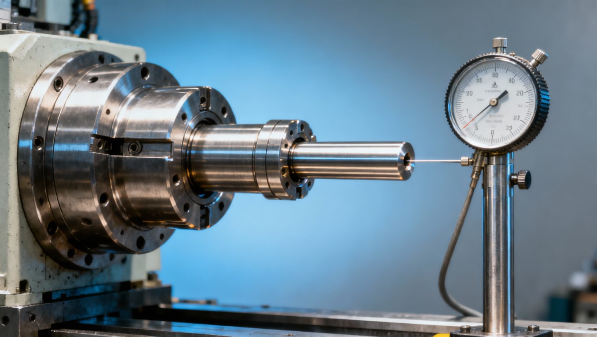
Many shops still record one cnc spindle runout measurement at one spindle position, one temperature state, and one toolholding setup. That approach is fast, but it is not reliable enough for supplier qualification, process validation, or root-cause analysis. In real production, spindle behavior changes across cold start, thermal stabilization, tool change cycles, and different taper contact conditions.
For operators, one reading may look acceptable while surface finish, bore geometry, or tool life keeps drifting during a 2-hour to 6-hour production window. For procurement teams, a supplier that reports only one value without measurement context gives incomplete evidence. For engineering managers, that missing context can turn a nominally acceptable spindle into a recurring quality problem.
This is exactly where TechStat Vanguard (TSV) applies a data-first lens. Rather than accepting broad claims, TSV focuses on measurable states, traceable conditions, and tolerance-linked interpretation. In precision machining benchmarks, parameters matter only when the measurement method is repeatable, the boundary conditions are stated, and the data series is wide enough to show variation.
A practical spindle runout assessment usually needs at least 3 dimensions of validation: location, condition, and repeatability. Location means where the indicator is placed, such as taper, test bar near gauge line, or tool tip. Condition means cold, warmed up, or post-cycle. Repeatability means the result across multiple spindle orientations, tool changes, or time intervals such as 15-minute, 30-minute, and 60-minute checkpoints.
What one reading often fails to capture
- Thermal growth after spindle running at moderate or high speed for 20–40 minutes.
- Toolholder seating variation after 3–5 clamp and unclamp cycles.
- Bearing response that appears only at certain angular positions or speed bands.
- Contamination, taper wear, pull-stud mismatch, or gauge bar quality issues.
If the spindle supports tight-tolerance parts for robotics, UAV frames, medical fixtures, or aerospace bearing seats, these hidden variables are not minor details. They directly influence circularity, positional accuracy, vibration, and scrap exposure. One isolated number can support a marketing narrative, but it cannot support an engineering decision.
How to measure spindle runout the right way in multi-condition testing
A useful cnc spindle runout measurement program should mirror how the spindle is actually used. That means measuring more than once and measuring at more than one point. In many practical evaluations, teams use a staged process: taper inspection, test bar inspection, warm-up cycle, repeated clamping, and then speed-related verification. This creates a data sequence instead of a single snapshot.
The first checkpoint is often the spindle taper or interface itself. If taper cleanliness, contact condition, or retention force is unstable, tool tip readings will become hard to interpret. The second checkpoint is a qualified test bar or mandrel measured near the spindle nose and again farther away, because short-distance readings can look fine even when angular error amplifies farther from the gauge line.
The third checkpoint is time. A spindle that reads one way at startup and another way after 30 minutes is telling you something important about thermal state or bearing condition. The fourth checkpoint is repetition. If the operator mounts the same holder 5 times and gets 5 noticeably different values, the interface system, not only the spindle core, must be investigated.
For procurement and supplier audits, the measurement protocol should be documented in the RFQ or technical review process. Without a defined method, two suppliers can report the same nominal runout figure while using very different distances, indicator setups, spindle temperatures, and clamp cycles. That makes side-by-side comparison weak and risky.
Recommended measurement checkpoints for better comparability
The table below summarizes a practical framework for cnc spindle runout measurement that is more useful for engineering review, machine acceptance, and supplier benchmarking than a one-point reading.
This structure does not pretend to replace every OEM procedure, but it makes comparisons far more meaningful. It also aligns with TSV’s core view: decisions in hard-tech procurement should be driven by traceable parameters and test conditions, not by generic statements about precision.
A practical 4-step shop floor sequence
- Clean and inspect taper, holder, and test bar; confirm indicator setup and contact point.
- Measure baseline at cold condition, then repeat after a controlled warm-up period.
- Repeat the same measurement after 3–5 clamp cycles to assess interface repeatability.
- Compare readings at short and extended distances to distinguish radial and angular effects.
When this sequence is followed consistently, it becomes easier to identify whether the risk sits in the spindle, the holder system, the thermal condition, or the measurement method itself. That clarity saves time for operators and reduces dispute during technical-commercial review.
Which applications are most sensitive to hidden runout variation?
Not every production job reacts to spindle runout in the same way. General roughing of low-risk parts may tolerate broader variation than finishing, micro-machining, thin-wall structures, or hard-material grinding. The business risk rises when one machine serves sectors where tolerance stack-up, balance, or fatigue life are critical. That is common in robotics, UAV, sensor assemblies, and aerospace-related subcontracting.
In robotics joints and motion components, hidden runout can affect bearing fits, gear housing alignment, and mating surface accuracy. In drone structural parts, especially lightweight aluminum or composite-compatible fixtures, excess runout can increase chatter, tool wear, and edge inconsistency. In aerospace bearing-related grinding or finish machining, even small deviations may amplify vibration signatures and reduce process confidence.
For decision-makers, the key question is not whether runout exists, but whether the measured variation is relevant to the target process capability. A supplier making general machine parts and a supplier machining high-value flight hardware should not be assessed with the same level of spindle evidence. The measurement burden must fit the application risk.
That is why TSV emphasizes application-linked interpretation. Engineering truth does not come from isolated values. It comes from matching measurement depth to actual use conditions, tolerance sensitivity, and failure consequences over a production cycle of 50 parts, 500 parts, or recurring monthly batches.
Application scenarios and evaluation focus
The following comparison helps information researchers, operators, and buyers judge where multi-point spindle runout verification is most important.
The point is not to over-test every machine. The point is to test with enough depth to match process risk. That balance is especially valuable when a procurement team needs to compare suppliers serving several industries under one sourcing program.
What buyers and technical teams should ask before accepting spindle data
When a supplier submits spindle precision data, the first question should be simple: under what conditions was the cnc spindle runout measurement taken? If the answer does not include measurement location, spindle temperature state, toolholding condition, and repetition count, the number has limited value. A polished report is not the same as a decision-grade report.
For procurement personnel, the goal is not to become metrology specialists. The goal is to avoid weak comparability. A robust request-for-information can ask for 5 basic items: measurement point, test artifact used, warm-up condition, number of repeats, and whether the values represent spindle taper, test bar, or tool tip. Those five items immediately improve supplier transparency.
For operators and production engineers, the concern is actionability. If runout data cannot distinguish between taper contamination, holder inconsistency, spindle bearing degradation, or measurement setup error, then the result will not support corrective action. That often causes unnecessary downtime, replacement of the wrong component, or recurring scrap after maintenance.
For executives and plant managers, the hidden cost is qualification delay. When spindle data is incomplete, incoming machine acceptance, process validation, and supplier approval all take longer. In many projects, a clear measurement plan shortens technical clarification by days or even weeks because fewer rounds of re-testing are needed.
A practical supplier assessment checklist
- Ask whether values were measured at the spindle taper, test bar, and tool tip, not only at one point.
- Confirm whether readings were taken cold and after a defined warm-up interval such as 20–30 minutes.
- Request repeated measurements after 3–5 remount cycles to evaluate interface consistency.
- Check whether the supplier links spindle data to part tolerance, finish requirement, and tool life outcomes.
- Review whether the same method is used across machines, shifts, and acceptance reports.
Common decision errors in sourcing and machine acceptance
One frequent mistake is treating a low single reading as proof of stable spindle performance. Another is comparing numbers from different setups as if they were equivalent. A third is assuming the spindle alone determines runout, while ignoring holder quality, pull-stud condition, contamination, and thermal behavior. These errors can distort both capex decisions and supplier scorecards.
TSV’s benchmarking perspective is designed for exactly this problem. By filtering out vague claims and centering the discussion on test method, repeatability, and tolerance relevance, buyers can compare engineering reality instead of brochure language. That reduces qualification noise and raises confidence in sourcing decisions for advanced manufacturing programs.
FAQ and next-step guidance for better measurement and supplier communication
Search intent around cnc spindle runout measurement usually includes three overlapping needs: understanding the concept, knowing how to verify it properly, and deciding what evidence is enough during supplier selection. The questions below address those needs directly and translate them into practical next steps for real projects.
How many readings are enough for cnc spindle runout measurement?
There is no single universal count, but one reading is rarely enough for precision-critical work. A practical minimum is a small matrix of readings across at least 3 conditions: initial state, post-warm-up state, and repeated clamping state. If the machine supports high-value or tight-tolerance parts, add multiple positions and time checkpoints such as 0, 30, and 60 minutes.
Is tool tip runout more important than taper runout?
Tool tip runout is often closer to process reality because the cut happens there, but taper or interface readings are still essential for diagnosis. If taper readings are stable while tool tip values vary, the issue may sit in the holder, tool assembly, or extension length. Good troubleshooting uses both levels rather than choosing only one.
What should a buyer request in an RFQ or supplier audit?
Request the method, not just the number. Ask for measurement point, test artifact, warm-up condition, repeat count, and the link to target part tolerance. If the supplier serves regulated or high-reliability sectors, also ask how spindle verification is documented during machine acceptance, preventive maintenance, and capability review intervals such as monthly or quarterly checks.
Can a stable runout value guarantee part quality?
No. Stable runout data is necessary, but it does not replace full process control. Tool balance, cutter geometry, fixturing, material behavior, coolant delivery, thermal management, and program strategy also affect outcomes. However, poor or poorly measured runout can undermine all of those controls, which is why measurement quality deserves more attention than it usually gets.
Why choose a data-driven partner for technical benchmarking and sourcing support?
Because advanced manufacturing decisions fail when technical claims are not traceable. TechStat Vanguard focuses on engineering truth through data, helping R&D teams, procurement leaders, and decision-makers evaluate hard-tech capability with clearer parameters, more comparable evidence, and less marketing noise. That matters when tolerances, fatigue limits, or equipment thresholds directly affect cost and risk.
If your team is reviewing spindle capability, supplier qualification, or precision machining benchmarks, contact TSV for support on parameter confirmation, measurement framework design, supplier comparison logic, delivery-cycle discussion, custom evaluation criteria, and technical communication for RFQs or spec sheets. The most useful conversation usually starts with a simple question: what exactly was measured, under which conditions, and how repeatable was it?
Search News
Hot Articles
- Carbon Fiber StructuresHow to Specify Aerospace Carbon Fiber Assemblies for Lightweight, Load-Bearing PartsJul 11, 2026
- Machine VisionXiaomi, Alibaba DAMO Academy Drive Open-Source Robotics Model Ecosystem, Lowering Algorithm Development Barriers for Overseas SMEs Adopting Chinese Robotics SolutionsMar 30, 2026
- Cobots & ArmsShanxi 'AI+' Conference Showcases Embodied Intelligence with Multinational Buyer Engagement: Key Industry ImplicationsMar 30, 2026
Popular Tags
Recommended News
 Jul 11, 2026How to Specify Aerospace Carbon Fiber Assemblies for Lightweight, Load-Bearing PartsAerospace carbon fiber assemblies: learn how to specify laminate design, load data, joining methods, and inspection controls for lighter, reliable load-bearing aerospace parts.Elena Rostova (UAV Systems Researcher)
 Mar 30, 2026Xiaomi, Alibaba DAMO Academy Drive Open-Source Robotics Model Ecosystem, Lowering Algorithm Development Barriers for Overseas SMEs Adopting Chinese Robotics SolutionsXiaomi & Alibaba DAMO Academy's open-source robotics models lower algorithm barriers for global SMEs. Boost efficiency in manufacturing, logistics & smart retail with ROS 2 compatible solutions.TSV Data Lab
 Mar 30, 2026Shanxi 'AI+' Conference Showcases Embodied Intelligence with Multinational Buyer Engagement: Key Industry ImplicationsShanxi 'AI+' Conference highlights embodied intelligence with Tesla, Ubtech & Jiantao showcasing multimodal robotics. 40+ global buyers validated tech on-site, creating new B2B channels for industrial automation & AI solutions.Chen Wei (Automation Lead Engineer)
 Mar 30, 2026Zhongguancun Unveils 6G Integrated Sensing-Computing-Intelligence Platform to Empower Embodied Robots for Global Industrial ApplicationsZhongguancun's new 6G platform revolutionizes industrial robotics with <10ms latency, empowering global automotive, logistics & port automation. Discover how this tech boosts China's smart manufacturing exports.TSV Data Lab
 Mar 30, 2026Mech-Mind Tianjin Embodied Intelligence R&D and Production Base Goes Live, Cutting Delivery Time by 20%–30% for Global Customized AMR+Vision SolutionsMech-Mind's Tianjin AMR+Vision production base cuts delivery time by 20%-30% for欧美 & Latin American markets. Discover how this PLd-certified facility accelerates customized robotics solutions for smart manufacturing and logistics.Chen Wei (Automation Lead Engineer)
 Mar 30, 2026Boao Forum Reveals 'Co-evolution of Big and Small Brains' Trend in Humanoid Robots, China's Embodied Intelligence Accelerates Adaptation to Overseas Manufacturing Service ScenariosDiscover how China's humanoid robots, featuring 'Co-evolution of Big and Small Brains,' are revolutionizing global manufacturing. Learn about Embodied Tian Gong 3.0's ISO compliance and overseas deployment at Boao Forum 2026.Chen Wei (Automation Lead Engineer)
 Mar 30, 2026China Railway Industrial Secures Patent for Embodied Robotics in Material Handling, Boosting High-Precision Delivery Capabilities for Overseas Infrastructure and Manufacturing ProjectsChina Railway Industrial's new patent for embodied robotics in material handling boosts high-precision delivery for global infrastructure & manufacturing. Discover how this innovation enhances logistics accuracy in automotive, rail transit & EPC projects.Chen Wei (Automation Lead Engineer)
 Oct 14, 2026Drone Frame Composites: Carbon Fiber vs. Fiberglass for Weight and StiffnessExplore drone structural materials composites: compare carbon fiber and fiberglass for weight, stiffness, cost, and antenna compatibility. Find the right material for your drone frame.Elena Rostova (UAV Systems Researcher)
 Oct 13, 2026Smart Cameras vs. PC-Based Machine Vision: Which Fits High-Speed Inspection?This industrial product comparison for machine vision weighs smart cameras vs. PC-based systems on latency, throughput, and cost. Discover your best fit for high-speed inspection.TSV Data Lab
 Oct 12, 2026How to Verify RoHS Compliance in Industrial Sensing Systems Before DeploymentRoHS compliant sensing systems: learn how to verify materials, supplier declarations, testing, and configuration controls before industrial deployment.TSV Data Lab
 Oct 11, 2026How Procurement-Oriented Content Taxonomy Improves B2B Buying JourneysProcurement-oriented content taxonomy streamlines B2B buying journeys with clearer evidence, supplier comparisons, risk visibility, and faster approvals.TSV Data Lab
 Oct 10, 2026How to Select a Machine Performance Monitoring Platform for OEE and Downtime ReductionMachine performance monitoring platform selection guide: validate machine states, OEE data, downtime reasons, integrations, and scalability to reduce losses with confidence.TSV Data Lab
 Oct 08, 2026How to Machine Inconel 625 Blades Without Heat Cracks or Edge ChippingInconel 625 blade machining guide: prevent heat cracks, edge chipping, chatter, and work hardening with proven tooling, cooling, fixturing, and inspection strategies.Dr. Marcus Vance
 Oct 07, 2026How to Evaluate an HMI Panel Distributor for Industrial Automation ProjectsHMI panel distributor evaluation guide: verify technical compatibility, traceability, supply reliability, lifecycle support, and total cost for automation projects.Victor Lin (Chief Software Architect)
 Oct 06, 2026Navigation Fault Tolerance Standards for AMRs: What Safety Teams Must VerifyNavigation fault tolerance standards: learn what AMR safety teams must verify, from localization loss and sensor faults to stopping distance, safe restart, and site-specific validation.Chen Wei (Automation Lead Engineer)
 Oct 05, 2026Calculating Edge Computing Total Cost of Ownership Across Distributed SitesEdge computing ownership cost explained: calculate deployment, energy, connectivity, security, remote support, and refresh costs across distributed sites.TSV Data Lab
 Oct 04, 2026CAD/CAM Benchmarking in the GCC: What Manufacturers Should Ask a ConsultantCAD CAM benchmark consultant GCC guide: learn the key questions manufacturers should ask to validate post-processors, workflows, machine performance, and production risk.Victor Lin (Chief Software Architect)
 Oct 03, 2026Selecting Automotive Radar Sensor Modules for ADAS Range, Resolution, and IntegrationAutomotive radar sensor module selection guide for ADAS: compare range, resolution, field of view, latency, and integration to build safer, reliable vehicle systems.TSV Data Lab
 Oct 02, 2026How to Qualify Machined Parts Suppliers for Hard Tech ProgramsHard tech supply chain machined parts demand rigorous supplier qualification. Learn how to assess capability, traceability, quality controls, and delivery resilience.Dr. Marcus Vance
 Oct 01, 2026How to Select an Outdoor Security Radar Sensor for Perimeter Detection?Outdoor security radar sensor selection guide: compare range, accuracy, false-alarm control, integration, and field testing for reliable perimeter detection.TSV Data Lab
 Sep 30, 2026How to Evaluate Solid-State LiDAR Hardware for Outdoor Autonomous VehiclesSolid state LiDAR hardware evaluation guide for outdoor autonomous vehicles—compare range, point-cloud quality, environmental resilience, integration, and safety.TSV Data Lab
 Sep 29, 2026ISO 9283 Repeatability: How to Evaluate Cobot Positioning PerformanceISO 9283 cobot repeatability explained: learn how payload, reach, approach direction, and test conditions affect positioning performance and cell capability.Chen Wei (Automation Lead Engineer)
 Oct 14, 2026How tight can micro machining aerospace tolerances be in production?Micro machining aerospace tolerances can reach low-micron levels in production. Learn what controls repeatability, inspection confidence, and flight-critical quality.Dr. Marcus Vance
 Oct 13, 2026How to keep an industrial robotic integration project on scheduleIndustrial robotic integration project management: keep automation on schedule with proven controls for interfaces, suppliers, FAT, commissioning, and change risk.Victor Lin (Chief Software Architect)