5 Axis CNC Machining CMM Inspection: What to Measure, Probe Strategy, and Common Errors
Publication Date
author
5 Axis CNC Machining CMM Inspection: What to Measure, Probe Strategy, and Common Errors
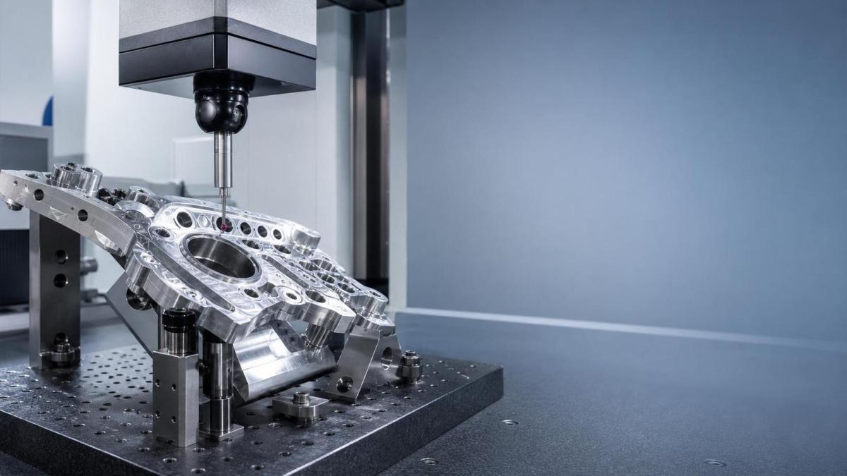
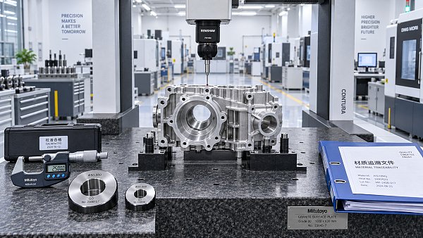
In 5 axis CNC machining CMM inspection, accurate results depend on measuring the right features, selecting a reliable probe strategy, and avoiding hidden setup or alignment errors.
When a part looks good on the machine but fails on the CMM, the issue is often not machining alone.
It may come from a weak inspection plan, poor datum use, or a probe path that misses the real geometry.
That matters even more in aerospace, robotics, sensors, and medical work, where tight tolerances drive fit, motion, and traceability.
At TechStat Vanguard, the practical rule is simple: parameters do not lie, and inspection must prove them clearly.
This guide focuses on 5 axis CNC machining CMM inspection from the shop-floor view, with direct steps that improve confidence and reduce rework.
What to Measure First in 5 Axis CNC Machining CMM Inspection
The first mistake is measuring everything with equal priority.
In real production, some features control assembly, function, and process stability more than others.
For reliable 5 axis CNC machining CMM inspection, start with features tied to datums, location, and critical form.
Priority features usually include
- Primary, secondary, and tertiary datum surfaces
- True position of holes, slots, and patterns
- Profile of complex 3D surfaces
- Perpendicularity, flatness, and parallelism
- Bores, bearing seats, and sealing surfaces
- Wall thickness in thin or weight-sensitive parts
- Blend radii and edge transitions on multi-axis toolpaths
This order keeps the inspection aligned with function, not just print quantity.
For example, a turbine bracket may pass size checks yet fail because the hole pattern drifts from the datum frame.
A housing may hold bore diameter but still create assembly stress if the bore axis tilts slightly.
That is why good 5 axis CNC machining CMM inspection follows the drawing intent and the part function together.
How to Choose the Right Probe Strategy
Probe strategy is where many inspection results become either trustworthy or misleading.
A fast cycle is helpful, but speed has little value if the data misses the actual surface behavior.
In 5 axis CNC machining CMM inspection, probe selection should follow geometry, access, material condition, and tolerance risk.
Use touch-trigger probing when
- Features are simple and discrete
- Hole centers and planes are the main targets
- Cycle time must stay controlled
- Surface finish is stable and repeatable
Use scanning when
- Freeform surfaces need profile evaluation
- Roundness or cylindricity matters
- Local high and low spots may be missed by sparse points
- Toolpath marks create complex surface variation
Stylus length also matters more than many expect.
Long styli improve reach, but they increase deflection risk and reduce measurement stability.
If a short stylus can access the feature, use it first.
The same logic applies to star probes and angled heads.
They solve access issues, but they add complexity to calibration, clearance, and path planning.
A practical 5 axis CNC machining CMM inspection plan balances point density with risk.
Critical bores may need full-circle scans, while secondary faces may only need enough points to confirm orientation.
Probe Path Planning for Complex 5-Axis Parts
Complex parts fail inspection plans when probe paths are built for convenience instead of geometry.
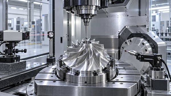
This becomes common with impellers, blisks, angled manifolds, orthopedic parts, and lightweight structural brackets.
In those cases, 5 axis CNC machining CMM inspection should account for line of sight, local surface angle, and collision-free motion.
A strong path plan should do three things
- Approach the feature near the true surface normal whenever possible.
- Avoid sudden probe articulation changes near tight spaces.
- Separate safe travel moves from measurement moves.
This reduces false hits, missed points, and stylus bending during contact.
It also improves repeatability when the same program runs across shifts and operators.
When surface profile is critical, spread points across peaks, valleys, edges, and transition zones.
Do not place all points in easy-to-reach areas.
That creates clean reports with weak truth value.
From a benchmarking view, this is where disciplined inspection separates real process control from cosmetic data collection.
Common Errors That Distort CMM Results
Most 5 axis CNC machining CMM inspection errors are small individually, but they stack quickly.
The report may still look formal and complete, yet the result can be wrong enough to trigger scrap or false acceptance.
Watch for these high-impact mistakes
- Incorrect datum alignment
- Too few points on form-critical features
- Using the wrong stylus diameter compensation
- Measuring on burrs, chips, or coolant residue
- Ignoring thermal differences between part and room
- Clamping the part in a way that deforms thin sections
- Assuming CAD nominal matches the latest print revision
- Running outdated probe calibration files
Alignment errors are especially dangerous.
If the datum frame is built from unstable or damaged surfaces, every downstream feature can shift in the report.
That often looks like a machining problem, even when the machine produced the part correctly.
Another common issue is under-sampling.
A bore checked with four points may appear acceptable, while a scan reveals lobing from tool wear or chatter.
In 5 axis CNC machining CMM inspection, sparse data is not always efficient data.
A Practical Inspection Workflow That Holds Up on the Shop Floor
A consistent workflow prevents many of the errors above before they reach the report.
It also shortens troubleshooting when a result looks suspicious.
Use this sequence
- Clean the part and verify no burrs remain on datum or contact surfaces.
- Confirm drawing revision, CAD model, and inspection program match.
- Stabilize part temperature before measuring tight tolerances.
- Fixture the part with minimal distortion and strong repeatability.
- Qualify the probe setup and confirm stylus condition.
- Build alignment from the correct datum strategy.
- Measure critical features first and review results before running full output.
- Recheck any outlier with an alternate path or point pattern.
This workflow makes 5 axis CNC machining CMM inspection more stable across different jobs and different people.
It also creates better traceability when quality, engineering, and production need to review a disputed result.
How Better Inspection Supports Real Manufacturing Decisions
Good inspection does more than separate pass from fail.
It shows whether the process is drifting, whether tool wear is building, and whether fixture logic still fits the part family.
That is why 5 axis CNC machining CMM inspection matters across advanced manufacturing sectors tracked by TechStat Vanguard.
In aerospace, it protects positional and profile integrity on safety-critical parts.
In robotics and automation, it supports motion accuracy and assembly consistency.
In sensors and edge AI hardware, it helps maintain alignment, enclosure fit, and thermal interface precision.
The bigger point is straightforward.
When measurement strategy becomes disciplined, the data becomes useful for action, not just documentation.
Start with critical features, choose a probe strategy that matches the geometry, and challenge any result that depends on weak alignment or thin sampling.
That approach turns 5 axis CNC machining CMM inspection into a real process control tool, which is exactly where tight-tolerance manufacturing gains ground.
Search News
Hot Articles
- Carbon Fiber StructuresHow to Specify Aerospace Carbon Fiber Assemblies for Lightweight, Load-Bearing PartsJul 11, 2026
- Machine VisionXiaomi, Alibaba DAMO Academy Drive Open-Source Robotics Model Ecosystem, Lowering Algorithm Development Barriers for Overseas SMEs Adopting Chinese Robotics SolutionsMar 30, 2026
- Cobots & ArmsShanxi 'AI+' Conference Showcases Embodied Intelligence with Multinational Buyer Engagement: Key Industry ImplicationsMar 30, 2026
Popular Tags
Recommended News
 Jul 11, 2026How to Specify Aerospace Carbon Fiber Assemblies for Lightweight, Load-Bearing PartsAerospace carbon fiber assemblies: learn how to specify laminate design, load data, joining methods, and inspection controls for lighter, reliable load-bearing aerospace parts.Elena Rostova (UAV Systems Researcher)
 Mar 30, 2026Xiaomi, Alibaba DAMO Academy Drive Open-Source Robotics Model Ecosystem, Lowering Algorithm Development Barriers for Overseas SMEs Adopting Chinese Robotics SolutionsXiaomi & Alibaba DAMO Academy's open-source robotics models lower algorithm barriers for global SMEs. Boost efficiency in manufacturing, logistics & smart retail with ROS 2 compatible solutions.TSV Data Lab
 Mar 30, 2026Shanxi 'AI+' Conference Showcases Embodied Intelligence with Multinational Buyer Engagement: Key Industry ImplicationsShanxi 'AI+' Conference highlights embodied intelligence with Tesla, Ubtech & Jiantao showcasing multimodal robotics. 40+ global buyers validated tech on-site, creating new B2B channels for industrial automation & AI solutions.Chen Wei (Automation Lead Engineer)
 Mar 30, 2026Zhongguancun Unveils 6G Integrated Sensing-Computing-Intelligence Platform to Empower Embodied Robots for Global Industrial ApplicationsZhongguancun's new 6G platform revolutionizes industrial robotics with <10ms latency, empowering global automotive, logistics & port automation. Discover how this tech boosts China's smart manufacturing exports.TSV Data Lab
 Mar 30, 2026Mech-Mind Tianjin Embodied Intelligence R&D and Production Base Goes Live, Cutting Delivery Time by 20%–30% for Global Customized AMR+Vision SolutionsMech-Mind's Tianjin AMR+Vision production base cuts delivery time by 20%-30% for欧美 & Latin American markets. Discover how this PLd-certified facility accelerates customized robotics solutions for smart manufacturing and logistics.Chen Wei (Automation Lead Engineer)
 Mar 30, 2026Boao Forum Reveals 'Co-evolution of Big and Small Brains' Trend in Humanoid Robots, China's Embodied Intelligence Accelerates Adaptation to Overseas Manufacturing Service ScenariosDiscover how China's humanoid robots, featuring 'Co-evolution of Big and Small Brains,' are revolutionizing global manufacturing. Learn about Embodied Tian Gong 3.0's ISO compliance and overseas deployment at Boao Forum 2026.Chen Wei (Automation Lead Engineer)
 Mar 30, 2026China Railway Industrial Secures Patent for Embodied Robotics in Material Handling, Boosting High-Precision Delivery Capabilities for Overseas Infrastructure and Manufacturing ProjectsChina Railway Industrial's new patent for embodied robotics in material handling boosts high-precision delivery for global infrastructure & manufacturing. Discover how this innovation enhances logistics accuracy in automotive, rail transit & EPC projects.Chen Wei (Automation Lead Engineer)
 Oct 04, 2026CAD/CAM Benchmarking in the GCC: What Manufacturers Should Ask a ConsultantCAD CAM benchmark consultant GCC guide: learn the key questions manufacturers should ask to validate post-processors, workflows, machine performance, and production risk.Victor Lin (Chief Software Architect)
 Oct 03, 2026Selecting Automotive Radar Sensor Modules for ADAS Range, Resolution, and IntegrationAutomotive radar sensor module selection guide for ADAS: compare range, resolution, field of view, latency, and integration to build safer, reliable vehicle systems.TSV Data Lab
 Oct 02, 2026How to Qualify Machined Parts Suppliers for Hard Tech ProgramsHard tech supply chain machined parts demand rigorous supplier qualification. Learn how to assess capability, traceability, quality controls, and delivery resilience.Dr. Marcus Vance
 Oct 01, 2026How to Select an Outdoor Security Radar Sensor for Perimeter Detection?Outdoor security radar sensor selection guide: compare range, accuracy, false-alarm control, integration, and field testing for reliable perimeter detection.TSV Data Lab
 Sep 30, 2026How to Evaluate Solid-State LiDAR Hardware for Outdoor Autonomous VehiclesSolid state LiDAR hardware evaluation guide for outdoor autonomous vehicles—compare range, point-cloud quality, environmental resilience, integration, and safety.TSV Data Lab
 Sep 29, 2026ISO 9283 Repeatability: How to Evaluate Cobot Positioning PerformanceISO 9283 cobot repeatability explained: learn how payload, reach, approach direction, and test conditions affect positioning performance and cell capability.Chen Wei (Automation Lead Engineer)
 Oct 04, 2026How Should You Compare 5-Axis CNC Machine Accuracy Claims?How do I compare 5-axis CNC machine accuracy claims? Learn how to assess standards, thermal stability, TCP accuracy, and real-world test evidence.Dr. Marcus Vance
 Oct 03, 2026Is Edge Computing Necessary for Real-Time Quality Inspection?Is industrial edge computing necessary for real-time quality inspection? Explore how latency, data volume, reliability, and control integration shape the right architecture.TSV Data Lab
 Oct 02, 2026What Documents Prove a Precision Machining Supplier Can Hold Tolerance?What documents prove a precision machining supplier can hold tolerance? Explore certificates, FAI reports, calibration, SPC, and traceability evidence to qualify suppliers with confidence.Dr. Marcus Vance
 Oct 01, 2026Can a Machining Supplier Meet Aerospace Fatigue Testing Requirements?Can a machining supplier meet aerospace fatigue testing requirements? Learn the traceability, process control, and test evidence needed for reliable aerospace parts.Dr. Marcus Vance
 Sep 30, 2026Which Industrial Robot Specifications Matter for High-Precision Assembly?Which industrial robot specifications matter most for high-precision assembly? Explore repeatability, accuracy, stiffness, vibration, calibration, and force control for reliable yields.Chen Wei (Automation Lead Engineer)
 Sep 29, 2026How Do You Verify Servo Motor Torque Under Continuous Load?How do I verify servo motor torque under continuous load? Learn RMS torque checks, torque-speed limits, thermal derating, and real-machine testing.Chen Wei (Automation Lead Engineer)
 Oct 02, 2026ZD330 Software Configuration: Verifying Cut-List Import Before PurchaseZD330 software and machine configuration: verify cut-list imports, data mapping, labels, and workflow before purchase to reduce errors and choose with confidence.Victor Lin (Chief Software Architect)
 Sep 28, 2026Spindle Runout Measurement in Germany: DIN Standards, Methods, and Acceptance LimitsSpindle runout measurement Germany: explore DIN standards, proven methods, acceptance limits, and audit-ready practices for reliable machining quality.Dr. Marcus Vance
 Sep 27, 2026How to Select Wall-Mount Edge Devices for Space-Constrained Factory NetworksWall mount edge devices for space-constrained factories: evaluate workload, thermal design, power resilience, cable access, and network reliability for smarter deployments.TSV Data Lab
 Sep 26, 2026Machining Tolerance Analysis: How to Set Limits That Meet Function and Cost TargetsMachining tolerance analysis: learn how to set functional limits, control tolerance stacks, reduce inspection risk, and balance precision with production cost.Dr. Marcus Vance
 Sep 25, 2026How to Evaluate an Industrial Infrastructure Data Platform for Multi-Site OperationsIndustrial infrastructure data platform evaluation guide for multi-site operations: compare data quality, edge resilience, interoperability, governance, and scalable proof-of-value criteria.Victor Lin (Chief Software Architect)