
PLC control for packaging machinery: why stop time is still unstable
Publication Date
author
In high-speed production, PLC control for packaging machinery should deliver repeatable stop performance, yet many operators still see unstable stop time that affects cut accuracy, seal quality, and overall uptime. This article explains why the problem persists, from signal delay and mechanical inertia to tuning errors and sensor mismatch, helping users identify root causes and improve line stability with engineering-based insight.
Why does unstable stop time still happen in PLC control for packaging machinery?
Many users assume the PLC itself is the only reason a machine stops late or early. In reality, unstable stop time in plc control for packaging machinery is usually a system-level issue. The PLC may send the stop command correctly, but the final stop point depends on how quickly the input is detected, how fast the logic scan responds, how the output module switches, how the drive decelerates, and how much inertia is stored in rollers, jaws, belts, film, and product flow.
This is why two packaging lines with the same PLC brand can behave very differently. One line may stop within a tight and repeatable window, while another shows random drift. The difference often comes from the relationship between software timing and mechanical behavior. If the machine is running faster, carries heavier rotating parts, or has more backlash in the transmission path, the same stop signal may produce a different stop result.
Operators also need to distinguish between three symptoms: stop delay, stop overshoot, and stop inconsistency. Stop delay means the machine usually stops later than expected. Overshoot means the machine passes the target point because inertia is not controlled well. Inconsistency means the stop point changes from cycle to cycle even under the same recipe. Each symptom points to a different root cause, so treating them as one generic “PLC problem” often wastes troubleshooting time.
What parts of the stop sequence should operators check first?
A practical way to diagnose plc control for packaging machinery is to break the stop event into stages. When users observe the process in this sequence, the source of variation becomes easier to isolate.
For operators, the fastest first check is usually the sensor and the drive. If the sensor trigger point drifts because of dust, reflective film, or poor mounting, the PLC receives a bad reference. If the drive deceleration setting is too soft, the system cannot hold a consistent stop point even with good PLC logic. Looking at the event chain in order prevents random adjustments that create more instability.
Is the problem really in the PLC, or is it more often in sensors, drives, and mechanics?
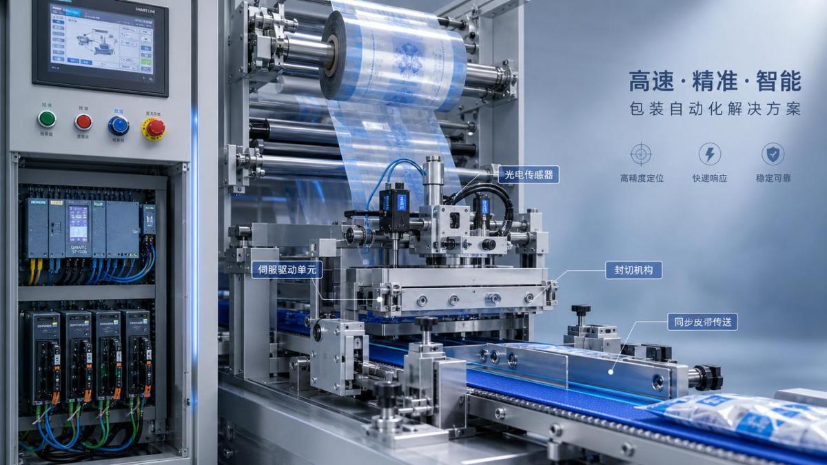
In most packaging applications, the PLC is only one link in the timing chain. The real issue often sits outside the controller. For example, photoelectric sensors may react differently when switching from clear film to printed film. A registration mark sensor may be accurate at medium speed but become noisy at high web speed. A pneumatic knife or sealing jaw may respond differently as air pressure changes over the shift.
Likewise, a servo axis with poor tuning can create stop variability that appears to be a logic fault. If the position loop is underdamped, the axis may oscillate slightly around the target. If the load inertia ratio is high and deceleration is aggressive, the drive may compensate differently depending on product weight or film tension. This is common in horizontal form-fill-seal machines, cartoners, flow wrappers, and labeling systems where acceleration and stop precision are tightly linked.
Mechanical wear is another frequent source. Operators may focus on PLC control for packaging machinery because the symptom appears on the HMI or in machine timing, but worn couplings, slipping timing belts, loose chain drives, and brake fatigue can all turn a stable command into an unstable stop point. In simple terms, the PLC can only control what the physical system is capable of repeating.
How do scan time, communication delay, and logic design affect stop accuracy?
When users discuss plc control for packaging machinery, they often overlook timing architecture. A standard cyclic scan may be acceptable for general machine functions, but critical stop events at high speed may require faster tasks, hardware interrupts, or direct high-speed input processing. If a machine runs at high throughput, even a few milliseconds of inconsistent delay can shift the cut or seal position enough to create visible defects.
Communication networks can add another layer. If the stop command moves through a fieldbus to a remote I/O rack or drive, the update cycle and jitter matter. Most of the time this delay is small and predictable, but if the system is heavily loaded or poorly configured, operators may see different response times under different machine conditions. This is especially important where registration control, encoder feedback, and motion synchronization share the same control network.
Logic design also matters. Some programs rely on multiple permissives, filters, latches, or interlocked sequences before a stop command reaches the output. This may improve safety or process order, but it can also create hidden timing differences. A common mistake is to place critical stop logic in a slower task while expecting motion-level precision. Another is using long debounce filters on sensors that need fast edge detection. Good engineering practice is to map the timing path clearly and identify where deterministic control ends and variable delay begins.
What operating conditions make stop time drift more obvious on packaging lines?
Stop instability is usually more visible when production conditions change. High speed is the most obvious factor, but it is not the only one. Product length variation, film tension changes, jaw temperature, roller contamination, and even different recipes can expose weaknesses that stay hidden at lower speeds.
For example, a line may perform well during dry running but drift during actual packaging because the product adds mass and changes conveyor loading. A seal head may stop consistently when cold, then overshoot slightly after thermal expansion changes alignment. A machine may hold position during short batches but become inconsistent after several hours because a brake coil heats up or compressed air quality drops. These are not unusual failures; they are normal consequences of a real production environment acting on a marginal control design.
Operators should also watch for instability during recipe changeovers. If stop timing constants are copied between products without considering package length, jaw mass, or web properties, the machine may seem random when it is actually misapplied. In that sense, effective PLC control for packaging machinery depends not only on automation hardware but also on disciplined recipe management and process validation.
What are the most common troubleshooting mistakes users make?
The first mistake is adjusting PLC timers before proving the trigger source. If the sensor signal is unstable, changing logic delays only masks the symptom for one condition and worsens another. The second mistake is retuning drives without checking the mechanics. No servo tuning can permanently fix backlash, slippage, or brake wear. The third mistake is using average stop performance as the acceptance standard. What matters is repeatability under normal production variation, not a single successful test cycle.
Another common error is ignoring timestamped data. Operators often rely on visual judgment, but a stop event that “looks late” may actually be a result of earlier registration drift, encoder pulse loss, or asynchronous output switching. Capturing sensor input, PLC event timing, and drive status in sequence is far more effective than guessing. This fits the TSV approach to industrial troubleshooting: strip away assumptions, compare measurable parameters, and follow the data path from detection to motion response.
A final mistake is treating safety stop, normal stop, and positional stop as the same control event. Emergency stop behavior, controlled process stop, and mark-based indexed stop use different logic and different drive actions. If users do not separate these stop categories, troubleshooting becomes confusing and inconsistent.
How can operators improve PLC control for packaging machinery without a full redesign?
Not every unstable stop problem requires a new machine or a major retrofit. Many improvements come from disciplined, layered checks. Start by confirming sensor health: mounting rigidity, lens cleanliness, signal repeatability, cable shielding, and the correct detection mode for the material. Then verify PLC task timing, scan loading, and whether critical stop signals should move into faster processing paths.
Next, review the drive and motion settings. Look at deceleration ramps, brake timing, following error, torque limits, and any active filter functions. Compare these settings between machines if one line performs better than another. After that, inspect the mechanical chain: shafts, couplings, pulleys, chains, belts, bearings, and braking surfaces. Small mechanical looseness often produces larger stop variation than users expect.
It is also useful to create a standard stop-performance check during preventive maintenance. Record stop repeatability at defined speed, load, and material conditions. If drift increases over time, maintenance can intervene before scrap or downtime rises. This turns plc control for packaging machinery from a reactive complaint into a measurable process capability issue.
- Verify sensor trigger consistency before adjusting timers.
- Check PLC scan time and network update timing under real load.
- Confirm servo or VFD stop mode matches the required stop behavior.
- Inspect mechanical wear points that influence backlash and inertia response.
- Validate stop repeatability by recipe, speed, and product type.
When should a user escalate from adjustment to engineering review or supplier support?
If stop variation appears only at the top 10% to 20% of production speed, a tuning review may be enough. If instability occurs across all speeds, across different products, or grows worse over time, the issue likely involves deeper mechanical or architectural limits. Users should escalate when normal adjustments fail to deliver repeatable results, when product quality losses become measurable, or when safety-related stopping performance is unclear.
At that stage, the right discussion is not “Which PLC brand is better?” but “What are the measured delays, inertia conditions, deceleration profiles, and sensor characteristics of this machine?” A good engineering review should include actual event timing, drive diagnostics, and a mechanical condition check. That is the fastest path to separating software delay from physical response limits.
What should users ask first before confirming a solution, upgrade, or supplier proposal?
Before approving changes to plc control for packaging machinery, users should ask a short set of practical questions. What is the current stop repeatability in milliseconds or position error? Which signal starts the stop sequence, and how repeatable is that signal? Is the stop event processed in a deterministic fast task or a general scan? What deceleration mode does the drive use, and how does it behave under full product load? Are there worn mechanical components that change motion response? Which recipes or materials show the worst drift?
These questions help users move from symptom chasing to parameter-based decision making. For operators, maintenance teams, and production supervisors, that is the most reliable way to improve stop stability without wasting time on blind adjustments. If further confirmation is needed for a specific machine, parameter set, upgrade path, implementation timeline, or supplier communication, it is best to begin with measured stop data, actual line speed, product format, sensor type, drive model, and the exact defect pattern seen in production.
Search News
Hot Articles
- Carbon Fiber StructuresHow to Specify Aerospace Carbon Fiber Assemblies for Lightweight, Load-Bearing PartsJul 11, 2026
- Machine VisionXiaomi, Alibaba DAMO Academy Drive Open-Source Robotics Model Ecosystem, Lowering Algorithm Development Barriers for Overseas SMEs Adopting Chinese Robotics SolutionsMar 30, 2026
- Cobots & ArmsShanxi 'AI+' Conference Showcases Embodied Intelligence with Multinational Buyer Engagement: Key Industry ImplicationsMar 30, 2026
Popular Tags
Recommended News
 Jul 11, 2026How to Specify Aerospace Carbon Fiber Assemblies for Lightweight, Load-Bearing PartsAerospace carbon fiber assemblies: learn how to specify laminate design, load data, joining methods, and inspection controls for lighter, reliable load-bearing aerospace parts.Elena Rostova (UAV Systems Researcher)
 Mar 30, 2026Xiaomi, Alibaba DAMO Academy Drive Open-Source Robotics Model Ecosystem, Lowering Algorithm Development Barriers for Overseas SMEs Adopting Chinese Robotics SolutionsXiaomi & Alibaba DAMO Academy's open-source robotics models lower algorithm barriers for global SMEs. Boost efficiency in manufacturing, logistics & smart retail with ROS 2 compatible solutions.TSV Data Lab
 Mar 30, 2026Shanxi 'AI+' Conference Showcases Embodied Intelligence with Multinational Buyer Engagement: Key Industry ImplicationsShanxi 'AI+' Conference highlights embodied intelligence with Tesla, Ubtech & Jiantao showcasing multimodal robotics. 40+ global buyers validated tech on-site, creating new B2B channels for industrial automation & AI solutions.Chen Wei (Automation Lead Engineer)
 Mar 30, 2026Zhongguancun Unveils 6G Integrated Sensing-Computing-Intelligence Platform to Empower Embodied Robots for Global Industrial ApplicationsZhongguancun's new 6G platform revolutionizes industrial robotics with <10ms latency, empowering global automotive, logistics & port automation. Discover how this tech boosts China's smart manufacturing exports.TSV Data Lab
 Mar 30, 2026Mech-Mind Tianjin Embodied Intelligence R&D and Production Base Goes Live, Cutting Delivery Time by 20%–30% for Global Customized AMR+Vision SolutionsMech-Mind's Tianjin AMR+Vision production base cuts delivery time by 20%-30% for欧美 & Latin American markets. Discover how this PLd-certified facility accelerates customized robotics solutions for smart manufacturing and logistics.Chen Wei (Automation Lead Engineer)
 Mar 30, 2026Boao Forum Reveals 'Co-evolution of Big and Small Brains' Trend in Humanoid Robots, China's Embodied Intelligence Accelerates Adaptation to Overseas Manufacturing Service ScenariosDiscover how China's humanoid robots, featuring 'Co-evolution of Big and Small Brains,' are revolutionizing global manufacturing. Learn about Embodied Tian Gong 3.0's ISO compliance and overseas deployment at Boao Forum 2026.Chen Wei (Automation Lead Engineer)
 Mar 30, 2026China Railway Industrial Secures Patent for Embodied Robotics in Material Handling, Boosting High-Precision Delivery Capabilities for Overseas Infrastructure and Manufacturing ProjectsChina Railway Industrial's new patent for embodied robotics in material handling boosts high-precision delivery for global infrastructure & manufacturing. Discover how this innovation enhances logistics accuracy in automotive, rail transit & EPC projects.Chen Wei (Automation Lead Engineer)
 Sep 29, 2026ISO 9283 Repeatability: How to Evaluate Cobot Positioning PerformanceISO 9283 cobot repeatability explained: learn how payload, reach, approach direction, and test conditions affect positioning performance and cell capability.Chen Wei (Automation Lead Engineer)
 Sep 28, 2026Spindle Runout Measurement in Germany: DIN Standards, Methods, and Acceptance LimitsSpindle runout measurement Germany: explore DIN standards, proven methods, acceptance limits, and audit-ready practices for reliable machining quality.Dr. Marcus Vance
 Sep 27, 2026How to Select Wall-Mount Edge Devices for Space-Constrained Factory NetworksWall mount edge devices for space-constrained factories: evaluate workload, thermal design, power resilience, cable access, and network reliability for smarter deployments.TSV Data Lab
 Sep 26, 2026Machining Tolerance Analysis: How to Set Limits That Meet Function and Cost TargetsMachining tolerance analysis: learn how to set functional limits, control tolerance stacks, reduce inspection risk, and balance precision with production cost.Dr. Marcus Vance
 Sep 25, 2026How to Evaluate an Industrial Infrastructure Data Platform for Multi-Site OperationsIndustrial infrastructure data platform evaluation guide for multi-site operations: compare data quality, edge resilience, interoperability, governance, and scalable proof-of-value criteria.Victor Lin (Chief Software Architect)
 Sep 24, 2026How to Select Machine Vision Optics for Accurate Inspection at Different Working DistancesMachine vision optics selection guide for accurate inspection at every working distance. Compare FOV, pixel scale, DOF, distortion, lighting, and telecentric options.TSV Data Lab
 Sep 23, 2026How to Evaluate a Machine Vision System Integrator for High-Speed Inspection LinesChoose a machine vision system integrator with proven expertise in high-speed inspection, reliable reject timing, robust optics, and measurable acceptance criteria.TSV Data Lab
 Sep 28, 2026When is a SCADA API the right choice for connecting plant systems?SCADA API guide: learn when governed plant data integration improves traceability, security, and scalability—without compromising real-time control.Victor Lin (Chief Software Architect)
 Sep 27, 2026How SCADA data integration improves traceability across production linesSCADA data integration connects production-line data to improve traceability, accelerate quality investigations, and strengthen safety decisions.Victor Lin (Chief Software Architect)
 Sep 26, 2026What to define before starting SCADA integration planningSCADA integration planning starts with clear scope, control boundaries, data models, cybersecurity, and testing. Discover the definitions that reduce risk and costly rework.Victor Lin (Chief Software Architect)
 Sep 25, 2026How a smart factory with Industrial IoT reduces production blind spotsDiscover how a smart factory with Industrial IoT turns real-time machine, quality, and workflow data into actionable insights that reduce production blind spots and delivery risks.Victor Lin (Chief Software Architect)
 Sep 24, 2026When does Industrial IoT make smart manufacturing easier to scale?Smart manufacturing Industrial IoT scales when trusted data, interoperable systems, and secure workflows turn connected assets into measurable gains.TSV Data Lab
 Sep 23, 2026What drives ultra-precision machining cost at 1-micron tolerance?Ultra precision machining cost per part at 1 micron tolerance depends on process, material, metrology, and yield. Learn how to compare quotes confidently.Dr. Marcus Vance
 Sep 22, 2026Drone Engine-T550CC Applications: Build the UAV Power System Around the MissionAn application guide for Drone Engine-T550CC integration, covering payload planning, airframe matching, cooling, fuel, vibration, test procedures, documentation, and service preparation.Elena Rostova (UAV Systems Researcher)
 Sep 22, 2026How to Evaluate Industrial Edge Computing Vendors for Factory DeploymentIndustrial edge computing vendor evaluation guide for factories: compare latency, protocol fit, reliability, security, and lifecycle support before deployment.TSV Data Lab
 Sep 21, 2026Drone Payload Integration: Matching Power, Data, and Center of Gravity for Reliable FlightsDrone payload integration made practical: balance power, data, center of gravity, and endurance to build safer, more reliable mission-ready flights.Elena Rostova (UAV Systems Researcher)
 Sep 20, 2026Autonomous Navigation Pricing: Cost Drivers and Budget Benchmarks for AMR ProjectsAutonomous navigation price explained: compare AMR cost drivers, software, sensors, integration, safety, and lifecycle budgets to build a scalable project plan.Chen Wei (Automation Lead Engineer)























