How to Evaluate Robotics Integration MTBF for More Reliable Automation Projects
Publication Date
author
How to Evaluate Robotics Integration MTBF for More Reliable Automation Projects
For technical evaluators planning dependable automation deployments, robotics integration MTBF is more than a reliability metric. It is a practical decision tool for judging resilience, maintenance exposure, and lifecycle cost.
The problem is simple. Many suppliers publish attractive uptime claims, yet few explain test boundaries, duty cycles, or failure definitions. That gap makes direct comparison risky.
A disciplined robotics integration MTBF review helps teams separate marketing language from engineering evidence. It also improves specification writing, supplier qualification, and maintenance forecasting.
Why Robotics Integration MTBF Matters at System Level
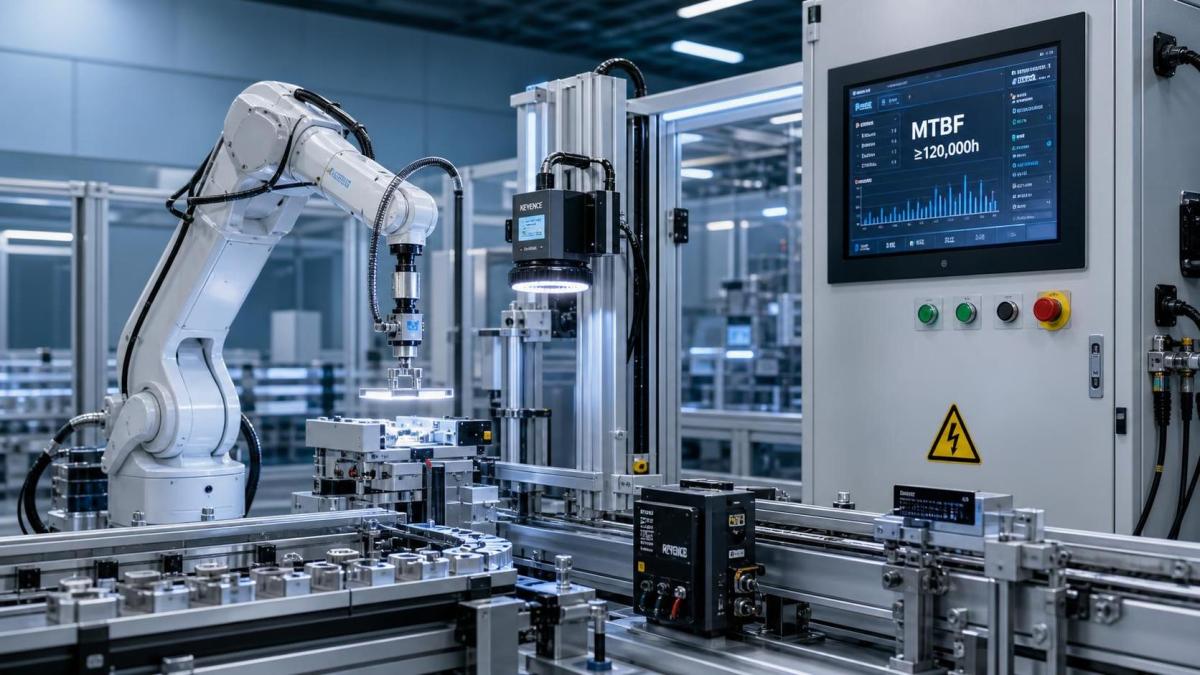
MTBF, or Mean Time Between Failures, only becomes useful when evaluated at the integration level. A robot cell is never just a robot arm.
Real automation systems include controllers, drives, end effectors, sensors, cables, safety circuits, HMIs, fieldbus networks, and upstream process dependencies. Any weak point can stop production.
That is why robotics integration MTBF should reflect the full operating architecture. Looking only at manipulator MTBF often hides the most frequent causes of downtime.
From a recent market shift, the more obvious signal is tighter coupling. Edge analytics, machine vision, AMR docking, and flexible tooling increase capability, but also increase failure pathways.
In practical terms, robotics integration MTBF affects three decisions. It shapes system availability, planned spares strategy, and the true cost of support over several years.
Start with a Precise Failure Definition
Before comparing vendors, define what counts as a failure. This step sounds basic, but it prevents most MTBF misunderstandings.
For robotics integration MTBF, failure should mean a condition that stops intended function or forces performance outside an accepted threshold. That threshold must be written, not implied.
A precise failure definition often includes these categories:
- Hard failures, such as servo faults, safety trips without cause, controller crashes, or damaged harnesses.
- Functional failures, such as missed picks, unstable vision alignment, or failed handshakes with PLCs.
- Performance failures, such as cycle time drift beyond tolerance or repeatability loss that breaks quality targets.
- Intermittent failures that self-clear but still create downtime, scrap, or operator intervention.
This also means near-fail states should not be ignored. Intermittent communication resets may look minor, yet they often predict deeper integration instability.
When the failure definition is vague, robotics integration MTBF becomes inflated. When it is explicit, supplier claims become easier to audit.
Check the Test Conditions Behind the Number
A single MTBF value without context has limited value. The number only matters when tied to operating conditions that resemble the intended deployment.
Ask for the conditions used to calculate robotics integration MTBF. Good suppliers can describe them in measurable terms.
- Duty cycle: hours per day, starts and stops, and average utilization.
- Load profile: payload, inertia, tool mass, center of gravity, and acceleration pattern.
- Environment: dust, vibration, humidity, washdown exposure, temperature swing, and EMC conditions.
- Process behavior: pick-and-place, welding, dispensing, inspection, palletizing, or machine tending.
- Support architecture: local buffering, redundancy, remote diagnostics, and maintenance interval assumptions.
This is where many comparisons break down. A published robotics integration MTBF from a light-duty lab cell does not represent a high-acceleration, multi-shift production line.
The same applies to mission profile changes. A cobot handling soft packaging behaves differently from one tending CNC equipment with coolant mist and thermal variation.
Evaluate the Weakest Links in the Integration Stack
Robotics integration MTBF should be traced by subsystem, not treated as one abstract figure. That approach reveals where downtime is actually generated.
In most automation projects, failures cluster around integration boundaries. Connectors loosen, cables fatigue, protocols mismatch, and tolerances stack across devices.
Focus the review on these common reliability drivers:
- Motion chain reliability, including servo drives, gearboxes, brakes, and thermal loading.
- End-of-arm tooling durability, especially pneumatic wear, gripper jaw alignment, and sensor contamination.
- Cable management life, especially at high bend rates or rotating joints.
- Vision and sensor stability under lighting change, reflective surfaces, and vibration.
- PLC, robot, and MES handshake integrity across network events or firmware changes.
- Safety system behavior, including nuisance trips and recovery complexity.
A useful supplier review asks for failure mode distribution, not only total robotics integration MTBF. If 60 percent of downtime comes from tooling, the mitigation plan changes immediately.
Use Field Data, Not Just Theoretical Models
Theoretical MTBF calculations are valuable, but field evidence matters more. Reliability models can estimate behavior. Operational records show what really fails.
Ask vendors to separate modeled robotics integration MTBF from observed robotics integration MTBF. Those are not the same thing.
Higher confidence comes from a combination of sources:
- Installed base hours across similar applications.
- Warranty return patterns by subsystem.
- Service logs with root-cause categories.
- Corrective action records after firmware or hardware revisions.
- Customer site performance under comparable shift patterns.
This is especially important in newer automation categories. AMR-robot combinations, AI-assisted vision, and mixed-vendor cells may have limited long-run history.
When field history is still thin, require conservative assumptions. That may include derating, extra spares, staged ramp-up, or more intensive acceptance testing.
Compare MTBF Together with MTTR and Availability
A strong robotics integration MTBF number does not guarantee high output. Recovery speed also matters.
That is why technical evaluation should pair MTBF with MTTR, or Mean Time To Repair. Availability depends on both values.
Two systems may show similar robotics integration MTBF, yet one returns to production in ten minutes while the other needs two hours and specialist support.
Use a simple comparison table during supplier review:
This broader view is usually more useful than chasing the largest MTBF value on a datasheet.
Build a Practical Evaluation Framework
A disciplined framework keeps robotics integration MTBF reviews consistent across suppliers and project phases. It also creates a traceable basis for approval decisions.
A practical workflow usually includes these steps:
- Define the production mission profile, including shifts, throughput, payload variation, and environmental stress.
- Write a failure taxonomy for the integrated cell, not just the robot OEM components.
- Request subsystem-level reliability evidence and service history from each supplier.
- Normalize robotics integration MTBF claims to comparable operating assumptions.
- Review MTTR, spare parts lead time, and remote support readiness.
- Run FAT and SAT plans that stress the known weak points.
- Capture early-life failures during ramp-up and feed them back into the acceptance baseline.
This approach aligns well with TSV’s core principle. Parameters do not lie, but only when the boundary conditions are honestly stated.
Common Mistakes That Distort Robotics Integration MTBF
Several recurring mistakes make robotics integration MTBF look stronger than actual site performance.
- Using component MTBF as a substitute for system MTBF.
- Ignoring software and communication faults because hardware appears healthy.
- Excluding brief stoppages that still reduce throughput and operator efficiency.
- Applying clean-room assumptions to harsh industrial environments.
- Treating all applications as equal despite different motion dynamics and contamination loads.
- Accepting unsupported estimates without confidence intervals or sample size disclosure.
More importantly, these mistakes create expensive procurement errors. They shorten maintenance cycles, increase debugging effort, and delay return on automation investment.
What a Strong Supplier Answer Looks Like
A credible supplier does not defend robotics integration MTBF with adjectives. They explain assumptions, limits, and corrective actions with measurable detail.
The strongest answers usually include a stated operating profile, subsystem failure ranking, evidence from comparable sites, and a maintenance model linked to spare parts planning.
They also acknowledge uncertainty. That is often the clearest sign that the reliability model was built by engineers, not marketers.
In the end, robotics integration MTBF works best as part of a wider technical standard for supplier selection. It should guide questions, not replace engineering judgment.
Final Evaluation Takeaway
For more reliable automation projects, evaluate robotics integration MTBF at the system level, under realistic duty conditions, and alongside MTTR, availability, and field evidence.
That shift changes MTBF from a brochure number into a working decision tool. It helps teams reduce qualification risk, tighten specifications, and deploy automation with fewer surprises.
When reviewing the next proposal, ask one practical question first: what exactly failed, under what conditions, and how often in the real world? That is where reliable engineering starts.
Search News
Hot Articles
- Carbon Fiber StructuresHow to Specify Aerospace Carbon Fiber Assemblies for Lightweight, Load-Bearing PartsJul 11, 2026
- Machine VisionXiaomi, Alibaba DAMO Academy Drive Open-Source Robotics Model Ecosystem, Lowering Algorithm Development Barriers for Overseas SMEs Adopting Chinese Robotics SolutionsMar 30, 2026
- Cobots & ArmsShanxi 'AI+' Conference Showcases Embodied Intelligence with Multinational Buyer Engagement: Key Industry ImplicationsMar 30, 2026
Popular Tags
Recommended News
 Jul 11, 2026How to Specify Aerospace Carbon Fiber Assemblies for Lightweight, Load-Bearing PartsAerospace carbon fiber assemblies: learn how to specify laminate design, load data, joining methods, and inspection controls for lighter, reliable load-bearing aerospace parts.Elena Rostova (UAV Systems Researcher)
 Mar 30, 2026Xiaomi, Alibaba DAMO Academy Drive Open-Source Robotics Model Ecosystem, Lowering Algorithm Development Barriers for Overseas SMEs Adopting Chinese Robotics SolutionsXiaomi & Alibaba DAMO Academy's open-source robotics models lower algorithm barriers for global SMEs. Boost efficiency in manufacturing, logistics & smart retail with ROS 2 compatible solutions.TSV Data Lab
 Mar 30, 2026Shanxi 'AI+' Conference Showcases Embodied Intelligence with Multinational Buyer Engagement: Key Industry ImplicationsShanxi 'AI+' Conference highlights embodied intelligence with Tesla, Ubtech & Jiantao showcasing multimodal robotics. 40+ global buyers validated tech on-site, creating new B2B channels for industrial automation & AI solutions.Chen Wei (Automation Lead Engineer)
 Mar 30, 2026Zhongguancun Unveils 6G Integrated Sensing-Computing-Intelligence Platform to Empower Embodied Robots for Global Industrial ApplicationsZhongguancun's new 6G platform revolutionizes industrial robotics with <10ms latency, empowering global automotive, logistics & port automation. Discover how this tech boosts China's smart manufacturing exports.TSV Data Lab
 Mar 30, 2026Mech-Mind Tianjin Embodied Intelligence R&D and Production Base Goes Live, Cutting Delivery Time by 20%–30% for Global Customized AMR+Vision SolutionsMech-Mind's Tianjin AMR+Vision production base cuts delivery time by 20%-30% for欧美 & Latin American markets. Discover how this PLd-certified facility accelerates customized robotics solutions for smart manufacturing and logistics.Chen Wei (Automation Lead Engineer)
 Mar 30, 2026Boao Forum Reveals 'Co-evolution of Big and Small Brains' Trend in Humanoid Robots, China's Embodied Intelligence Accelerates Adaptation to Overseas Manufacturing Service ScenariosDiscover how China's humanoid robots, featuring 'Co-evolution of Big and Small Brains,' are revolutionizing global manufacturing. Learn about Embodied Tian Gong 3.0's ISO compliance and overseas deployment at Boao Forum 2026.Chen Wei (Automation Lead Engineer)
 Mar 30, 2026China Railway Industrial Secures Patent for Embodied Robotics in Material Handling, Boosting High-Precision Delivery Capabilities for Overseas Infrastructure and Manufacturing ProjectsChina Railway Industrial's new patent for embodied robotics in material handling boosts high-precision delivery for global infrastructure & manufacturing. Discover how this innovation enhances logistics accuracy in automotive, rail transit & EPC projects.Chen Wei (Automation Lead Engineer)
 Oct 23, 2026Choosing Industrial Sensing Systems for Global Plants: Protocol CompatibilityCompare industrial sensing systems international buyers can trust. Explore protocol compatibility, reduce integration risks, and select proven configurations for reliable global plant deployments.TSV Data Lab
 Oct 22, 2026KUKA Showcases Physical AI and iiQKA.AI Vision at NVIDIA GTC BerlinExplore KUKA’s Physical AI showcase at NVIDIA GTC Berlin and discover how iiQKA.AI Vision aims to simplify robotic vision integration and improve 2D and 3D scene recognition.TSV Data Lab
 Oct 22, 2026Robotic Machining of Advanced Composites: What Tolerances Are Achievable?Explore advanced materials machining robotics: discover what drives achievable composite tolerances and how to validate accuracy before investing in your next machining system.Dr. Marcus Vance
 Oct 21, 2026China’s Industrial Robot Exports Near RMB 10 Billion in First Nine Months of 2026China’s industrial robot exports neared RMB 10 billion in January–September 2026, with value rising faster than volume. Explore the data and what it could mean for suppliers.Chen Wei (Automation Lead Engineer)
 Oct 21, 2026Low-Latency Industrial Data Processing: Pricing and Key Cost DriversExplore industrial data latency price drivers, from edge hardware to integration and support. Learn how to compare quotes, verify performance, and avoid unnecessary costs.TSV Data Lab
 Oct 20, 2026KUKA Launches iiQKA.AI Vision to Simplify Industrial Image ProcessingKUKA iiQKA.AI Vision simplifies industrial image processing with controller-based 2D and 3D vision. Explore drag-and-drop setup for vision-guided automation.TSV Data Lab
 Oct 20, 2026Smart Industrial Edge Devices: Key Criteria for Legacy PLC IntegrationChoose smart industrial edge devices for legacy PLC integration. Discover key criteria for compatibility, data quality, security, and reliable collection without disrupting control.TSV Data Lab
 Oct 19, 2026Choosing a Radar Sensor by Application: Range, Resolution, and Field of ViewSimplify radar sensor application based product selection. Compare range, resolution, and field of view to avoid blind spots and choose with confidence. Explore the guide.TSV Data Lab
 Oct 18, 2026Comparing Material Options for Procurement: Specs, Costs, and Supply RisksExplore procurement oriented technical content on material options, specs, costs, and supply risks. Compare alternatives to cut hidden expenses and make confident sourcing decisions.Dr. Marcus Vance
 Oct 17, 20265-Axis CNC Positioning Accuracy: How to Interpret ISO 230-2 Test ResultsAssess 5 axis CNC machining positioning accuracy with ISO 230-2. Learn to interpret repeatability, reversal error, and test conditions to compare suppliers and make confident acceptance decisions.Dr. Marcus Vance
 Oct 16, 2026Choosing a Rugged Edge AI Box Supplier: Thermal Tests and Lifecycle SupportChoose a rugged edge AI box supplier with proven thermal performance and reliable lifecycle support. Discover the tests and commitments to verify before you buy.TSV Data Lab
 Oct 15, 2026R&D Cost Reduction Services: How to Evaluate Fees, Savings, and ROIEvaluate R&D cost reduction services with confidence. Compare fees, verify savings, and calculate ROI without compromising performance. Discover how to choose a provider that delivers real value.Chen Wei (Automation Lead Engineer)
 Oct 22, 2026How Do You Test AMR Navigation Accuracy in a Warehouse?Test AMR navigation accuracy in warehouses with practical methods for localization, path tracking, and docking. Learn to set tolerances and compare robots before deployment.Chen Wei (Automation Lead Engineer)
 Oct 21, 2026How Should You Balance Cobot Payload Against Reach?Explore cobot payload versus reach to choose the right robot. Learn how tooling, load limits, workspace, and cycle time affect performance—and avoid costly selection mistakes.Chen Wei (Automation Lead Engineer)
 Oct 20, 2026How Do You Measure Industrial IoT Gateway Latency Under Load?Measure industrial IoT gateway latency under load with reliable timestamps, realistic traffic, and tail-latency analysis. Discover how to expose bottlenecks and choose the right gateway.TSV Data Lab
 Oct 19, 2026How Do You Verify That Precision Machined Parts Meet Tolerances?Master precision machining tolerance verification with the right tools, datum setups, and acceptance rules. Learn how to validate parts confidently and reduce costly inspection errors.Dr. Marcus Vance
 Oct 18, 2026What Should an AS9100 Machining Supplier Checklist Include?Build an AS9100 machining supplier checklist that verifies capability, traceability, inspection, and outsourced processes. Discover what to check before approving your next aerospace supplier.Dr. Marcus Vance