How Do You Test AMR Navigation Accuracy in a Warehouse?
Publication Date
author
To test AMR navigation accuracy in a warehouse, measure the robot’s actual position and heading against an independent reference, then repeat representative routes and docking maneuvers under defined operating conditions. A completed mission establishes that the robot reached its destination. It does not establish whether the robot maintained sufficient aisle clearance or aligned accurately enough for a pallet transfer.
The acceptance threshold should come from the warehouse task. Transport through open floor space and engagement with a conveyor require different tolerances. A useful evaluation therefore separates localization accuracy, path tracking, and final docking performance, while recording retries and recovery time. That separation makes vendor comparisons meaningful and helps engineers identify where an apparently successful demonstration could fail in production.
Define the positioning requirement at the working interface
Begin with the location where positioning error has an operational consequence: the pallet entry point, conveyor interface, charging contacts, rack opening, or narrowest section of a route. Define the permitted longitudinal, lateral, and heading errors there. A single circular position tolerance can conceal a problem when the interface permits movement in one direction but restricts it sharply in another.
The reference point matters as much as the tolerance. A vendor may specify accuracy at the robot’s geometric center, while the task depends on a fork tip or load transfer mechanism. Heading error creates additional displacement at an interface located away from the robot center. For a small heading error expressed in radians, the resulting lateral displacement is approximately the distance to the interface multiplied by that error.
Include the rest of the mechanical system in the tolerance budget. Payload placement, fork deflection, fixture alignment, pallet condition, and station movement can consume part of the available allowance. Assigning the entire interface tolerance to navigation leaves no room for those effects. Where a mechanical guide corrects the final alignment, measure both the approach pose and the completed engagement.
Also distinguish accuracy from repeatability. A robot can stop in a tightly grouped cluster that is consistently offset from the target. That behavior is repeatable but inaccurate. Conversely, stops may average close to the target while individual attempts spread beyond the permitted envelope. Record both the average offset and the distribution of individual errors.
Separate three measurements that vendor demonstrations often combine
Localization accuracy: does the robot know where it is?
Compare the robot’s reported pose with an independently measured pose at synchronized times. Position error is the distance between those two positions; heading error is their angular difference, wrapped consistently around the angular boundary. Retain the directional errors as well, because they reveal whether the estimate is biased along or across an aisle.
A robot’s internal confidence estimate is useful diagnostic information, but it does not provide independent ground truth. A localization system can report high confidence while matching an incorrect part of a repetitive rack layout. Test the estimated position itself, including after turns, temporary sensor obstruction, and stops in areas with few distinctive features.
Path tracking: does the robot move within the required corridor?
Measure the actual trajectory relative to the intended route, including cross-track error and heading deviation. For curves, calculate cross-track error against the relevant path segment. Comparing samples solely by timestamp can mistake a harmless delay for a spatial tracking failure.
Dynamic avoidance needs separate treatment. An AMR may deliberately leave its original path to pass an obstacle. Assess that maneuver against the permitted travel corridor, required clearance, and authorized replanning behavior. Otherwise, a valid avoidance maneuver could be scored as inaccurate tracking. Log the active planned path so the comparison reflects what the controller was attempting to execute.
Docking accuracy: can the robot complete the interface task?
Measure the final pose relative to the destination fixture after the specified settling period and before engagement changes the robot’s position. Record first-attempt docking success, corrective maneuvers, elapsed docking time, and the final interface result. A robot that achieves tolerance after several adjustments has different throughput implications from one that achieves it on the first approach.
Docking may use local markers, cameras, reflectors, or mechanical guides that are absent during general travel. Consequently, excellent docking accuracy does not establish equally accurate localization throughout the warehouse. Report the contribution of these aids and include their installation requirements in the comparison.
Choose a ground-truth method that can resolve the tolerance
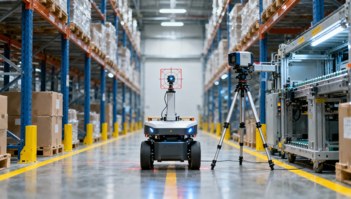
The measurement system must have sufficiently low uncertainty to distinguish acceptable from unacceptable performance. Its suitability depends on the required tolerance, measurement volume, robot speed, visibility, and whether continuous position and heading are needed. Instrument resolution alone is insufficient; calibration, target mounting, synchronization, and coordinate transformations also contribute uncertainty.
- Surveyed checkpoints and fixed gauges: Useful for measuring stationary arrival positions or interface alignment. They can provide a practical docking assessment, but isolated checkpoints cannot reveal deviations between stops.
- Optical motion capture: Can provide continuous position and orientation within a calibrated measurement volume. Coverage, marker visibility, occlusion, and calibration quality determine whether it suits the warehouse test area.
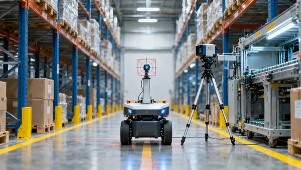
- Laser trackers or tracking survey instruments: Can provide an independent position reference where target tracking and line of sight are maintained. A single tracked point does not independently establish heading; orientation requires additional geometry or another validated measurement method.
- Calibrated overhead cameras: Can support trajectory measurement over a defined area. Lens distortion, mounting stability, target height, image resolution, and lighting must be accounted for before treating the output as ground truth.
Use continuous tracking when the question concerns moving accuracy, and stationary metrology when the main question concerns the final interface pose. Combining the two can be more practical than instrumenting every aisle to the same precision. Any unmeasured route sections should remain outside the claimed continuous accuracy result.
Register the warehouse map and measurement system to a common coordinate frame using fixed references. Establish that transformation before evaluation and keep it fixed. Refitting coordinates separately for each run can remove the drift or systematic offset the test is intended to expose. Likewise, document the rigid transformation between the tracked target and the robot’s working reference point.
Synchronize timestamps and account for measurement latency. During motion, a timing mismatch produces an apparent position error roughly proportional to speed multiplied by the mismatch. Validate synchronization before attributing discrepancies to navigation. Treat tracking dropouts as missing measurements and report their extent; do not silently interpolate through events where accuracy may have deteriorated.
Compare performance across conditions that change the result
A controlled baseline is useful for identifying bias and checking the measurement setup. Run the robot through straight travel, turns, stops, and docking with a stable layout and a defined load. Then introduce conditions that represent the intended operation. The purpose is to discover which conditions change the error distribution or recovery behavior.
Payload testing should include the relevant mass range and permitted center-of-gravity positions. Loading can change braking, traction, and chassis attitude. Compare travel in both directions where the drive configuration or load geometry makes direction relevant. Record the installed payload and its placement rather than describing a run simply as “loaded.”
Test at the configured operating speeds, including acceleration, deceleration, and turning behavior. A low-speed demonstration cannot establish performance at the intended throughput. At each speed, examine maximum corridor deviation and stopping behavior alongside average tracking error.
Warehouse geometry deserves deliberate coverage. Include narrow passages, long aisles with repeated rack patterns, open areas, intersections, and approaches to stations. Where relevant, compare performance with racks empty and occupied, or with permitted changes in stored material. Changes to visible features can affect localization even when the physical route remains clear.
Introduce controlled obstacles and traffic encounters through an agreed safe procedure. Measure behavior during avoidance, after an interrupted approach, and when returning to the route. Recovery testing should include relevant restart conditions, such as resuming after a prolonged stop or recovering from temporary loss of usable localization features.
For comparisons between AMRs, hold the task requirements and operating conditions constant while documenting each system’s required infrastructure. If one robot needs station markers to meet the docking tolerance, test it with those markers and state the dependency. Compare the deployable configurations, including their installation burden, rather than treating all sensing arrangements as interchangeable.
Use repeated trials and report the tails
Repeat each important condition enough times to characterize variation, with the trial count chosen around the decision being made. Distribute trials across relevant start positions, approach directions, and operating sessions. Consecutive runs from one favorable starting pose provide limited evidence about performance across a shift.
Predefine what counts as an attempt, a retry, a failed mission, and operator intervention. Keep unsuccessful attempts in the operational results even when no final docking pose exists to measure. Reporting accuracy only for completed dockings can make a system with frequent failures appear unusually precise.
For measured position and heading errors, report average bias, an appropriate percentile such as the 95th percentile, and the maximum observed value. Identify whether statistics describe continuous samples or one result per mission. Thousands of samples from a single journey are correlated and should not be presented as thousands of independent reliability trials.
Keep results separated by operating condition before producing an overall summary. Pooling many easy runs with a few difficult ones can hide a failure concentrated in a critical aisle or payload state. Pair accuracy figures with first-attempt success, retry frequency, recovery time, and manual interventions.
Be cautious when interpreting a short failure-free test. Under an independent-trial assumption, zero failures in n trials gives an approximate one-sided 95% upper bound on failure probability of 3/n. This is a planning approximation, and repeated warehouse runs may not be independent. A successful demonstration therefore supports a narrower reliability claim than a sustained test across varied conditions.
Turn the measurements into a defensible acceptance decision
Agree acceptance rules before collecting the final dataset. Specify the measurement reference point, coordinate frame, operating envelope, permitted aids, trial conditions, and treatment of retries. State whether each tolerance applies to every observed attempt or to a defined percentile. Those rules prevent an attractive average from replacing the requirement after testing.
Include measurement uncertainty in the decision. When the measured error is close to the tolerance boundary, the evidence may be insufficient for a clear pass. An agreed guard band can reserve margin for uncertainty; alternatively, improve the measurement method or investigate the borderline condition. The decision rule should be consistent across the systems being compared.
The resulting acceptance record should connect each warehouse task to its measured performance and limitations. An AMR might satisfy transport clearance while requiring additional docking guidance for a transfer station. Another might achieve the same final alignment with fewer retries but need more installation work. Those differences are more useful to engineering and procurement teams than an isolated accuracy specification.
A credible claim about AMR navigation accuracy in warehouses states where accuracy was measured, how it was measured, and which conditions were covered. The deployment decision rests on whether the robot maintains the required margin at the working interface—and whether it can do so with the recovery behavior, cycle time, and infrastructure the warehouse can accommodate.
Search News
Hot Articles
- Carbon Fiber StructuresHow to Specify Aerospace Carbon Fiber Assemblies for Lightweight, Load-Bearing PartsJul 11, 2026
- Machine VisionXiaomi, Alibaba DAMO Academy Drive Open-Source Robotics Model Ecosystem, Lowering Algorithm Development Barriers for Overseas SMEs Adopting Chinese Robotics SolutionsMar 30, 2026
- Cobots & ArmsShanxi 'AI+' Conference Showcases Embodied Intelligence with Multinational Buyer Engagement: Key Industry ImplicationsMar 30, 2026
Popular Tags
Recommended News
 Jul 11, 2026How to Specify Aerospace Carbon Fiber Assemblies for Lightweight, Load-Bearing PartsAerospace carbon fiber assemblies: learn how to specify laminate design, load data, joining methods, and inspection controls for lighter, reliable load-bearing aerospace parts.Elena Rostova (UAV Systems Researcher)
 Mar 30, 2026Xiaomi, Alibaba DAMO Academy Drive Open-Source Robotics Model Ecosystem, Lowering Algorithm Development Barriers for Overseas SMEs Adopting Chinese Robotics SolutionsXiaomi & Alibaba DAMO Academy's open-source robotics models lower algorithm barriers for global SMEs. Boost efficiency in manufacturing, logistics & smart retail with ROS 2 compatible solutions.TSV Data Lab
 Mar 30, 2026Shanxi 'AI+' Conference Showcases Embodied Intelligence with Multinational Buyer Engagement: Key Industry ImplicationsShanxi 'AI+' Conference highlights embodied intelligence with Tesla, Ubtech & Jiantao showcasing multimodal robotics. 40+ global buyers validated tech on-site, creating new B2B channels for industrial automation & AI solutions.Chen Wei (Automation Lead Engineer)
 Mar 30, 2026Zhongguancun Unveils 6G Integrated Sensing-Computing-Intelligence Platform to Empower Embodied Robots for Global Industrial ApplicationsZhongguancun's new 6G platform revolutionizes industrial robotics with <10ms latency, empowering global automotive, logistics & port automation. Discover how this tech boosts China's smart manufacturing exports.TSV Data Lab
 Mar 30, 2026Mech-Mind Tianjin Embodied Intelligence R&D and Production Base Goes Live, Cutting Delivery Time by 20%–30% for Global Customized AMR+Vision SolutionsMech-Mind's Tianjin AMR+Vision production base cuts delivery time by 20%-30% for欧美 & Latin American markets. Discover how this PLd-certified facility accelerates customized robotics solutions for smart manufacturing and logistics.Chen Wei (Automation Lead Engineer)
 Mar 30, 2026Boao Forum Reveals 'Co-evolution of Big and Small Brains' Trend in Humanoid Robots, China's Embodied Intelligence Accelerates Adaptation to Overseas Manufacturing Service ScenariosDiscover how China's humanoid robots, featuring 'Co-evolution of Big and Small Brains,' are revolutionizing global manufacturing. Learn about Embodied Tian Gong 3.0's ISO compliance and overseas deployment at Boao Forum 2026.Chen Wei (Automation Lead Engineer)
 Mar 30, 2026China Railway Industrial Secures Patent for Embodied Robotics in Material Handling, Boosting High-Precision Delivery Capabilities for Overseas Infrastructure and Manufacturing ProjectsChina Railway Industrial's new patent for embodied robotics in material handling boosts high-precision delivery for global infrastructure & manufacturing. Discover how this innovation enhances logistics accuracy in automotive, rail transit & EPC projects.Chen Wei (Automation Lead Engineer)
 Oct 22, 2026KUKA Showcases Physical AI and iiQKA.AI Vision at NVIDIA GTC BerlinExplore KUKA’s Physical AI showcase at NVIDIA GTC Berlin and discover how iiQKA.AI Vision aims to simplify robotic vision integration and improve 2D and 3D scene recognition.TSV Data Lab
 Oct 22, 2026Robotic Machining of Advanced Composites: What Tolerances Are Achievable?Explore advanced materials machining robotics: discover what drives achievable composite tolerances and how to validate accuracy before investing in your next machining system.Dr. Marcus Vance
 Oct 21, 2026China’s Industrial Robot Exports Near RMB 10 Billion in First Nine Months of 2026China’s industrial robot exports neared RMB 10 billion in January–September 2026, with value rising faster than volume. Explore the data and what it could mean for suppliers.Chen Wei (Automation Lead Engineer)
 Oct 21, 2026Low-Latency Industrial Data Processing: Pricing and Key Cost DriversExplore industrial data latency price drivers, from edge hardware to integration and support. Learn how to compare quotes, verify performance, and avoid unnecessary costs.TSV Data Lab
 Oct 20, 2026KUKA Launches iiQKA.AI Vision to Simplify Industrial Image ProcessingKUKA iiQKA.AI Vision simplifies industrial image processing with controller-based 2D and 3D vision. Explore drag-and-drop setup for vision-guided automation.TSV Data Lab
 Oct 20, 2026Smart Industrial Edge Devices: Key Criteria for Legacy PLC IntegrationChoose smart industrial edge devices for legacy PLC integration. Discover key criteria for compatibility, data quality, security, and reliable collection without disrupting control.TSV Data Lab
 Oct 19, 2026Choosing a Radar Sensor by Application: Range, Resolution, and Field of ViewSimplify radar sensor application based product selection. Compare range, resolution, and field of view to avoid blind spots and choose with confidence. Explore the guide.TSV Data Lab
 Oct 18, 2026Comparing Material Options for Procurement: Specs, Costs, and Supply RisksExplore procurement oriented technical content on material options, specs, costs, and supply risks. Compare alternatives to cut hidden expenses and make confident sourcing decisions.Dr. Marcus Vance
 Oct 17, 20265-Axis CNC Positioning Accuracy: How to Interpret ISO 230-2 Test ResultsAssess 5 axis CNC machining positioning accuracy with ISO 230-2. Learn to interpret repeatability, reversal error, and test conditions to compare suppliers and make confident acceptance decisions.Dr. Marcus Vance
 Oct 16, 2026Choosing a Rugged Edge AI Box Supplier: Thermal Tests and Lifecycle SupportChoose a rugged edge AI box supplier with proven thermal performance and reliable lifecycle support. Discover the tests and commitments to verify before you buy.TSV Data Lab
 Oct 15, 2026R&D Cost Reduction Services: How to Evaluate Fees, Savings, and ROIEvaluate R&D cost reduction services with confidence. Compare fees, verify savings, and calculate ROI without compromising performance. Discover how to choose a provider that delivers real value.Chen Wei (Automation Lead Engineer)
 Oct 22, 2026How Do You Test AMR Navigation Accuracy in a Warehouse?Test AMR navigation accuracy in warehouses with practical methods for localization, path tracking, and docking. Learn to set tolerances and compare robots before deployment.Chen Wei (Automation Lead Engineer)
 Oct 21, 2026How Should You Balance Cobot Payload Against Reach?Explore cobot payload versus reach to choose the right robot. Learn how tooling, load limits, workspace, and cycle time affect performance—and avoid costly selection mistakes.Chen Wei (Automation Lead Engineer)
 Oct 20, 2026How Do You Measure Industrial IoT Gateway Latency Under Load?Measure industrial IoT gateway latency under load with reliable timestamps, realistic traffic, and tail-latency analysis. Discover how to expose bottlenecks and choose the right gateway.TSV Data Lab
 Oct 19, 2026How Do You Verify That Precision Machined Parts Meet Tolerances?Master precision machining tolerance verification with the right tools, datum setups, and acceptance rules. Learn how to validate parts confidently and reduce costly inspection errors.Dr. Marcus Vance
 Oct 18, 2026What Should an AS9100 Machining Supplier Checklist Include?Build an AS9100 machining supplier checklist that verifies capability, traceability, inspection, and outsourced processes. Discover what to check before approving your next aerospace supplier.Dr. Marcus Vance
 Oct 17, 2026How Should You Interpret Industrial Robot Repeatability Specs?Decode industrial robot repeatability specifications, understand ISO 9283 test conditions, and avoid costly selection mistakes. Learn how to verify performance for your process.Chen Wei (Automation Lead Engineer)