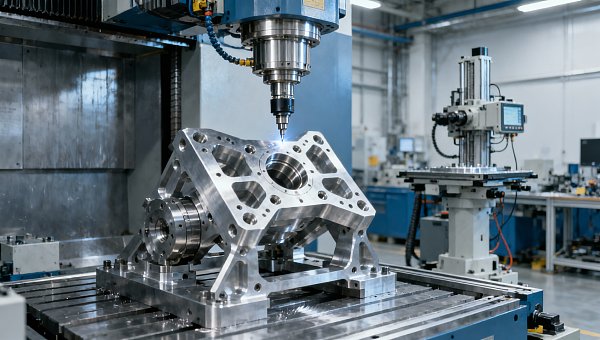
Why small CAD errors grow during CAM conversion
Publication Date
author
Even minor geometry gaps, tolerance mismatches, or layer errors in CAD can trigger costly issues once toolpaths are generated. In high-precision manufacturing, cad to cam conversion data loss is not a minor inconvenience—it can distort machining intent, affect cnc controller interpolation cycle stability, and undermine digital twin simulation accuracy. This article explains why small design flaws expand during CAM conversion and what engineers, operators, buyers, and decision-makers should verify before production risk escalates.
For R&D teams, the issue is not only whether a model looks complete on screen. The real question is whether the model survives translation into machining logic without losing design intent. For operators, that means fewer surprises at setup. For procurement teams, it means comparing suppliers on process maturity, not just quoted price. For business leaders, it means reducing scrap, rework, delivery delays, and qualification risk across the digital thread.
At TechStat Vanguard, the practical lesson is straightforward: parameters do not lie, and tolerances dictate success. CAD to CAM conversion sits exactly at that boundary where engineering truth is either preserved or diluted. Small upstream defects can become measurable downstream instability within 1 machining cycle, 1 fixture change, or 1 revision transfer. Understanding why this happens is essential in aerospace, robotics, medical parts, sensors, and any production environment where tolerance windows can shrink to ±0.01 mm or tighter.
Why tiny CAD defects become large CAM problems
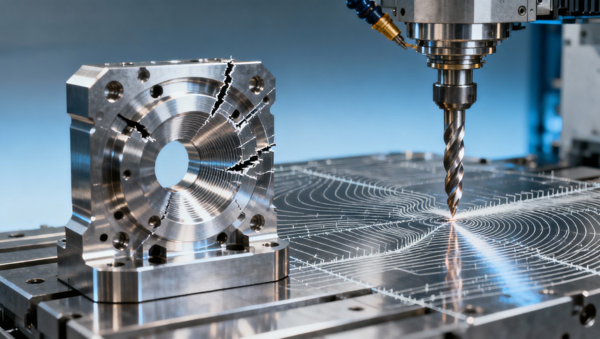
A CAD model is primarily a design representation, while a CAM system must interpret that representation as machine motion, cutting engagement, entry strategy, exit behavior, and controller-friendly toolpath logic. This is why a 0.02 mm surface gap that appears visually harmless in CAD can force CAM software to rebuild edges, split chains, or approximate curves into short segments. Once that happens, the final toolpath may no longer reflect the intended manufacturable surface.
The problem grows because conversion is rarely a 1-step process. In many shops, geometry moves through 3 to 5 layers: native CAD, neutral export such as STEP or IGES, CAM import, post-processing, and machine controller execution. Each stage can reinterpret splines, face normals, hole definitions, and tolerances. A mismatch introduced in stage 1 may remain invisible until stage 4, when feedrate behavior, tool engagement, or interpolation smoothness begins to degrade.
Another reason errors amplify is scale. A single broken contour on one feature may affect 20 to 200 lines of generated motion, depending on the strategy used. In 3-axis contouring, the effect may appear as extra retracts or missed edges. In 5-axis machining, the same defect can alter tool axis orientation, collision margins, and surface finish consistency. What looked like a drafting issue becomes a process capability issue.
This amplification is especially serious when shops rely on digital twin validation. If the CAD model, CAM environment, and controller post are not semantically aligned, simulation may confirm a path that still behaves differently on the machine. A digital twin is only as accurate as the source geometry and conversion rules behind it. Even a 1-degree normal inconsistency or an open edge chain can undermine confidence in virtual verification.
Common geometry defects that escalate after conversion
The table below outlines several small CAD issues that often appear manageable in design review but become disproportionately expensive once the CAM workflow begins.
The important takeaway is that the numerical size of the original error does not predict the financial size of the downstream problem. A defect under 0.05 mm can still cause hours of programming rework, unstable cycle behavior, or a failed first article inspection if it lands on a critical surface, blend region, or datum-related feature.
Where conversion data loss really happens in the workflow
Many teams assume the CAD file itself is the single source of truth. In practice, the most common losses happen during translation between software kernels, neutral formats, and post-processing rules. STEP is generally more robust than IGES for solid model transfer, but even STEP workflows can lose feature intelligence, layer intent, color coding, or PMI associations depending on software version and export settings. This matters when the CAM operator depends on semantic clues to select machining strategy.
A second failure point appears when feature-based machining tries to auto-detect holes, pockets, slots, and planar regions. If the original model contains tiny overlaps, sliver faces, duplicate edges, or non-manifold geometry, automatic recognition may misclassify features or ignore them completely. That often forces manual programming, increasing lead time by 10% to 30% on complex part families. In low-volume, high-mix production, those hours directly affect quotation accuracy and machine utilization.
The post-processor is another weak link. Even with clean geometry, output can degrade when arc fitting, smoothing settings, tolerance compression, or controller-specific syntax are poorly matched to the machine. A toolpath that simulates well in CAM may become segmented G-code that overwhelms controller look-ahead buffers. On some controllers, that can reduce surface finish quality or produce feedrate oscillation in high-speed finishing, especially when short linear moves fall below stable interpolation thresholds.
Finally, there is organizational data loss. Design teams may model to one tolerance logic, CAM teams may program to another, and suppliers may inspect to a third interpretation. If revision control is weak, a part can pass through 2 or 3 departments before someone notices that the machining datum, stock allowance, or chamfer convention changed. By then, the issue is no longer digital. It has become purchased material, machine time, and delivery risk.
High-risk handoff points to audit
- Native CAD to neutral export: verify whether solids remain watertight and whether model tolerance remains consistent within 0.001-0.01 mm expectations.
- Neutral import to CAM: check for missing surfaces, duplicate entities, flipped normals, and degraded spline continuity before programming begins.
- CAM to post-processing: confirm smoothing, arc output, segmentation limits, and controller compatibility for 3-axis or 5-axis motion.
- Post to machine: validate look-ahead behavior, block processing capability, and interpolation settings on the target CNC controller.
- Design revision to shop release: ensure the active revision, fixture strategy, and inspection datum scheme all match the same release package.
For procurement and leadership teams, these handoff points are useful supplier audit checkpoints. A vendor that cannot explain its CAD healing thresholds, import validation method, or post-processor verification routine is not simply lacking software detail. It may be exposing your project to hidden conversion risk.
Operational signs that data loss is already affecting production
Shops often notice symptoms before they identify the cause. Repeated tool re-entry, unexpectedly large NC files, inconsistent rest machining, air cutting, and simulation-to-machine mismatch are all warning signs. If first-pass yield drops below the expected range, or if programmers keep repairing the same imported geometry manually, the CAD to CAM chain needs review before throughput suffers further.
How small errors affect machining accuracy, controller behavior, and simulation
Once toolpaths are generated, geometry defects can influence three performance layers at the same time: part accuracy, machine dynamics, and digital verification reliability. On the accuracy side, edge ambiguity may shift cutter compensation logic, corner blending, or rest-material assumptions. That may create leftover stock in one region and overcut risk in another. On precision parts, a few microns of interpretation drift can matter if multiple surfaces stack into a critical assembly tolerance chain.
On the controller side, fragmented geometry often turns smooth motion into thousands of short segments. A controller with finite look-ahead capacity may respond by decelerating repeatedly. If the commanded feed is 6,000 mm/min but the actual path contains dense micro-segments, real feed may drop far below target. The result is not only longer cycle time but also thermal inconsistency, tool wear pattern changes, and visibly uneven finish on sculpted surfaces.
Simulation accuracy also suffers when source geometry is weak. A digital twin can only evaluate collisions, engagement, and timing based on the data fed into it. If stock models, surface offsets, and machine kinematics are built on slightly corrupted geometry, simulation may underpredict gouge risk or overestimate path smoothness. This is particularly risky in aerospace brackets, UAV structural parts, sensor housings, and precision medical components where verification needs to be conservative, not optimistic.
The business impact is cumulative. A single import defect may add 15 minutes of manual cleanup. Across 40 parts per month, that becomes 10 hours or more of non-value-added engineering time. If one of those parts also fails inspection or requires remachining, the cost expands again through setup repetition, scheduling disruption, and delayed shipment. What began as a geometric inconsistency ends as a measurable commercial penalty.
Typical downstream effects by manufacturing stage
The following table helps different stakeholders connect upstream model quality with downstream operational outcomes.
The pattern is clear: conversion problems do not remain confined to software. They affect programming efficiency, CNC controller interpolation cycle stability, and the credibility of the verification process itself. Teams that measure only final dimensional results often discover the issue too late. Teams that monitor data quality earlier prevent cost multiplication.
What engineers, operators, buyers, and decision-makers should verify before release
Different stakeholders need different checkpoints, but the goal is the same: preserve design intent through the full digital manufacturing chain. Engineers should confirm that the model is watertight, that critical surfaces carry consistent normal orientation, and that export tolerance aligns with machining requirements. For many precision parts, practical review thresholds fall around 0.001-0.01 mm depending on process capability and feature sensitivity. The exact number varies, but undefined tolerance transfer should never be accepted.
Operators need visibility into what was repaired or approximated during import. If a CAM file has been healed, split, or simplified, setup personnel should know which regions are most sensitive. That supports better prove-out, safer feed overrides, and more focused first-piece checks. A 5-minute handoff discussion between programming and the machine can prevent a 2-hour recovery after an avoidable path issue.
Buyers should evaluate supplier maturity beyond software brand names. Ask whether the supplier validates neutral file imports, documents geometry repair steps, and tests post output on the target controller family. Also ask how often first article corrections trace back to CAD to CAM conversion rather than machine capability. A lower quote is less attractive if hidden translation errors create schedule slippage 2 weeks later.
Executives and program leaders should treat digital manufacturability as a risk control function. When parts are complex, low-volume, or certification-sensitive, an early review gate can save significant time. In many organizations, adding a structured pre-CAM validation step of 20 to 40 minutes per part family is more economical than absorbing repeated rework across design, programming, machining, and inspection.
A practical verification checklist
- Confirm model integrity: check open edges, duplicate surfaces, sliver faces, and non-manifold geometry before export.
- Align tolerance strategy: define modeling tolerance, export tolerance, CAM import tolerance, and toolpath tolerance as an intentional chain.
- Validate semantic information: verify layers, colors, PMI, datum references, and feature naming if downstream teams depend on them.
- Review controller compatibility: compare toolpath segmentation, arc usage, smoothing, and look-ahead requirements with actual machine capability.
- Run simulation with skepticism: use digital twin results as decision support only after source geometry quality is confirmed.
- Document healing actions: record every geometry repair that could alter intent, especially on sealing faces, aerodynamic contours, and fit-critical features.
Questions procurement teams should ask suppliers
Useful questions include: Which neutral formats are preferred and why? What is the standard review time for imported geometry? How are geometry repairs approved? What controller families have been validated for high-segment toolpaths? What is the process when simulation and machine behavior differ? These questions reveal whether the supplier manages engineering truth through data or relies on manual correction after problems appear.
Best practices to reduce CAD to CAM conversion risk across the supply chain
The most effective strategy is not a single software feature but a disciplined process. Start by standardizing file exchange rules by part class. For example, 2.5D plate components, freeform mold surfaces, and 5-axis aerospace parts should not all follow the same export assumptions. Different geometries justify different format preferences, tolerance settings, and validation depth. A controlled rule set improves consistency across internal teams and external suppliers.
Second, define a pre-CAM quality gate. This can be lightweight but must be repeatable. A good gate checks at least 4 areas: topology integrity, tolerance alignment, feature readability, and machining relevance. If a model fails any one of these, teams should repair or re-export before programming begins. This is particularly valuable in multi-site manufacturing where design may happen in one region, CAM in another, and machining in a third.
Third, build controller-aware programming standards. CAM output should not be judged only by visual smoothness in software. It should be evaluated by how the specific machine interprets arcs, splines, and short moves. For high-speed finishing, test whether the controller maintains stable feed on dense geometry. For precision bores and critical blends, verify whether post settings preserve path intent within acceptable tolerance bands such as ±0.005 mm, ±0.01 mm, or the range appropriate to the part.
Fourth, create traceability between design changes and shop-floor execution. If a revised model modifies one fillet chain, one datum, or one hidden surface patch, that should be visible to CAM, inspection, and production planning. Without digital traceability, small geometry edits can continue to generate old assumptions in toolpath strategy, fixture planning, or measurement routines. That is how avoidable conversion defects survive into released production.
Recommended control framework
For organizations sourcing globally, these controls also improve supplier comparability. A supplier that can document geometry validation, post verification, and revision traceability is easier to qualify than one that promises quality without measurable process checkpoints. That distinction matters when selecting partners for aerospace, automation, edge AI hardware, and other advanced manufacturing programs where tolerance discipline is strategic, not optional.
FAQ
How small is “small” in CAD error terms?
In many workflows, gaps of 0.01-0.05 mm, tiny sliver surfaces, or slight normal inconsistencies can still create major CAM complications. The risk depends less on raw size and more on location, geometry type, and the downstream strategy being used.
Is STEP always safer than IGES for CAD to CAM conversion?
Often yes for solid model integrity, but not universally. The right choice depends on the CAD kernel, surface complexity, and whether semantic information needs to survive transfer. Teams should validate actual import outcomes instead of relying on format reputation alone.
Who should own conversion quality: design or manufacturing?
Both. Design owns source integrity and intent clarity. Manufacturing owns import validation, toolpath feasibility, and controller-aware execution. The strongest organizations formalize shared checkpoints rather than leaving the burden to one department.
When should buyers treat conversion risk as a supplier selection issue?
Any time the part involves tight tolerance chains, freeform surfaces, multi-axis machining, or costly materials. In these cases, digital translation quality can have as much impact on delivery and cost as spindle capability or hourly rate.
Small CAD errors grow during CAM conversion because each translation step transforms design geometry into manufacturing decisions. If the geometry is incomplete, ambiguous, or tolerance-misaligned, the error expands through programming, post-processing, controller execution, and inspection. For engineers, the solution is disciplined model integrity and tolerance control. For operators, it is visibility into repaired or risky geometry. For buyers and decision-makers, it is supplier selection based on measurable digital process capability.
TechStat Vanguard focuses on the hard-tech reality behind manufacturing claims: exact thresholds, practical validation steps, and benchmark-driven risk awareness. If your team is evaluating machining partners, refining CAD to CAM workflows, or building a more reliable digital manufacturing chain, now is the time to review the data path before production risk compounds. Contact us to discuss your application, request a tailored assessment framework, or explore more data-driven solutions for precision manufacturing decisions.
Search News
Hot Articles
- Carbon Fiber StructuresHow to Specify Aerospace Carbon Fiber Assemblies for Lightweight, Load-Bearing PartsJul 11, 2026
- Machine VisionXiaomi, Alibaba DAMO Academy Drive Open-Source Robotics Model Ecosystem, Lowering Algorithm Development Barriers for Overseas SMEs Adopting Chinese Robotics SolutionsMar 30, 2026
- Cobots & ArmsShanxi 'AI+' Conference Showcases Embodied Intelligence with Multinational Buyer Engagement: Key Industry ImplicationsMar 30, 2026
Popular Tags
Recommended News
 Jul 11, 2026How to Specify Aerospace Carbon Fiber Assemblies for Lightweight, Load-Bearing PartsAerospace carbon fiber assemblies: learn how to specify laminate design, load data, joining methods, and inspection controls for lighter, reliable load-bearing aerospace parts.Elena Rostova (UAV Systems Researcher)
 Mar 30, 2026Xiaomi, Alibaba DAMO Academy Drive Open-Source Robotics Model Ecosystem, Lowering Algorithm Development Barriers for Overseas SMEs Adopting Chinese Robotics SolutionsXiaomi & Alibaba DAMO Academy's open-source robotics models lower algorithm barriers for global SMEs. Boost efficiency in manufacturing, logistics & smart retail with ROS 2 compatible solutions.TSV Data Lab
 Mar 30, 2026Shanxi 'AI+' Conference Showcases Embodied Intelligence with Multinational Buyer Engagement: Key Industry ImplicationsShanxi 'AI+' Conference highlights embodied intelligence with Tesla, Ubtech & Jiantao showcasing multimodal robotics. 40+ global buyers validated tech on-site, creating new B2B channels for industrial automation & AI solutions.Chen Wei (Automation Lead Engineer)
 Mar 30, 2026Zhongguancun Unveils 6G Integrated Sensing-Computing-Intelligence Platform to Empower Embodied Robots for Global Industrial ApplicationsZhongguancun's new 6G platform revolutionizes industrial robotics with <10ms latency, empowering global automotive, logistics & port automation. Discover how this tech boosts China's smart manufacturing exports.TSV Data Lab
 Mar 30, 2026Mech-Mind Tianjin Embodied Intelligence R&D and Production Base Goes Live, Cutting Delivery Time by 20%–30% for Global Customized AMR+Vision SolutionsMech-Mind's Tianjin AMR+Vision production base cuts delivery time by 20%-30% for欧美 & Latin American markets. Discover how this PLd-certified facility accelerates customized robotics solutions for smart manufacturing and logistics.Chen Wei (Automation Lead Engineer)
 Mar 30, 2026Boao Forum Reveals 'Co-evolution of Big and Small Brains' Trend in Humanoid Robots, China's Embodied Intelligence Accelerates Adaptation to Overseas Manufacturing Service ScenariosDiscover how China's humanoid robots, featuring 'Co-evolution of Big and Small Brains,' are revolutionizing global manufacturing. Learn about Embodied Tian Gong 3.0's ISO compliance and overseas deployment at Boao Forum 2026.Chen Wei (Automation Lead Engineer)
 Mar 30, 2026China Railway Industrial Secures Patent for Embodied Robotics in Material Handling, Boosting High-Precision Delivery Capabilities for Overseas Infrastructure and Manufacturing ProjectsChina Railway Industrial's new patent for embodied robotics in material handling boosts high-precision delivery for global infrastructure & manufacturing. Discover how this innovation enhances logistics accuracy in automotive, rail transit & EPC projects.Chen Wei (Automation Lead Engineer)
 Oct 15, 2026R&D Cost Reduction Services: How to Evaluate Fees, Savings, and ROIEvaluate R&D cost reduction services with confidence. Compare fees, verify savings, and calculate ROI without compromising performance. Discover how to choose a provider that delivers real value.Chen Wei (Automation Lead Engineer)
 Oct 15, 2026How Should You Compare TechStat Vanguard 5-Axis CNC Tolerances?TechStat Vanguard 5-axis CNC tolerance comparison: learn how to verify part accuracy, assess inspection evidence, and choose suppliers that reliably meet your drawing requirements.Dr. Marcus Vance
 Oct 14, 2026Drone Frame Composites: Carbon Fiber vs. Fiberglass for Weight and StiffnessExplore drone structural materials composites: compare carbon fiber and fiberglass for weight, stiffness, cost, and antenna compatibility. Find the right material for your drone frame.Elena Rostova (UAV Systems Researcher)
 Oct 13, 2026Smart Cameras vs. PC-Based Machine Vision: Which Fits High-Speed Inspection?This industrial product comparison for machine vision weighs smart cameras vs. PC-based systems on latency, throughput, and cost. Discover your best fit for high-speed inspection.TSV Data Lab
 Oct 12, 2026How to Verify RoHS Compliance in Industrial Sensing Systems Before DeploymentRoHS compliant sensing systems: learn how to verify materials, supplier declarations, testing, and configuration controls before industrial deployment.TSV Data Lab
 Oct 11, 2026How Procurement-Oriented Content Taxonomy Improves B2B Buying JourneysProcurement-oriented content taxonomy streamlines B2B buying journeys with clearer evidence, supplier comparisons, risk visibility, and faster approvals.TSV Data Lab
 Oct 10, 2026How to Select a Machine Performance Monitoring Platform for OEE and Downtime ReductionMachine performance monitoring platform selection guide: validate machine states, OEE data, downtime reasons, integrations, and scalability to reduce losses with confidence.TSV Data Lab
 Oct 08, 2026How to Machine Inconel 625 Blades Without Heat Cracks or Edge ChippingInconel 625 blade machining guide: prevent heat cracks, edge chipping, chatter, and work hardening with proven tooling, cooling, fixturing, and inspection strategies.Dr. Marcus Vance
 Oct 07, 2026How to Evaluate an HMI Panel Distributor for Industrial Automation ProjectsHMI panel distributor evaluation guide: verify technical compatibility, traceability, supply reliability, lifecycle support, and total cost for automation projects.Victor Lin (Chief Software Architect)
 Oct 06, 2026Navigation Fault Tolerance Standards for AMRs: What Safety Teams Must VerifyNavigation fault tolerance standards: learn what AMR safety teams must verify, from localization loss and sensor faults to stopping distance, safe restart, and site-specific validation.Chen Wei (Automation Lead Engineer)
 Oct 05, 2026Calculating Edge Computing Total Cost of Ownership Across Distributed SitesEdge computing ownership cost explained: calculate deployment, energy, connectivity, security, remote support, and refresh costs across distributed sites.TSV Data Lab
 Oct 04, 2026CAD/CAM Benchmarking in the GCC: What Manufacturers Should Ask a ConsultantCAD CAM benchmark consultant GCC guide: learn the key questions manufacturers should ask to validate post-processors, workflows, machine performance, and production risk.Victor Lin (Chief Software Architect)
 Oct 03, 2026Selecting Automotive Radar Sensor Modules for ADAS Range, Resolution, and IntegrationAutomotive radar sensor module selection guide for ADAS: compare range, resolution, field of view, latency, and integration to build safer, reliable vehicle systems.TSV Data Lab
 Oct 02, 2026How to Qualify Machined Parts Suppliers for Hard Tech ProgramsHard tech supply chain machined parts demand rigorous supplier qualification. Learn how to assess capability, traceability, quality controls, and delivery resilience.Dr. Marcus Vance
 Oct 01, 2026How to Select an Outdoor Security Radar Sensor for Perimeter Detection?Outdoor security radar sensor selection guide: compare range, accuracy, false-alarm control, integration, and field testing for reliable perimeter detection.TSV Data Lab
 Sep 30, 2026How to Evaluate Solid-State LiDAR Hardware for Outdoor Autonomous VehiclesSolid state LiDAR hardware evaluation guide for outdoor autonomous vehicles—compare range, point-cloud quality, environmental resilience, integration, and safety.TSV Data Lab
 Sep 29, 2026ISO 9283 Repeatability: How to Evaluate Cobot Positioning PerformanceISO 9283 cobot repeatability explained: learn how payload, reach, approach direction, and test conditions affect positioning performance and cell capability.Chen Wei (Automation Lead Engineer)