
Where CAD to CAM Conversion Data Loss Usually Begins
Publication Date
author
In precision manufacturing, cad to cam conversion data loss rarely starts at the machine—it usually begins upstream, when design intent is weakened by loose modeling practices, incomplete metadata, or incompatible file translation. For operators and production teams, understanding where these gaps first appear is essential to protecting tolerances, toolpaths, and part quality before costly errors reach the shop floor.
Why cad to cam conversion data loss starts earlier than most operators expect
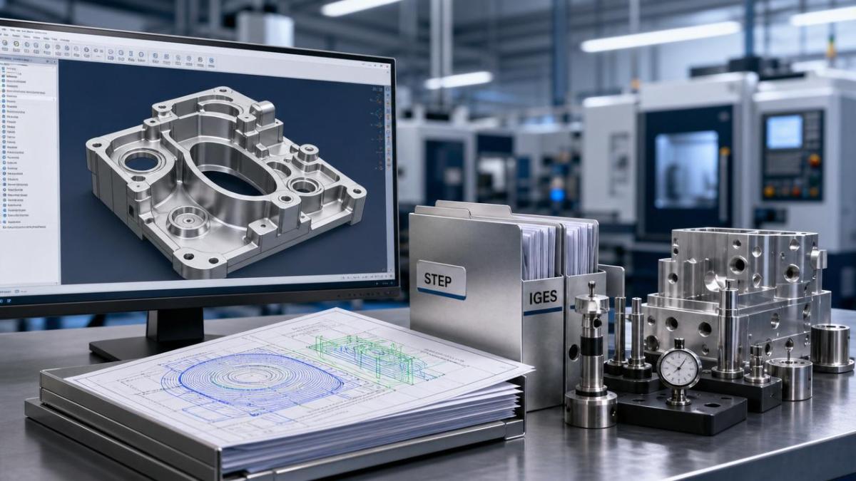
Many users assume the first serious error appears when a CNC program runs incorrectly, a feature gouges, or a setup dimension fails inspection. In practice, cad to cam conversion data loss often begins much earlier, during model creation, export preparation, or digital handoff between engineering and production.
This matters across industries because modern production depends on a chain of software interpretation. A geometry decision made in design can affect feature recognition in CAM. A missing note can change machining strategy. An incomplete tolerance callout can force an operator to guess intent under time pressure.
For TSV, the issue is not marketing language or vague claims about seamless interoperability. The real question is measurable: what exact design information survives the transition, what information degrades, and what hidden losses increase scrap, rework, or cycle time?
- Geometry may transfer, but surface continuity, feature hierarchy, and parametric intent may not.
- Dimensions may appear visually correct, yet tolerance context, datum structure, or material notes may be absent.
- Toolpath generation may still complete, but feeds, entry strategies, stock assumptions, or collision margins may be based on incomplete data.
Operators are usually the last line of defense. When upstream data weakens, they absorb the risk through manual edits, workarounds, and extra verification. That is why reducing cad to cam conversion data loss is not only an engineering concern. It is a shop-floor control issue.
Where data loss usually begins in the CAD model itself
The earliest source of cad to cam conversion data loss is often the modeling method. Even before export, poor model discipline can break downstream interpretation. CAM systems rely on clean geometry, consistent feature boundaries, and usable references. When those elements are weak, conversion becomes unstable.
Common upstream modeling issues
- Imported or patched surfaces with tiny gaps can prevent reliable feature detection for pockets, holes, or fillets.
- Overcomplicated sketches and unstable feature trees may cause export differences after model revision.
- Unclear layer naming, suppressed features, or construction geometry left active can confuse manufacturing preparation.
- Mixed units, especially inch-to-millimeter handoffs, can create scaling errors that survive unnoticed until setup or inspection.
These are not minor drafting imperfections. In high-precision machining, especially where aerospace, medical, automation, or sensor housings are involved, small geometry inconsistencies can alter stock recognition, clamp clearance, or finishing path quality.
TSV’s data-first view is simple: if model topology is unstable, downstream software will not restore intent. Operators should therefore ask not only whether the file opens, but whether the model remains machinable without reinterpretation.
Which design information is most vulnerable during CAD to CAM translation
Not all data is equally fragile. Solid shape usually transfers more easily than manufacturing intelligence. The most damaging cad to cam conversion data loss often involves the information that tells the machine shop how to think, not just what to cut.
The table below shows which data categories commonly degrade during translation and how that affects operators and users on the production side.
The practical lesson is clear: if only the visible shape transfers, the job may still be at risk. Operators should verify manufacturing-critical intent separately instead of assuming the file package is complete because the model looks correct on screen.
What file formats and workflows increase cad to cam conversion data loss risk
Conversion risk often depends on workflow choice. Native file exchange may preserve more intelligence, but only when both systems support compatible versions and feature mapping. Neutral formats improve accessibility, yet they often sacrifice semantic richness.
Comparison of common transfer approaches
For teams comparing options, this table helps identify where cad to cam conversion data loss is more likely and where extra checks are required before programming begins.
No format is automatically safe. The best workflow is the one that preserves the highest amount of useful manufacturing data while minimizing ambiguity. For many teams, that means combining a robust 3D exchange method with controlled revision management and explicit verification steps.
How operators can catch conversion problems before machining starts
Operators and programmers do not need to rebuild the whole digital thread to reduce risk. They need a repeatable pre-machining check that exposes cad to cam conversion data loss before material, spindle time, and delivery schedules are affected.
A practical verification checklist
- Confirm unit integrity by checking at least three known dimensions against the released drawing or specification sheet.
- Inspect hole sizes, thread definitions, chamfers, and fillets that commonly break during translation or feature recognition.
- Verify datum references, critical faces, and stock orientation before building setup sheets or fixture plans.
- Check whether surface continuity supports the intended finishing strategy, especially on 3D contours and sealing surfaces.
- Review material, hardness, coating, and finish notes in the source package, not only inside the imported model.
- Run simulation with collision review after confirming stock, work offsets, and tool assembly assumptions match the job packet.
This process is especially important when operators inherit work from external design teams, overseas suppliers, or mixed software environments. The more fragmented the handoff, the greater the chance that hidden conversion gaps will reach the machine.
What purchasing and production teams should ask suppliers before accepting digital files
Cad to cam conversion data loss is not only a technical event. It is also a supplier qualification issue. If production teams accept unclear file packages, they inherit hidden risk that later appears as programming delays, NCRs, or delivery misses.
Before awarding work or approving a manufacturing partner, teams should ask targeted questions about digital readiness, version control, and process discipline.
- Which CAD and CAM systems are used, and how often are file compatibility issues encountered between customer data and internal workflow?
- What neutral formats are preferred for backup exchange, and what information is known to be lost during translation?
- How are revisions controlled so that operators, programmers, and inspectors work from one released source?
- Is there a documented import verification step before toolpath release and first article production?
- How are PMI, GD&T, finish notes, and special process requirements communicated when native interoperability is limited?
TSV’s benchmarking philosophy supports this approach. Procurement should evaluate measurable transfer reliability, not vague promises of digital integration. A supplier that can explain its verification logic clearly is often safer than one that only claims compatibility.
How standards, documentation, and process discipline reduce hidden losses
In regulated or high-precision sectors, informal handoff habits are rarely enough. Strong documentation reduces cad to cam conversion data loss by making engineering intent visible beyond a single software environment. That is why disciplined teams rely on structured release packages, not just model transmission.
Documentation elements worth standardizing
- Revision-controlled model and drawing packages with one clear authority source.
- Explicit material, finish, and special process notes tied to the released part definition.
- Datum schemes and critical-to-function characteristics visible to programming and inspection teams.
- Import validation records for complex 3D surfaces, multi-axis parts, and tolerance-sensitive features.
Where applicable, practices aligned with quality systems such as AS9100 or ISO 13485 can reinforce traceability, document control, and process verification. These standards do not eliminate software translation problems by themselves, but they create stronger conditions for early detection and accountability.
FAQ: practical questions about cad to cam conversion data loss
Is cad to cam conversion data loss mainly a software problem?
No. Software compatibility is one factor, but weak modeling habits, missing metadata, poor revision control, and unclear manufacturing notes are often bigger causes. Better software cannot fully recover design intent that was never structured clearly in the first place.
Which parts are most sensitive to conversion loss?
Parts with complex surfacing, tight GD&T, multi-axis machining, thin walls, sealing features, or critical finish requirements are especially vulnerable. These jobs depend on more than shape alone. They require preserved intent, setup logic, and process notes.
Can a good simulation catch everything?
Simulation is valuable, but it only tests the assumptions inside the CAM environment. If the imported model already lost datum logic, finish requirements, or true feature meaning, simulation may confirm a program that is still wrong for the released design intent.
What is the fastest way to reduce risk on mixed-software jobs?
Use a controlled exchange package, verify critical dimensions and notes before programming, and define one approved revision source. For recurring suppliers, establish a fixed import checklist and review the same failure points on every job until translation performance becomes predictable.
Why choose us for data-driven evaluation and next-step support
TSV approaches cad to cam conversion data loss the same way we approach hard-tech benchmarking in robotics, aerospace, sensors, and precision machining: by filtering out vague claims and focusing on parameters, transfer reliability, and operational consequences.
If your team is comparing suppliers, reviewing a file-transfer workflow, or trying to reduce programming ambiguity, you can engage with TSV around concrete decision points rather than generic sales language.
- Parameter confirmation for model handoff, tolerance visibility, and metadata completeness.
- Supplier evaluation support for digital workflow discipline, traceability, and machining readiness.
- Selection guidance for transfer methods, verification checkpoints, and documentation structure.
- Discussion on delivery risk, sample review logic, revision control expectations, and certification-related documentation needs.
If you need a clearer basis for file acceptance, process comparison, or supplier communication, contact TSV with your conversion scenario, part type, tolerance concerns, and workflow constraints. We help engineering and production teams move from assumption to evidence—because parameters do not lie, and tolerances still decide the outcome.
Search News
Hot Articles
- Carbon Fiber StructuresHow to Specify Aerospace Carbon Fiber Assemblies for Lightweight, Load-Bearing PartsJul 11, 2026
- Machine VisionXiaomi, Alibaba DAMO Academy Drive Open-Source Robotics Model Ecosystem, Lowering Algorithm Development Barriers for Overseas SMEs Adopting Chinese Robotics SolutionsMar 30, 2026
- Cobots & ArmsShanxi 'AI+' Conference Showcases Embodied Intelligence with Multinational Buyer Engagement: Key Industry ImplicationsMar 30, 2026
Popular Tags
Recommended News
 Jul 11, 2026How to Specify Aerospace Carbon Fiber Assemblies for Lightweight, Load-Bearing PartsAerospace carbon fiber assemblies: learn how to specify laminate design, load data, joining methods, and inspection controls for lighter, reliable load-bearing aerospace parts.Elena Rostova (UAV Systems Researcher)
 Mar 30, 2026Xiaomi, Alibaba DAMO Academy Drive Open-Source Robotics Model Ecosystem, Lowering Algorithm Development Barriers for Overseas SMEs Adopting Chinese Robotics SolutionsXiaomi & Alibaba DAMO Academy's open-source robotics models lower algorithm barriers for global SMEs. Boost efficiency in manufacturing, logistics & smart retail with ROS 2 compatible solutions.TSV Data Lab
 Mar 30, 2026Shanxi 'AI+' Conference Showcases Embodied Intelligence with Multinational Buyer Engagement: Key Industry ImplicationsShanxi 'AI+' Conference highlights embodied intelligence with Tesla, Ubtech & Jiantao showcasing multimodal robotics. 40+ global buyers validated tech on-site, creating new B2B channels for industrial automation & AI solutions.Chen Wei (Automation Lead Engineer)
 Mar 30, 2026Zhongguancun Unveils 6G Integrated Sensing-Computing-Intelligence Platform to Empower Embodied Robots for Global Industrial ApplicationsZhongguancun's new 6G platform revolutionizes industrial robotics with <10ms latency, empowering global automotive, logistics & port automation. Discover how this tech boosts China's smart manufacturing exports.TSV Data Lab
 Mar 30, 2026Mech-Mind Tianjin Embodied Intelligence R&D and Production Base Goes Live, Cutting Delivery Time by 20%–30% for Global Customized AMR+Vision SolutionsMech-Mind's Tianjin AMR+Vision production base cuts delivery time by 20%-30% for欧美 & Latin American markets. Discover how this PLd-certified facility accelerates customized robotics solutions for smart manufacturing and logistics.Chen Wei (Automation Lead Engineer)
 Mar 30, 2026Boao Forum Reveals 'Co-evolution of Big and Small Brains' Trend in Humanoid Robots, China's Embodied Intelligence Accelerates Adaptation to Overseas Manufacturing Service ScenariosDiscover how China's humanoid robots, featuring 'Co-evolution of Big and Small Brains,' are revolutionizing global manufacturing. Learn about Embodied Tian Gong 3.0's ISO compliance and overseas deployment at Boao Forum 2026.Chen Wei (Automation Lead Engineer)
 Mar 30, 2026China Railway Industrial Secures Patent for Embodied Robotics in Material Handling, Boosting High-Precision Delivery Capabilities for Overseas Infrastructure and Manufacturing ProjectsChina Railway Industrial's new patent for embodied robotics in material handling boosts high-precision delivery for global infrastructure & manufacturing. Discover how this innovation enhances logistics accuracy in automotive, rail transit & EPC projects.Chen Wei (Automation Lead Engineer)
 Sep 28, 2026Spindle Runout Measurement in Germany: DIN Standards, Methods, and Acceptance LimitsSpindle runout measurement Germany: explore DIN standards, proven methods, acceptance limits, and audit-ready practices for reliable machining quality.Dr. Marcus Vance
 Sep 27, 2026How to Select Wall-Mount Edge Devices for Space-Constrained Factory NetworksWall mount edge devices for space-constrained factories: evaluate workload, thermal design, power resilience, cable access, and network reliability for smarter deployments.TSV Data Lab
 Sep 26, 2026Machining Tolerance Analysis: How to Set Limits That Meet Function and Cost TargetsMachining tolerance analysis: learn how to set functional limits, control tolerance stacks, reduce inspection risk, and balance precision with production cost.Dr. Marcus Vance
 Sep 25, 2026How to Evaluate an Industrial Infrastructure Data Platform for Multi-Site OperationsIndustrial infrastructure data platform evaluation guide for multi-site operations: compare data quality, edge resilience, interoperability, governance, and scalable proof-of-value criteria.Victor Lin (Chief Software Architect)
 Sep 24, 2026How to Select Machine Vision Optics for Accurate Inspection at Different Working DistancesMachine vision optics selection guide for accurate inspection at every working distance. Compare FOV, pixel scale, DOF, distortion, lighting, and telecentric options.TSV Data Lab
 Sep 23, 2026How to Evaluate a Machine Vision System Integrator for High-Speed Inspection LinesChoose a machine vision system integrator with proven expertise in high-speed inspection, reliable reject timing, robust optics, and measurable acceptance criteria.TSV Data Lab
 Sep 28, 2026When is a SCADA API the right choice for connecting plant systems?SCADA API guide: learn when governed plant data integration improves traceability, security, and scalability—without compromising real-time control.Victor Lin (Chief Software Architect)
 Sep 27, 2026How SCADA data integration improves traceability across production linesSCADA data integration connects production-line data to improve traceability, accelerate quality investigations, and strengthen safety decisions.Victor Lin (Chief Software Architect)
 Sep 26, 2026What to define before starting SCADA integration planningSCADA integration planning starts with clear scope, control boundaries, data models, cybersecurity, and testing. Discover the definitions that reduce risk and costly rework.Victor Lin (Chief Software Architect)
 Sep 25, 2026How a smart factory with Industrial IoT reduces production blind spotsDiscover how a smart factory with Industrial IoT turns real-time machine, quality, and workflow data into actionable insights that reduce production blind spots and delivery risks.Victor Lin (Chief Software Architect)
 Sep 24, 2026When does Industrial IoT make smart manufacturing easier to scale?Smart manufacturing Industrial IoT scales when trusted data, interoperable systems, and secure workflows turn connected assets into measurable gains.TSV Data Lab
 Sep 23, 2026What drives ultra-precision machining cost at 1-micron tolerance?Ultra precision machining cost per part at 1 micron tolerance depends on process, material, metrology, and yield. Learn how to compare quotes confidently.Dr. Marcus Vance
 Sep 22, 2026Drone Engine-T550CC Applications: Build the UAV Power System Around the MissionAn application guide for Drone Engine-T550CC integration, covering payload planning, airframe matching, cooling, fuel, vibration, test procedures, documentation, and service preparation.Elena Rostova (UAV Systems Researcher)
 Sep 22, 2026How to Evaluate Industrial Edge Computing Vendors for Factory DeploymentIndustrial edge computing vendor evaluation guide for factories: compare latency, protocol fit, reliability, security, and lifecycle support before deployment.TSV Data Lab
 Sep 21, 2026Drone Payload Integration: Matching Power, Data, and Center of Gravity for Reliable FlightsDrone payload integration made practical: balance power, data, center of gravity, and endurance to build safer, more reliable mission-ready flights.Elena Rostova (UAV Systems Researcher)
 Sep 20, 2026Autonomous Navigation Pricing: Cost Drivers and Budget Benchmarks for AMR ProjectsAutonomous navigation price explained: compare AMR cost drivers, software, sensors, integration, safety, and lifecycle budgets to build a scalable project plan.Chen Wei (Automation Lead Engineer)
 Sep 19, 2026How to Scope Automation Integration Services for Multi-System Factory ProjectsAutomation integration services: learn how to scope multi-system factory projects with clear workflows, interface contracts, safety boundaries, and acceptance criteria.Victor Lin (Chief Software Architect)























