How to Select a Thermal Sensor for Mapping Drones in Surveying Projects
Publication Date
author
A thermal survey can fail long before the aircraft leaves the ground. A team may fly a site with a high-resolution payload, generate an attractive colorized mosaic, and still be unable to defend the temperature values, locate the intended defects, or align the thermal layer with the required mapping deliverable. The problem is usually not “insufficient thermal resolution” alone. It is a mismatch between the sensor, the target size, the environmental conditions, and the level of measurement confidence the project requires.
To select a mapping drone thermal sensor, start with the final decision the map must support. For qualitative screening, such as locating suspect roof areas, drainage anomalies, or likely heat-loss zones, a stable radiometric thermal camera with an appropriate lens may be sufficient. For repeatable inspections, change detection, or reports that rely on defensible surface-temperature values, thermal sensitivity, calibration behavior, emissivity control, atmospheric correction, and geospatial workflow compatibility become selection gates rather than secondary specifications.
Define the survey output before comparing cameras
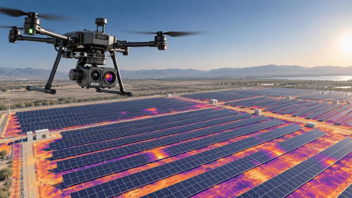
“Thermal mapping” can describe very different tasks. A broad-area solar survey needs enough ground resolution to isolate individual modules and identify meaningful temperature contrast. A building-envelope survey may need to distinguish a thermal bridge from a reflection caused by glazing or wet material. Water-management work may focus on relative patterns at the boundary between soil, vegetation, and shallow water rather than a precise absolute temperature.
Write the intended output in operational terms before reviewing sensor datasheets:
- Is the result a visual anomaly map, a temperature measurement layer, or both?
- What is the smallest target or defect that must be visible in the final map?
- Will a warm or cool feature be verified on the ground, or must the aerial result stand on its own?
- Is the comparison made within one flight, across seasons, or across repeated inspections?
- Must the thermal orthomosaic align with RGB imagery, LiDAR, CAD layers, or GIS asset records?
These questions prevent a frequent procurement error: selecting the highest advertised detector resolution even when the lens, flight altitude, or radiometric workflow prevents the camera from resolving the target reliably.
Separate detector resolution from usable ground detail
Detector resolution determines how many thermal pixels are available across the scene, but it does not by itself determine whether the target is identifiable. The lens field of view and flight geometry determine the ground sampling distance (GSD): the approximate area represented by each image pixel on the ground. A narrow lens can provide finer ground detail at the same altitude, while a wide lens captures more area but spreads each target across fewer pixels.
For survey planning, calculate expected thermal GSD at the proposed operating height, not simply at the payload’s maximum stated capability. Then consider the target in pixels, not only in physical dimensions. A feature that occupies one or two pixels may influence the color scale but cannot be reliably shaped, located, or separated from adjacent materials. A small hot connector, narrow crack, pipe edge, or individual solar-cell region often needs several pixels across its relevant dimension before it can be interpreted with confidence.
Lens choice also affects operational tolerance. A wide field of view can be more forgiving when terrain variation, obstacle clearance, or limited flight time constrains altitude. A narrow field of view can improve target definition but makes motion blur, attitude changes, and registration errors more apparent. The right balance is determined by the smallest decision-relevant feature, not by a preference for either wide-area coverage or maximum magnification.
Require radiometric data when measurement matters
Some thermal cameras produce imagery intended primarily for viewing: pixels are displayed as tones or colors, but the exported file does not retain calibrated temperature information for each pixel. Others are radiometric, meaning the sensor records thermal measurement data that can be interpreted later using parameters such as emissivity and reflected apparent temperature.
For simple reconnaissance, non-radiometric video can help direct field crews to unusual areas. It is usually a poor basis for a georeferenced temperature map because the analyst cannot revisit the raw measurement values or apply a consistent interpretation during post-processing. When the deliverable includes temperature values, thermal thresholds, or comparison between survey dates, select a fully radiometric payload and verify that its original measurement data is available to the software workflow.
Radiometric capability does not make every temperature value accurate by default. The camera measures infrared radiation reaching the detector, not the material’s temperature in isolation. Surface emissivity, reflectivity, viewing angle, distance, humidity, and atmospheric transmission can all affect the interpretation. A shiny roof, glass façade, wet metal surface, or solar module can reflect surrounding sky or sunlit objects, producing patterns that appear thermal but are not generated by the target itself.
Thermal sensitivity and accuracy answer different questions
Thermal sensitivity is commonly expressed as noise equivalent temperature difference (NETD). It indicates the camera’s ability to distinguish small differences in apparent temperature. Lower NETD generally helps reveal low-contrast patterns, which is useful when searching for subtle moisture effects, early-stage insulation issues, buried features, or gradual temperature changes across a surface.
Accuracy describes how closely reported temperatures correspond to actual conditions within stated limits. It matters when a project uses temperature thresholds or compares measurements collected on different dates. A sensor can have good sensitivity yet still require disciplined calibration and environmental input to support temperature-based decisions.
Evaluate both specifications in context. A project that only ranks warmer and cooler zones may value low noise and uniform image response more than absolute accuracy. A project that flags assets based on a defined temperature condition needs a documented approach to emissivity settings, reflected temperature, atmospheric inputs, and calibration checks. Avoid treating a single accuracy statement as valid under every target material and weather condition.
Assess calibration stability, not just factory specifications
Thermal detectors drift as their internal temperature changes. Many payloads use shutter-based non-uniformity correction to compensate for pixel-response variation. During a flight, this correction can briefly interrupt image capture or create variation between frames if the system is not operating consistently. This is not necessarily a defect; it is a characteristic that must be understood when mapping large areas.
Ask how the payload handles non-uniformity correction, warm-up, and radiometric stabilization. A sensor that performs well after an appropriate warm-up period may behave differently when launched immediately from a cold vehicle, operated through changing ambient conditions, or flown on multiple short sorties. Repeated map seams or inconsistent temperatures across overlapping image strips can result from calibration behavior, automatic gain changes, or unstable environmental inputs rather than true site variation.
Before accepting a workflow, run a controlled pre-survey check. Allow the payload to reach its recommended operating condition, image surfaces with known stable appearance, and inspect whether equivalent areas maintain a consistent response across frames. For projects requiring stronger temperature confidence, include suitable field reference targets and document the conditions under which the imagery was acquired. The purpose is not to create laboratory-grade calibration from a field flight; it is to identify whether the data are stable enough for the stated use.
Match the payload to the aircraft and mission geometry
A technically suitable camera can still be the wrong payload when its mass, power draw, mounting arrangement, or field of view disrupts the aircraft’s survey performance. Payload selection should include the drone as a measurement platform, not merely as transport.
Confirm the available payload capacity with batteries, mounting hardware, and any parallel payload such as an RGB camera. Check endurance under the expected takeoff weight, especially where a terrain-following route, crosswind, or repeated flight lines will increase power demand. Shorter endurance can force more sorties, creating more changes in light, ambient conditions, and overlap consistency.
Mounting geometry affects map quality. The sensor should have an unobstructed downward view and maintain a known orientation relative to the aircraft. Gimbal stabilization is valuable, but its behavior should be considered alongside trigger timing and aircraft attitude. A thermal image captured during yaw, pitch, or roll may still be usable, yet excessive angular variation complicates orthomosaic reconstruction and changes apparent radiation from reflective surfaces.
For multi-sensor mapping, determine whether the thermal and visible cameras are rigidly aligned, independently triggered, or mounted on separate flights. A shared payload assembly can simplify co-registration, but only when the processing system recognizes the sensor geometry and time relationship. Separate surveys can work, though ground control, flight planning, and site conditions must be managed more carefully.
Do not assume thermal images will stitch like RGB images
Photogrammetry software relies on identifiable features that appear across overlapping frames. Thermal imagery often has lower texture, lower contrast, and changing apparent values across materials. Uniform roofs, water surfaces, bare soil, and dense vegetation can be difficult to match, even when the flight plan provides conventional overlap.
Review the intended processing software before purchasing the camera. Confirm that it can ingest the sensor’s radiometric file format, preserve thermal values where needed, recognize the lens model, and export the required raster or GIS-compatible products. A visually pleasing thermal video format may be unsuitable for the mapping package used by the survey team.
Higher image overlap can improve reconstruction, but it is not a universal remedy. It increases capture time, storage requirements, and potentially the interval over which surface temperatures change. Use a flight plan that gives the processing workflow enough common features while keeping environmental change across the mission as limited as practical. Where thermal texture is weak, an accurately aligned RGB layer, surveyed ground control, or direct georeferencing may be needed to support positional reliability.
Check metadata and timing early
Every image must carry usable location and capture-time information. Verify that the system records coordinates, altitude references, orientation data where applicable, and time stamps in a form available to the processing chain. If the aircraft has RTK or PPK capability, determine whether the thermal camera exposure events are synchronized accurately enough to benefit from it. Positioning performance in the drone log does not automatically transfer to each thermal frame.
Also inspect export limitations. Some tools apply visual palettes, compression, or automatic contrast enhancement during export. Those outputs can be helpful for communication, but they should not replace the radiometric source data when analysts need to change emissivity assumptions, inspect individual pixels, or compare maps under a controlled color scale.
Plan for surface physics and weather, not just flight permission
The same sensor can produce useful results on one day and ambiguous results on another because thermal contrast depends on the target and the environment. Before buying a payload for a recurring program, identify the operating window that creates meaningful contrast. Building surfaces may need a particular heating or cooling cycle. Moisture-related anomalies can be masked after rain or confused by evaporative cooling. Wind can reduce or redistribute surface temperature differences. Direct sunlight can create reflections and localized heating unrelated to the defect being sought.
Viewing angle matters especially on reflective or low-emissivity materials. A nadir view is usually preferable for orthomosaic geometry, but it may not eliminate reflections from sky, sun, or nearby structures. Oblique imagery can sometimes help diagnose whether a pattern is a reflection, but it should be treated as complementary evidence rather than mixed indiscriminately into a nadir mapping dataset.
Build acquisition conditions into the sensor decision. A payload with low thermal noise and radiometric storage is more useful when the task requires subtle contrast, but no detector specification can compensate for a target whose thermal signature is absent or dominated by reflections.
A practical selection sequence for technical evaluation
- Set the decision threshold. Define whether the project needs anomaly detection, temperature measurement, repeatable trending, or legal-grade positional documentation.
- Translate target size into GSD. Select a lens and operating altitude that place the smallest relevant feature across enough pixels for the required interpretation.
- Choose radiometric capability deliberately. Use radiometric source data whenever temperatures, thresholds, or post-flight parameter adjustment matter.
- Review NETD, accuracy, and calibration behavior together. Favor low noise for subtle contrast; demand documented measurement discipline when absolute values drive decisions.
- Validate aircraft integration. Check payload mass, endurance, gimbal geometry, triggering, and sensor alignment under the actual planned configuration.
- Test the data path. Process representative files before committing to a payload, including raw import, orthomosaic generation, temperature handling, and GIS export.
- Run a limited field validation. Compare visible anomalies with field observations and inspect for seams, blur, inconsistent frames, or reflection artifacts.
The strongest thermal mapping setup is not necessarily the camera with the largest detector or the narrowest lens. It is the combination that resolves the target at a realistic altitude, records the required measurement data, stays stable through the planned mission, and produces files that remain interpretable after processing. When those conditions are specified first, sensor comparisons become engineering decisions rather than a comparison of headline specifications.
Search News
Hot Articles
- Carbon Fiber StructuresHow to Specify Aerospace Carbon Fiber Assemblies for Lightweight, Load-Bearing PartsJul 11, 2026
- Machine VisionXiaomi, Alibaba DAMO Academy Drive Open-Source Robotics Model Ecosystem, Lowering Algorithm Development Barriers for Overseas SMEs Adopting Chinese Robotics SolutionsMar 30, 2026
- Cobots & ArmsShanxi 'AI+' Conference Showcases Embodied Intelligence with Multinational Buyer Engagement: Key Industry ImplicationsMar 30, 2026
Popular Tags
Recommended News
 Jul 11, 2026How to Specify Aerospace Carbon Fiber Assemblies for Lightweight, Load-Bearing PartsAerospace carbon fiber assemblies: learn how to specify laminate design, load data, joining methods, and inspection controls for lighter, reliable load-bearing aerospace parts.Elena Rostova (UAV Systems Researcher)
 Mar 30, 2026Xiaomi, Alibaba DAMO Academy Drive Open-Source Robotics Model Ecosystem, Lowering Algorithm Development Barriers for Overseas SMEs Adopting Chinese Robotics SolutionsXiaomi & Alibaba DAMO Academy's open-source robotics models lower algorithm barriers for global SMEs. Boost efficiency in manufacturing, logistics & smart retail with ROS 2 compatible solutions.TSV Data Lab
 Mar 30, 2026Shanxi 'AI+' Conference Showcases Embodied Intelligence with Multinational Buyer Engagement: Key Industry ImplicationsShanxi 'AI+' Conference highlights embodied intelligence with Tesla, Ubtech & Jiantao showcasing multimodal robotics. 40+ global buyers validated tech on-site, creating new B2B channels for industrial automation & AI solutions.Chen Wei (Automation Lead Engineer)
 Mar 30, 2026Zhongguancun Unveils 6G Integrated Sensing-Computing-Intelligence Platform to Empower Embodied Robots for Global Industrial ApplicationsZhongguancun's new 6G platform revolutionizes industrial robotics with <10ms latency, empowering global automotive, logistics & port automation. Discover how this tech boosts China's smart manufacturing exports.TSV Data Lab
 Mar 30, 2026Mech-Mind Tianjin Embodied Intelligence R&D and Production Base Goes Live, Cutting Delivery Time by 20%–30% for Global Customized AMR+Vision SolutionsMech-Mind's Tianjin AMR+Vision production base cuts delivery time by 20%-30% for欧美 & Latin American markets. Discover how this PLd-certified facility accelerates customized robotics solutions for smart manufacturing and logistics.Chen Wei (Automation Lead Engineer)
 Mar 30, 2026Boao Forum Reveals 'Co-evolution of Big and Small Brains' Trend in Humanoid Robots, China's Embodied Intelligence Accelerates Adaptation to Overseas Manufacturing Service ScenariosDiscover how China's humanoid robots, featuring 'Co-evolution of Big and Small Brains,' are revolutionizing global manufacturing. Learn about Embodied Tian Gong 3.0's ISO compliance and overseas deployment at Boao Forum 2026.Chen Wei (Automation Lead Engineer)
 Mar 30, 2026China Railway Industrial Secures Patent for Embodied Robotics in Material Handling, Boosting High-Precision Delivery Capabilities for Overseas Infrastructure and Manufacturing ProjectsChina Railway Industrial's new patent for embodied robotics in material handling boosts high-precision delivery for global infrastructure & manufacturing. Discover how this innovation enhances logistics accuracy in automotive, rail transit & EPC projects.Chen Wei (Automation Lead Engineer)
 Oct 27, 2026GXO and Agility Robotics Expand Partnership to Accelerate US Humanoid Robot DeploymentGXO and Agility Robotics plan to expand US humanoid robot deployment with Digit 4 in early 2027. Explore warehouse automation plans, service terms and future Digit 5 upgrades.Chen Wei (Automation Lead Engineer)
 Oct 27, 2026Robotic Automation Costs: Budgeting for Equipment, Integration, and MaintenancePlan your robotics automation cost with confidence. Explore equipment, integration, and maintenance expenses, compare quotes, and build a realistic budget for better ROI.Chen Wei (Automation Lead Engineer)
 Oct 26, 2026AMAXiMAL Releases Open-Source TopMod 3D v3 With Claude AIExplore AMAXiMAL’s free, open-source TopMod 3D v3 with Claude AI assistance, topology-based modeling and plywood fabrication tools that connect complex designs to physical builds.Dr. Marcus Vance
 Oct 26, 2026Choosing a SCADA System Integrator Company: PLC Compatibility and Long-Term SupportChoose a scada system integrator company with proven PLC compatibility and reliable long-term support. Discover what to test, compare, and require before investing.Victor Lin (Chief Software Architect)
 Oct 25, 2026Hesai Leads Global ADAS Main Lidar Shipments in Yole’s 2026 ReportHesai led global ADAS main lidar shipments with a 43% share in 2025, according to Yole’s 2026 report. Explore what this ranking reveals about its automotive market position.TSV Data Lab
 Oct 25, 2026Choosing an Aerospace Materials Manufacturer: Quality and Traceability ChecksChoosing an aerospace materials manufacturer? Learn how to verify certifications, test reports, and lot traceability to qualify suppliers confidently and reduce costly sourcing risks.Dr. Marcus Vance
 Oct 24, 2026Guotai Haitong: Global Entry-Level 3D Printer Shipments Rose 39% in Q1 2026Entry-level 3D printer shipments rose 39% in Q1 2026, Guotai Haitong reports. Explore how AI, multicolor printing and print farms are shaping market growth.Dr. Marcus Vance
 Oct 24, 2026Choosing an Industrial Vision Inspection Supplier: Acceptance Tests That MatterChoose an industrial vision inspection supplier with confidence. Discover acceptance tests for defect detection, false rejects, production speed, and reliable part rejection before you buy.TSV Data Lab
 Oct 23, 2026US Navy Raises Gecko Robotics Contract Ceiling to $300M for Robotic Fleet MaintenanceUS Navy raises Gecko Robotics’ contract ceiling to $300M for Pacific Fleet robotic inspections. Explore potential opportunities for maintenance suppliers and key procurement considerations.Chen Wei (Automation Lead Engineer)
 Oct 23, 2026Choosing Industrial Sensing Systems for Global Plants: Protocol CompatibilityCompare industrial sensing systems international buyers can trust. Explore protocol compatibility, reduce integration risks, and select proven configurations for reliable global plant deployments.TSV Data Lab
 Oct 22, 2026KUKA Showcases Physical AI and iiQKA.AI Vision at NVIDIA GTC BerlinExplore KUKA’s Physical AI showcase at NVIDIA GTC Berlin and discover how iiQKA.AI Vision aims to simplify robotic vision integration and improve 2D and 3D scene recognition.TSV Data Lab
 Oct 22, 2026Robotic Machining of Advanced Composites: What Tolerances Are Achievable?Explore advanced materials machining robotics: discover what drives achievable composite tolerances and how to validate accuracy before investing in your next machining system.Dr. Marcus Vance
 Oct 21, 2026China’s Industrial Robot Exports Near RMB 10 Billion in First Nine Months of 2026China’s industrial robot exports neared RMB 10 billion in January–September 2026, with value rising faster than volume. Explore the data and what it could mean for suppliers.Chen Wei (Automation Lead Engineer)
 Oct 21, 2026Low-Latency Industrial Data Processing: Pricing and Key Cost DriversExplore industrial data latency price drivers, from edge hardware to integration and support. Learn how to compare quotes, verify performance, and avoid unnecessary costs.TSV Data Lab
 Oct 20, 2026KUKA Launches iiQKA.AI Vision to Simplify Industrial Image ProcessingKUKA iiQKA.AI Vision simplifies industrial image processing with controller-based 2D and 3D vision. Explore drag-and-drop setup for vision-guided automation.TSV Data Lab
 Oct 20, 2026Smart Industrial Edge Devices: Key Criteria for Legacy PLC IntegrationChoose smart industrial edge devices for legacy PLC integration. Discover key criteria for compatibility, data quality, security, and reliable collection without disrupting control.TSV Data Lab
 Oct 19, 2026Choosing a Radar Sensor by Application: Range, Resolution, and Field of ViewSimplify radar sensor application based product selection. Compare range, resolution, and field of view to avoid blind spots and choose with confidence. Explore the guide.TSV Data Lab