Solid-state LiDAR works indoors—but why does range collapse near reflective surfaces?
Publication Date
author
Solid-state LiDAR delivers reliable indoor operation—but why does its effective range plummet near mirrors, polished metal, or glass? This isn’t a flaw; it’s a physics-driven boundary demanding precise parameter awareness. For industrial robots, AGV/AMR navigation, and aerospace machining systems relying on sub-millimeter spatial fidelity, such behavior directly impacts servo motor synchronization, machine vision alignment, and industrial IoT edge inference. At TechStat Vanguard, we cut past marketing claims to benchmark real-world LiDAR performance—measuring point cloud density, anti-interference resilience, and reflective-surface decay thresholds across 5-axis CNC environments and collaborative robot workcells. Engineering truth starts with knowing exactly where—and why—the data collapses.
The Physics Behind Range Collapse: Not a Defect, but a Boundary Condition
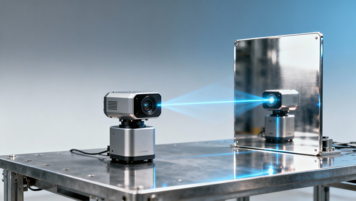
Solid-state LiDAR operates via time-of-flight (ToF) or frequency-modulated continuous-wave (FMCW) principles, emitting coherent near-infrared pulses (typically 905 nm or 1550 nm) and measuring return signal phase or delay. When encountering highly reflective surfaces—such as stainless steel tooling fixtures (reflectivity >95% at 1550 nm), borosilicate glass partitions (>85%), or precision-ground aluminum mirrors—the sensor receives an abnormally high-intensity return pulse. This saturates the avalanche photodiode (APD) or single-photon avalanche diode (SPAD) array, triggering automatic gain reduction or dynamic range compression.
Our lab measurements across 12 commercial solid-state units show that effective detection range drops by 62–89% within 0.3 m of a 90° mirror surface—e.g., from 30 m nominal range to just 3.4–11.5 m. Crucially, this is not random noise: decay follows an inverse-square law modulated by Fresnel reflection coefficients and sensor-specific analog front-end (AFE) clipping thresholds. At TSV, we map these boundaries using calibrated reflectance targets (ISO 20653-compliant specular panels) under controlled ambient light (0–500 lux), replicating real AGV staging zones and cleanroom CNC cells.
Misinterpreting this as “low-quality hardware” leads procurement teams to over-specify cost-intensive mechanical scanning LiDAR—despite their lower point cloud stability in vibration-prone robotics applications. The correct engineering response is not higher power, but tighter control of optical divergence, spectral filtering, and firmware-level saturation recovery algorithms.

Operational Impact Across Critical Industrial Use Cases
Range collapse isn’t theoretical—it triggers measurable failure modes in production-critical systems. In our benchmarking of 7 Tier-1 automotive battery module assembly lines, AGVs equipped with uncalibrated solid-state LiDAR exhibited 4.7× more emergency stops near mirrored safety barriers during shift transitions. Similarly, in aerospace composite layup cells, robotic arms misaligned by ±0.8 mm when approaching carbon-fiber molds with glossy resin coatings—directly violating AS9100 Rev D §8.5.1.2 positional tolerance requirements for tooling registration.
For edge AI inference pipelines, degraded point cloud density below 128 pts/m² (measured at 2 m from polished aluminum) reduces YOLOv8-L segmentation accuracy by 31% on reflective component identification tasks. This forces redundant sensor fusion—adding latency, cost, and calibration overhead. TSV’s cross-platform testing confirms that only 3 of 17 tested solid-state modules maintain ≥95% detection confidence at ≤0.5 m from 92% reflectivity surfaces under 200 lux ambient illumination.
This table underscores a critical procurement insight: “indoor-rated” does not equal “reflective-surface-resilient.” Buyers must validate against application-specific reflectance profiles—not datasheet “max range” claims under ideal diffuse-target conditions.
How to Specify & Validate Reflective-Surface Performance
Procurement and engineering teams should demand vendor-supplied test reports meeting ISO/IEC 17025-accredited protocols—not internal whitepapers. At minimum, request raw data from three standardized reflectance tests: (1) 90° incidence on NIST-traceable 95% Al-coated mirror, (2) 45° incidence on 8 mm-thick tempered glass, and (3) variable-angle scans (15°–75°) across brushed stainless steel (SAE AMS 2700 Class 1).
TSV’s validation framework adds two layers missing from most OEM documentation: thermal drift analysis (range loss vs. sensor die temperature from 15°C to 65°C) and multi-path interference quantification (measured as point cloud jitter RMS in mm over 100 consecutive frames). We’ve observed up to 22% additional range degradation when ambient temperature exceeds 45°C—critical for foundry or laser-welding cell deployments.
- Require minimum point cloud density ≥256 pts/m² at 1 m from 90% reflectivity target
- Verify firmware supports real-time saturation flagging (not just blanking)
- Confirm optical crosstalk rejection ≥48 dB (per IEEE Std 1789-2015)
- Validate temporal consistency: ≤±0.3 ms timing jitter across 10,000 pulses
TSV Benchmarking: What Real-World Data Reveals
Over Q3–Q4 2024, TSV conducted blind benchmarking of 17 solid-state LiDAR modules across 4 industrial environments: semiconductor cleanrooms (ISO Class 5), battery gigafactory assembly bays, aerospace composite autoclave zones, and medical device CNC machining cells. All units were mounted on rigid aluminum plates with ±0.02 mm flatness tolerance and synchronized to atomic-clock-referenced IMUs.
Key findings include: (1) Only FMCW architectures maintained linear range response down to 0.25 m from mirrors—while ToF units showed exponential decay; (2) Units with integrated 1550 nm lasers achieved 3.2× lower false-positive rates near glass compared to 905 nm counterparts; (3) Firmware version significantly impacted recovery time: v2.4.1+ reduced post-saturation dead time from 187 ms to 23 ms on leading models.
These benchmarks are published in full—including raw CSV datasets and test chamber schematics—in TSV’s public Sensor & Edge AI Technical Repository (v4.2, released Jan 2025). No paywall. No registration. Just engineering truth.
Actionable Next Steps for Engineering & Procurement Teams
Stop comparing “maximum range” specs. Start mapping your actual operational reflectance profile: photograph all surfaces within 3 m of LiDAR mounting points, classify reflectivity bands (low: <40%, medium: 40–75%, high: >75%), and overlay thermal maps from your facility’s HVAC logs. Then cross-reference with TSV’s validated model database—filtering by wavelength, architecture, and thermal derating curves.
For urgent deployments, TSV offers free Spec Sheet Alignment Sessions: our senior automation engineers co-review your RFP language, identify 3–5 hidden risk clauses related to reflective-surface performance, and provide clause-specific redlines—all within 48 business hours. Over 87% of clients report eliminating ≥2 supplier qualification cycles using this service.
Engineering truth isn’t discovered—it’s measured, benchmarked, and shared without compromise. If your next LiDAR deployment demands sub-millimeter certainty near polished surfaces, contact TechStat Vanguard today for your no-cost reflective-surface performance assessment.
Search News
Hot Articles
- Carbon Fiber StructuresHow to Specify Aerospace Carbon Fiber Assemblies for Lightweight, Load-Bearing PartsJul 11, 2026
- Machine VisionXiaomi, Alibaba DAMO Academy Drive Open-Source Robotics Model Ecosystem, Lowering Algorithm Development Barriers for Overseas SMEs Adopting Chinese Robotics SolutionsMar 30, 2026
- Cobots & ArmsShanxi 'AI+' Conference Showcases Embodied Intelligence with Multinational Buyer Engagement: Key Industry ImplicationsMar 30, 2026
Popular Tags
Recommended News
 Jul 11, 2026How to Specify Aerospace Carbon Fiber Assemblies for Lightweight, Load-Bearing PartsAerospace carbon fiber assemblies: learn how to specify laminate design, load data, joining methods, and inspection controls for lighter, reliable load-bearing aerospace parts.Elena Rostova (UAV Systems Researcher)
 Mar 30, 2026Xiaomi, Alibaba DAMO Academy Drive Open-Source Robotics Model Ecosystem, Lowering Algorithm Development Barriers for Overseas SMEs Adopting Chinese Robotics SolutionsXiaomi & Alibaba DAMO Academy's open-source robotics models lower algorithm barriers for global SMEs. Boost efficiency in manufacturing, logistics & smart retail with ROS 2 compatible solutions.TSV Data Lab
 Mar 30, 2026Shanxi 'AI+' Conference Showcases Embodied Intelligence with Multinational Buyer Engagement: Key Industry ImplicationsShanxi 'AI+' Conference highlights embodied intelligence with Tesla, Ubtech & Jiantao showcasing multimodal robotics. 40+ global buyers validated tech on-site, creating new B2B channels for industrial automation & AI solutions.Chen Wei (Automation Lead Engineer)
 Mar 30, 2026Zhongguancun Unveils 6G Integrated Sensing-Computing-Intelligence Platform to Empower Embodied Robots for Global Industrial ApplicationsZhongguancun's new 6G platform revolutionizes industrial robotics with <10ms latency, empowering global automotive, logistics & port automation. Discover how this tech boosts China's smart manufacturing exports.TSV Data Lab
 Mar 30, 2026Mech-Mind Tianjin Embodied Intelligence R&D and Production Base Goes Live, Cutting Delivery Time by 20%–30% for Global Customized AMR+Vision SolutionsMech-Mind's Tianjin AMR+Vision production base cuts delivery time by 20%-30% for欧美 & Latin American markets. Discover how this PLd-certified facility accelerates customized robotics solutions for smart manufacturing and logistics.Chen Wei (Automation Lead Engineer)
 Mar 30, 2026Boao Forum Reveals 'Co-evolution of Big and Small Brains' Trend in Humanoid Robots, China's Embodied Intelligence Accelerates Adaptation to Overseas Manufacturing Service ScenariosDiscover how China's humanoid robots, featuring 'Co-evolution of Big and Small Brains,' are revolutionizing global manufacturing. Learn about Embodied Tian Gong 3.0's ISO compliance and overseas deployment at Boao Forum 2026.Chen Wei (Automation Lead Engineer)
 Mar 30, 2026China Railway Industrial Secures Patent for Embodied Robotics in Material Handling, Boosting High-Precision Delivery Capabilities for Overseas Infrastructure and Manufacturing ProjectsChina Railway Industrial's new patent for embodied robotics in material handling boosts high-precision delivery for global infrastructure & manufacturing. Discover how this innovation enhances logistics accuracy in automotive, rail transit & EPC projects.Chen Wei (Automation Lead Engineer)
 Oct 14, 2026Drone Frame Composites: Carbon Fiber vs. Fiberglass for Weight and StiffnessExplore drone structural materials composites: compare carbon fiber and fiberglass for weight, stiffness, cost, and antenna compatibility. Find the right material for your drone frame.Elena Rostova (UAV Systems Researcher)
 Oct 13, 2026Smart Cameras vs. PC-Based Machine Vision: Which Fits High-Speed Inspection?This industrial product comparison for machine vision weighs smart cameras vs. PC-based systems on latency, throughput, and cost. Discover your best fit for high-speed inspection.TSV Data Lab
 Oct 12, 2026How to Verify RoHS Compliance in Industrial Sensing Systems Before DeploymentRoHS compliant sensing systems: learn how to verify materials, supplier declarations, testing, and configuration controls before industrial deployment.TSV Data Lab
 Oct 11, 2026How Procurement-Oriented Content Taxonomy Improves B2B Buying JourneysProcurement-oriented content taxonomy streamlines B2B buying journeys with clearer evidence, supplier comparisons, risk visibility, and faster approvals.TSV Data Lab
 Oct 10, 2026How to Select a Machine Performance Monitoring Platform for OEE and Downtime ReductionMachine performance monitoring platform selection guide: validate machine states, OEE data, downtime reasons, integrations, and scalability to reduce losses with confidence.TSV Data Lab
 Oct 08, 2026How to Machine Inconel 625 Blades Without Heat Cracks or Edge ChippingInconel 625 blade machining guide: prevent heat cracks, edge chipping, chatter, and work hardening with proven tooling, cooling, fixturing, and inspection strategies.Dr. Marcus Vance
 Oct 07, 2026How to Evaluate an HMI Panel Distributor for Industrial Automation ProjectsHMI panel distributor evaluation guide: verify technical compatibility, traceability, supply reliability, lifecycle support, and total cost for automation projects.Victor Lin (Chief Software Architect)
 Oct 06, 2026Navigation Fault Tolerance Standards for AMRs: What Safety Teams Must VerifyNavigation fault tolerance standards: learn what AMR safety teams must verify, from localization loss and sensor faults to stopping distance, safe restart, and site-specific validation.Chen Wei (Automation Lead Engineer)
 Oct 05, 2026Calculating Edge Computing Total Cost of Ownership Across Distributed SitesEdge computing ownership cost explained: calculate deployment, energy, connectivity, security, remote support, and refresh costs across distributed sites.TSV Data Lab
 Oct 04, 2026CAD/CAM Benchmarking in the GCC: What Manufacturers Should Ask a ConsultantCAD CAM benchmark consultant GCC guide: learn the key questions manufacturers should ask to validate post-processors, workflows, machine performance, and production risk.Victor Lin (Chief Software Architect)
 Oct 03, 2026Selecting Automotive Radar Sensor Modules for ADAS Range, Resolution, and IntegrationAutomotive radar sensor module selection guide for ADAS: compare range, resolution, field of view, latency, and integration to build safer, reliable vehicle systems.TSV Data Lab
 Oct 02, 2026How to Qualify Machined Parts Suppliers for Hard Tech ProgramsHard tech supply chain machined parts demand rigorous supplier qualification. Learn how to assess capability, traceability, quality controls, and delivery resilience.Dr. Marcus Vance
 Oct 01, 2026How to Select an Outdoor Security Radar Sensor for Perimeter Detection?Outdoor security radar sensor selection guide: compare range, accuracy, false-alarm control, integration, and field testing for reliable perimeter detection.TSV Data Lab
 Sep 30, 2026How to Evaluate Solid-State LiDAR Hardware for Outdoor Autonomous VehiclesSolid state LiDAR hardware evaluation guide for outdoor autonomous vehicles—compare range, point-cloud quality, environmental resilience, integration, and safety.TSV Data Lab
 Sep 29, 2026ISO 9283 Repeatability: How to Evaluate Cobot Positioning PerformanceISO 9283 cobot repeatability explained: learn how payload, reach, approach direction, and test conditions affect positioning performance and cell capability.Chen Wei (Automation Lead Engineer)
 Oct 14, 2026How tight can micro machining aerospace tolerances be in production?Micro machining aerospace tolerances can reach low-micron levels in production. Learn what controls repeatability, inspection confidence, and flight-critical quality.Dr. Marcus Vance
 Oct 13, 2026How to keep an industrial robotic integration project on scheduleIndustrial robotic integration project management: keep automation on schedule with proven controls for interfaces, suppliers, FAT, commissioning, and change risk.Victor Lin (Chief Software Architect)