
Is Solid-State LiDAR Accurate Enough for Tight Robotics Navigation?
Publication Date
author
For robotics teams navigating narrow aisles, blind corners, and mixed-traffic floors, the real question is whether solid-state LiDAR for robotics navigation delivers enough solid-state LiDAR range accuracy and solid-state LiDAR point cloud density to make safe, repeatable decisions. This article examines how these metrics affect tight-path performance, obstacle detection, and system-level reliability for engineers, operators, buyers, and technology leaders.
In warehouse automation, AMRs, AGVs, inspection robots, and service platforms rarely fail because of one headline specification alone. They fail when several borderline parameters stack up: distance error at 3-8 m, sparse point returns at oblique angles, latency above the control loop budget, or poor performance on dark and reflective surfaces. For teams working under narrow clearance conditions such as 150-300 mm side margins, those details directly affect navigation confidence.
TechStat Vanguard approaches this issue from an engineering and procurement perspective rather than a marketing perspective. The practical question is not whether solid-state LiDAR is “good” in general, but whether a given sensor architecture is accurate enough for a defined path width, robot speed, stopping distance, and safety layer design. That distinction matters when drafting specifications, comparing suppliers, or validating deployment readiness.
What “accurate enough” means in tight robotics navigation
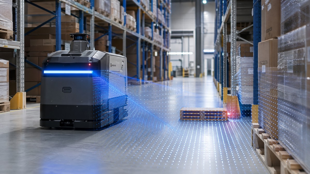
Accuracy in tight navigation is a system-level requirement, not a single sensor number. A robot moving through 900 mm aisles with a 600 mm chassis and payload swing cannot rely on broad claims such as “centimeter-level precision” unless that claim is mapped to actual operating distance, scan refresh, localization method, and obstacle class. For most indoor robots, the useful evaluation window is often 0.2-10 m rather than the maximum advertised range.
In practical engineering terms, three numbers usually matter first: range accuracy, angular resolution, and point cloud density. If a sensor has a distance error of ±30 mm at 5 m, that may be acceptable in a 2.5 m corridor but risky in a mixed-traffic aisle where the robot must clear pallet edges, forks, or human legs with only 100-150 mm of decision margin. A navigation stack can compensate for some uncertainty, but compensation has limits.
Operators and buyers should also separate mapping accuracy from real-time obstacle accuracy. A robot may build an acceptable static map during commissioning, yet still struggle in live traffic because moving objects, reflective wrappers, floor transitions, or steel posts reduce return consistency. In these cases, a sensor that performs well in a demo lane may underperform during 16-20 hour daily operation.
Key thresholds engineers usually test first
When TSV reviews robotics sensing requirements, the first pass often focuses on a few threshold questions rather than a long feature list:
- Can the sensor maintain stable obstacle contour detection within 0.5-6 m, where most indoor avoidance decisions happen?
- Does the update rate support the robot control loop, typically 10-25 Hz for low-speed AMRs and higher for agile platforms?
- Can the point cloud distinguish narrow protrusions, pallet gaps, and low objects between 50-150 mm in size?
- How much accuracy drift appears on black plastic, shrink wrap, glass, or polished metal?
The table below frames how “accurate enough” changes by application. It is not a universal acceptance standard, but it is a useful benchmarking reference for specification drafting.
The key conclusion is that solid-state LiDAR can be accurate enough, but only if the acceptance criteria are tied to clearance, speed, and object type. A broad maximum-range claim, such as 100 m or 200 m, says very little about whether the sensor is suitable for tight indoor robotics navigation.
Why range accuracy and point cloud density matter more than headline range
Many robotics buying teams are initially drawn to maximum detection range because it is easy to compare. In tight robotics navigation, however, the decisive operating band is often short to mid-range. A sensor used for indoor AMR navigation may spend more than 90% of its decision time interpreting objects inside 8 m, and much of that inside 3 m. That makes short-range accuracy and dense spatial sampling far more important than long-range capability alone.
Point cloud density directly affects shape reconstruction. If the point spacing is too wide, the navigation stack may interpret a pallet opening, cart wheel, or table leg incorrectly. In a corridor with complex geometry, sparse returns can cause contour aliasing, where the robot sees an obstacle edge later than expected or smooths a real obstruction into the background. The result is conservative motion, unnecessary stops, or edge strikes.
Angular resolution also interacts with density. Two sensors may publish similar field-of-view values, yet one may produce a far more usable obstacle model because its effective angular spacing is tighter in the forward driving region. For buyers, this is why raw field of view values such as 90°, 120°, or 270° should never be reviewed without scan pattern and usable point distribution.
How to read sensor claims more critically
The most useful comparison is not “Which solid-state LiDAR has the longest range?” but “Which sensor maintains repeatable distance and contour fidelity under our materials, lighting, and motion profile?” The following table highlights specification lines that deserve closer scrutiny during evaluation.
For technology leaders, this means benchmark planning should emphasize object classes, angle of incidence, and target distances. A sensor with lower stated range but better short-range stability may outperform a longer-range competitor in real navigation reliability. That is a more valuable result for procurement than an impressive brochure number.
A practical rule for narrow-path robotics
If the robot must navigate with less than 200 mm average side clearance, evaluate not just whether the object is detected, but whether its boundary is stable enough over 10-20 consecutive frames to support repeatable path planning. In many deployments, consistency across time matters more than single-frame sharpness.
System-level factors that decide whether solid-state LiDAR succeeds
Even a strong sensor can underdeliver if the robot architecture around it is weak. Tight robotics navigation depends on a chain that includes mounting position, vibration isolation, timestamp quality, fusion logic, planner tuning, braking performance, and safety zoning. A LiDAR that is accurate on a lab bench may produce poor field results if mounted too low, too high, or behind a protective window that introduces contamination or glare.
Latency budgeting is especially important. Suppose a robot moves at 1.2 m/s and the sensing-to-actuation delay reaches 180 ms. The vehicle can travel more than 200 mm before the command takes effect, not including mechanical braking distance. In a tight aisle, that distance can consume the entire safety margin. This is why sensor performance should always be reviewed against full-stack response time, not in isolation.
Environmental robustness also decides field accuracy. Dust, forklift vibration, thermal variation between 5°C and 40°C, and surface contamination can all alter point return quality. In facilities with reflective packaging or metal cages, false positives and partial misses become more common. That is not a reason to reject solid-state LiDAR, but it is a reason to validate it under actual floor conditions for at least 2-4 operating weeks.
Implementation checks before full procurement
Before approving a large-volume purchase, engineering and sourcing teams should run a structured pilot. The following checklist helps reduce trial-and-error costs:
- Test three object groups: human legs and shoes, pallet and rack edges, and low-profile floor obstacles between 30-100 mm high.
- Measure behavior at three speed bands, such as 0.4 m/s, 0.8 m/s, and 1.2 m/s, to observe planner stability.
- Validate at least two lighting and material conditions, including dark surfaces and reflective wrapping.
- Record frame-to-frame contour stability and not just binary detection success.
- Confirm cleaning frequency, protective window durability, and maintenance access over a 30-day cycle.
For operators, the practical outcome is smoother navigation and fewer nuisance stops. For procurement teams, the outcome is a cleaner technical comparison between suppliers. For executives, it reduces the risk of paying for a specification that looks advanced but does not improve throughput or safety in the target layout.
How buyers and engineering teams should compare solid-state LiDAR options
A useful sourcing process begins with the application envelope rather than a supplier shortlist. In other words, define aisle width, robot dimensions, minimum obstacle size, target speed, stop distance, and traffic complexity first. Once those constraints are clear, sensor comparison becomes more objective. This approach aligns with TSV’s core principle that parameters should drive decisions, not broad performance labels.
Procurement teams should also distinguish between bill-of-material cost and total deployment cost. A lower-cost unit may require extra sensors, repeated tuning, or more conservative robot speeds, which can reduce fleet productivity. In some cases, paying 15-25% more for a sensor with better near-field stability may lower the overall cost of commissioning and support.
Decision-makers should request evidence in a form that can be audited. Useful evidence includes detection performance by object type, error behavior across distance bands, environmental test notes, interface latency ranges, and maintenance guidance. If a vendor cannot show how performance changes between 1 m and 8 m, or between matte and reflective targets, the risk of underdefined procurement rises.
A procurement-oriented comparison framework
The matrix below can help buyers, robotics engineers, and technical managers structure an RFQ or supplier review process.
This framework shifts the conversation from feature marketing to operational value. It also helps align the needs of different stakeholders: researchers want measurable performance, operators want predictable behavior, procurement wants comparable evidence, and executives want deployment risk under control.
Common buying mistakes to avoid
- Choosing on maximum range alone when the robot works mostly inside 8 m.
- Ignoring the effect of mounting height and field-of-view occlusions.
- Evaluating only in static demos instead of mixed-traffic runs.
- Assuming all solid-state LiDAR architectures produce similar point quality.
- Skipping lifecycle considerations such as cleaning frequency and diagnostics access.
FAQ and deployment guidance for real-world teams
Many search and buying conversations around solid-state LiDAR for robotics navigation come down to a small group of recurring questions. The answers are rarely universal, but there are practical guidelines that help teams shorten qualification cycles and reduce failed pilots.
Is solid-state LiDAR enough on its own for tight indoor navigation?
Sometimes yes, but not always. In lower-speed indoor robots operating around 0.4-0.8 m/s, a well-selected solid-state LiDAR may be sufficient for primary perception if the environment is structured and the safety concept is strong. In more dynamic settings, teams often combine LiDAR with wheel odometry, IMU, cameras, or safety scanners to improve robustness at corners, crossings, and cluttered zones.
What point cloud quality is usually needed for narrow aisles?
There is no single threshold, but the sensor should reconstruct thin and irregular geometry reliably within the real working band, especially 1-5 m. If the robot must interpret pallet edges, forks, and low obstacles with less than 200 mm side margin, denser and more stable returns are generally more valuable than additional long-range reach.
How long should a practical evaluation last before volume purchase?
A short bench check may take 2-5 days, but a realistic floor validation should usually last 2-4 weeks. That allows teams to observe contamination effects, shift-to-shift variation, route repetition, and performance around real traffic. For multi-site deployment, one pilot environment is rarely enough if floor materials and lighting differ significantly.
What should decision-makers ask suppliers before approval?
Ask for performance data by distance band, examples of challenging surface behavior, interface latency details, and maintenance requirements. Also ask how the sensor behaves on partial targets and at oblique angles. These questions are more revealing than generic claims about intelligence, innovation, or next-generation capability.
Solid-state LiDAR is often accurate enough for tight robotics navigation, but only when teams define accuracy as an operational envelope rather than a marketing phrase. Near-field precision, usable point cloud density, latency, environmental tolerance, and integration quality together determine whether a robot can navigate narrow aisles and blind corners safely and repeatably.
For engineering teams, the right next step is to convert layout constraints into measurable sensor requirements. For buyers and executives, the priority is to compare suppliers on evidence that reflects real floor conditions, lifecycle effort, and deployment risk. If you are evaluating sensors, AMR perception stacks, or hard-tech sourcing options, contact TechStat Vanguard to discuss a more rigorous benchmarking framework, request a tailored evaluation checklist, or explore deeper robotics sensing analysis.
Search News
Hot Articles
- Carbon Fiber StructuresHow to Specify Aerospace Carbon Fiber Assemblies for Lightweight, Load-Bearing PartsJul 11, 2026
- Machine VisionXiaomi, Alibaba DAMO Academy Drive Open-Source Robotics Model Ecosystem, Lowering Algorithm Development Barriers for Overseas SMEs Adopting Chinese Robotics SolutionsMar 30, 2026
- Cobots & ArmsShanxi 'AI+' Conference Showcases Embodied Intelligence with Multinational Buyer Engagement: Key Industry ImplicationsMar 30, 2026
Popular Tags
Recommended News
 Jul 11, 2026How to Specify Aerospace Carbon Fiber Assemblies for Lightweight, Load-Bearing PartsAerospace carbon fiber assemblies: learn how to specify laminate design, load data, joining methods, and inspection controls for lighter, reliable load-bearing aerospace parts.Elena Rostova (UAV Systems Researcher)
 Mar 30, 2026Xiaomi, Alibaba DAMO Academy Drive Open-Source Robotics Model Ecosystem, Lowering Algorithm Development Barriers for Overseas SMEs Adopting Chinese Robotics SolutionsXiaomi & Alibaba DAMO Academy's open-source robotics models lower algorithm barriers for global SMEs. Boost efficiency in manufacturing, logistics & smart retail with ROS 2 compatible solutions.TSV Data Lab
 Mar 30, 2026Shanxi 'AI+' Conference Showcases Embodied Intelligence with Multinational Buyer Engagement: Key Industry ImplicationsShanxi 'AI+' Conference highlights embodied intelligence with Tesla, Ubtech & Jiantao showcasing multimodal robotics. 40+ global buyers validated tech on-site, creating new B2B channels for industrial automation & AI solutions.Chen Wei (Automation Lead Engineer)
 Mar 30, 2026Zhongguancun Unveils 6G Integrated Sensing-Computing-Intelligence Platform to Empower Embodied Robots for Global Industrial ApplicationsZhongguancun's new 6G platform revolutionizes industrial robotics with <10ms latency, empowering global automotive, logistics & port automation. Discover how this tech boosts China's smart manufacturing exports.TSV Data Lab
 Mar 30, 2026Mech-Mind Tianjin Embodied Intelligence R&D and Production Base Goes Live, Cutting Delivery Time by 20%–30% for Global Customized AMR+Vision SolutionsMech-Mind's Tianjin AMR+Vision production base cuts delivery time by 20%-30% for欧美 & Latin American markets. Discover how this PLd-certified facility accelerates customized robotics solutions for smart manufacturing and logistics.Chen Wei (Automation Lead Engineer)
 Mar 30, 2026Boao Forum Reveals 'Co-evolution of Big and Small Brains' Trend in Humanoid Robots, China's Embodied Intelligence Accelerates Adaptation to Overseas Manufacturing Service ScenariosDiscover how China's humanoid robots, featuring 'Co-evolution of Big and Small Brains,' are revolutionizing global manufacturing. Learn about Embodied Tian Gong 3.0's ISO compliance and overseas deployment at Boao Forum 2026.Chen Wei (Automation Lead Engineer)
 Mar 30, 2026China Railway Industrial Secures Patent for Embodied Robotics in Material Handling, Boosting High-Precision Delivery Capabilities for Overseas Infrastructure and Manufacturing ProjectsChina Railway Industrial's new patent for embodied robotics in material handling boosts high-precision delivery for global infrastructure & manufacturing. Discover how this innovation enhances logistics accuracy in automotive, rail transit & EPC projects.Chen Wei (Automation Lead Engineer)
 Oct 25, 2026Hesai Leads Global ADAS Main Lidar Shipments in Yole’s 2026 ReportHesai led global ADAS main lidar shipments with a 43% share in 2025, according to Yole’s 2026 report. Explore what this ranking reveals about its automotive market position.TSV Data Lab
 Oct 25, 2026Choosing an Aerospace Materials Manufacturer: Quality and Traceability ChecksChoosing an aerospace materials manufacturer? Learn how to verify certifications, test reports, and lot traceability to qualify suppliers confidently and reduce costly sourcing risks.Dr. Marcus Vance
 Oct 24, 2026Guotai Haitong: Global Entry-Level 3D Printer Shipments Rose 39% in Q1 2026Entry-level 3D printer shipments rose 39% in Q1 2026, Guotai Haitong reports. Explore how AI, multicolor printing and print farms are shaping market growth.Dr. Marcus Vance
 Oct 24, 2026Choosing an Industrial Vision Inspection Supplier: Acceptance Tests That MatterChoose an industrial vision inspection supplier with confidence. Discover acceptance tests for defect detection, false rejects, production speed, and reliable part rejection before you buy.TSV Data Lab
 Oct 23, 2026US Navy Raises Gecko Robotics Contract Ceiling to $300M for Robotic Fleet MaintenanceUS Navy raises Gecko Robotics’ contract ceiling to $300M for Pacific Fleet robotic inspections. Explore potential opportunities for maintenance suppliers and key procurement considerations.Chen Wei (Automation Lead Engineer)
 Oct 23, 2026Choosing Industrial Sensing Systems for Global Plants: Protocol CompatibilityCompare industrial sensing systems international buyers can trust. Explore protocol compatibility, reduce integration risks, and select proven configurations for reliable global plant deployments.TSV Data Lab
 Oct 22, 2026KUKA Showcases Physical AI and iiQKA.AI Vision at NVIDIA GTC BerlinExplore KUKA’s Physical AI showcase at NVIDIA GTC Berlin and discover how iiQKA.AI Vision aims to simplify robotic vision integration and improve 2D and 3D scene recognition.TSV Data Lab
 Oct 22, 2026Robotic Machining of Advanced Composites: What Tolerances Are Achievable?Explore advanced materials machining robotics: discover what drives achievable composite tolerances and how to validate accuracy before investing in your next machining system.Dr. Marcus Vance
 Oct 21, 2026China’s Industrial Robot Exports Near RMB 10 Billion in First Nine Months of 2026China’s industrial robot exports neared RMB 10 billion in January–September 2026, with value rising faster than volume. Explore the data and what it could mean for suppliers.Chen Wei (Automation Lead Engineer)
 Oct 21, 2026Low-Latency Industrial Data Processing: Pricing and Key Cost DriversExplore industrial data latency price drivers, from edge hardware to integration and support. Learn how to compare quotes, verify performance, and avoid unnecessary costs.TSV Data Lab
 Oct 20, 2026KUKA Launches iiQKA.AI Vision to Simplify Industrial Image ProcessingKUKA iiQKA.AI Vision simplifies industrial image processing with controller-based 2D and 3D vision. Explore drag-and-drop setup for vision-guided automation.TSV Data Lab
 Oct 20, 2026Smart Industrial Edge Devices: Key Criteria for Legacy PLC IntegrationChoose smart industrial edge devices for legacy PLC integration. Discover key criteria for compatibility, data quality, security, and reliable collection without disrupting control.TSV Data Lab
 Oct 19, 2026Choosing a Radar Sensor by Application: Range, Resolution, and Field of ViewSimplify radar sensor application based product selection. Compare range, resolution, and field of view to avoid blind spots and choose with confidence. Explore the guide.TSV Data Lab
 Oct 18, 2026Comparing Material Options for Procurement: Specs, Costs, and Supply RisksExplore procurement oriented technical content on material options, specs, costs, and supply risks. Compare alternatives to cut hidden expenses and make confident sourcing decisions.Dr. Marcus Vance
 Oct 17, 20265-Axis CNC Positioning Accuracy: How to Interpret ISO 230-2 Test ResultsAssess 5 axis CNC machining positioning accuracy with ISO 230-2. Learn to interpret repeatability, reversal error, and test conditions to compare suppliers and make confident acceptance decisions.Dr. Marcus Vance
 Oct 16, 2026Choosing a Rugged Edge AI Box Supplier: Thermal Tests and Lifecycle SupportChoose a rugged edge AI box supplier with proven thermal performance and reliable lifecycle support. Discover the tests and commitments to verify before you buy.TSV Data Lab
 Oct 15, 2026R&D Cost Reduction Services: How to Evaluate Fees, Savings, and ROIEvaluate R&D cost reduction services with confidence. Compare fees, verify savings, and calculate ROI without compromising performance. Discover how to choose a provider that delivers real value.Chen Wei (Automation Lead Engineer)























