Does industrial PC MTBF reflect real factory uptime?
Publication Date
author
Industrial PC MTBF figures often look reassuring on spec sheets, but do they truly represent uptime on a vibrating, dusty, heat-loaded factory floor? For engineers, buyers, and plant leaders comparing fanless pc thermal dissipation test results, industrial pc mtbf calculation methods, and real-world maintenance risk, the answer is rarely simple. This article examines how MTBF should be interpreted, what it leaves out, and how to evaluate industrial computers with data that better reflects actual production reliability.
For B2B teams responsible for automation lines, edge computing nodes, machine vision stations, and control cabinets, the gap between a published MTBF value and actual factory uptime can be expensive. A system rated at 50,000 to 100,000 hours may still suffer avoidable shutdowns if heat, power instability, connector fatigue, or poor maintenance planning are ignored.
At TechStat Vanguard, the practical question is not whether MTBF matters. It does. The real question is how much weight it should carry compared with thermal design, ingress protection, storage endurance, vibration resistance, serviceability, and workload matching. In procurement terms, MTBF is one data point, not a full reliability verdict.
What MTBF really measures in industrial computing
MTBF, or Mean Time Between Failures, is a statistical estimate of the average operating time between inherent failures for repairable equipment. In industrial PC selection, it is commonly expressed in hours, such as 40,000 hours, 70,000 hours, or 100,000 hours. That sounds straightforward, but the number is usually derived from component-level reliability models under defined assumptions rather than long-term field operation in a specific plant.
In many cases, industrial pc mtbf calculation is based on standards or prediction models that estimate failure rates from component databases, temperature assumptions, and operating profiles. These calculations can be useful for comparison, especially when two systems are built around different CPUs, power modules, SSD grades, or cooling architectures. However, they are not a direct guarantee that a unit will run uninterrupted for 8.2 years just because the MTBF is listed near 72,000 hours.
Another common misunderstanding is to treat MTBF as a probability of zero failure. It is not. A higher MTBF generally indicates lower predicted failure frequency across a population of devices, but any single device can fail earlier. In a factory with 50, 100, or 300 deployed industrial PCs, even a statistically strong design may still generate several service events over a 12 to 36 month operating cycle.
Why spec-sheet MTBF can look more certain than it is
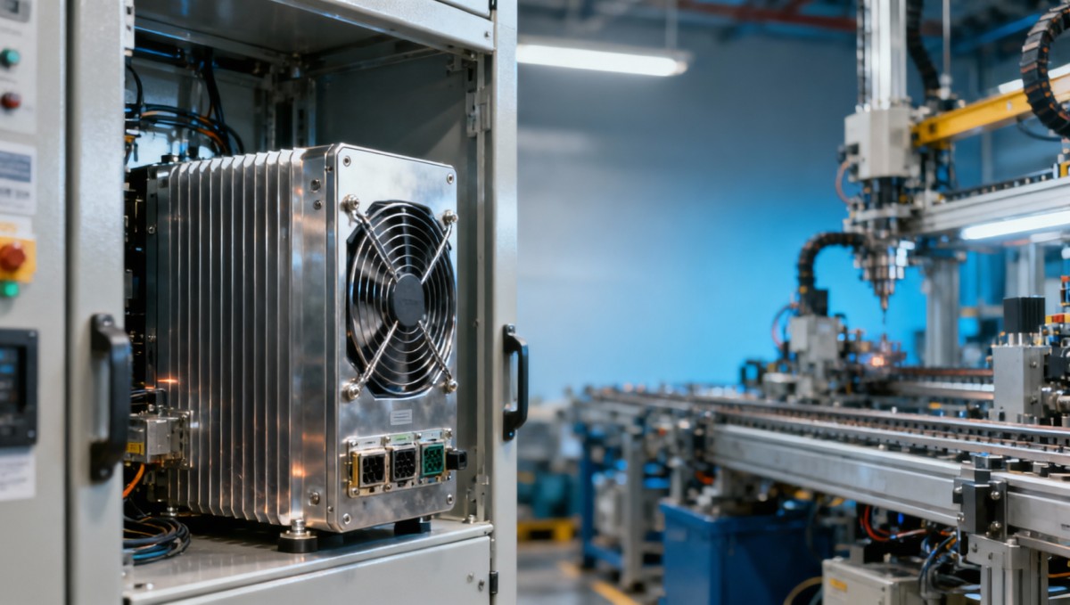
Published values often assume controlled ambient temperatures, stable power quality, moderate duty cycles, and a fixed component temperature rise. Real facilities are messier. A fanless computer installed in a sealed cabinet at 45°C ambient may operate 10°C to 20°C hotter internally than the condition used in a reliability estimate. Since electronic component life is highly temperature sensitive, that difference can materially affect actual uptime.
MTBF also says little about maintenance speed. Two PCs may have similar predicted reliability, but if one uses modular I/O, accessible storage, and a standard 9 to 36 VDC input, it can be restored faster after a fault than a compact unit with proprietary parts. Plant uptime depends on both failure frequency and recovery time.
A practical interpretation framework
- Use MTBF as a comparative indicator, not a standalone purchasing decision.
- Ask whether the figure was derived at 25°C, 40°C, or another reference condition.
- Check whether storage, power supply, and connectors were included in the model.
- Review whether the workload is light HMI processing or continuous edge AI inference.
- Compare MTBF alongside service response time, spare parts strategy, and thermal test evidence.
For operators and decision-makers, this approach reduces the risk of buying a system that looks strong on paper but underperforms in a hot, dusty, high-vibration production zone.
Why real factory uptime depends on more than MTBF
Actual uptime is shaped by the interaction between device design and plant conditions. An industrial PC mounted on an AGV controller rack, near a stamping line, or inside a welding cell sees stresses very different from an office-side data terminal. Dust loading, oil mist, EMI, repetitive shock, and 24/7 duty cycles often determine field performance more than a headline MTBF number.
Thermal management is one of the most decisive factors. Fanless pc thermal dissipation test data should show how the enclosure behaves at multiple ambient points, such as 25°C, 40°C, 50°C, and sometimes 60°C. A system that throttles CPU frequency after 30 minutes under sustained load may not fail immediately, but it can trigger latency spikes, machine vision frame drops, or unstable PLC communication that effectively reduces production uptime.
Power quality is another hidden uptime variable. Brownouts, voltage dips, and switching noise can corrupt storage writes or force reboots. In facilities where DC power rails fluctuate, a wider input range such as 9 to 36 VDC or 12 to 24 VDC, combined with surge and reverse-polarity protection, can be more important than a small MTBF advantage on paper.
Field conditions that often shorten real service life
The table below highlights why a published industrial PC MTBF value should always be read together with environmental and design data.
Search News
Hot Articles
- Carbon Fiber StructuresHow to Specify Aerospace Carbon Fiber Assemblies for Lightweight, Load-Bearing PartsJul 11, 2026
- Machine VisionXiaomi, Alibaba DAMO Academy Drive Open-Source Robotics Model Ecosystem, Lowering Algorithm Development Barriers for Overseas SMEs Adopting Chinese Robotics SolutionsMar 30, 2026
- Cobots & ArmsShanxi 'AI+' Conference Showcases Embodied Intelligence with Multinational Buyer Engagement: Key Industry ImplicationsMar 30, 2026
Popular Tags
Recommended News
 Jul 11, 2026How to Specify Aerospace Carbon Fiber Assemblies for Lightweight, Load-Bearing PartsAerospace carbon fiber assemblies: learn how to specify laminate design, load data, joining methods, and inspection controls for lighter, reliable load-bearing aerospace parts.Elena Rostova (UAV Systems Researcher)
 Mar 30, 2026Xiaomi, Alibaba DAMO Academy Drive Open-Source Robotics Model Ecosystem, Lowering Algorithm Development Barriers for Overseas SMEs Adopting Chinese Robotics SolutionsXiaomi & Alibaba DAMO Academy's open-source robotics models lower algorithm barriers for global SMEs. Boost efficiency in manufacturing, logistics & smart retail with ROS 2 compatible solutions.TSV Data Lab
 Mar 30, 2026Shanxi 'AI+' Conference Showcases Embodied Intelligence with Multinational Buyer Engagement: Key Industry ImplicationsShanxi 'AI+' Conference highlights embodied intelligence with Tesla, Ubtech & Jiantao showcasing multimodal robotics. 40+ global buyers validated tech on-site, creating new B2B channels for industrial automation & AI solutions.Chen Wei (Automation Lead Engineer)
 Mar 30, 2026Zhongguancun Unveils 6G Integrated Sensing-Computing-Intelligence Platform to Empower Embodied Robots for Global Industrial ApplicationsZhongguancun's new 6G platform revolutionizes industrial robotics with <10ms latency, empowering global automotive, logistics & port automation. Discover how this tech boosts China's smart manufacturing exports.TSV Data Lab
 Mar 30, 2026Mech-Mind Tianjin Embodied Intelligence R&D and Production Base Goes Live, Cutting Delivery Time by 20%–30% for Global Customized AMR+Vision SolutionsMech-Mind's Tianjin AMR+Vision production base cuts delivery time by 20%-30% for欧美 & Latin American markets. Discover how this PLd-certified facility accelerates customized robotics solutions for smart manufacturing and logistics.Chen Wei (Automation Lead Engineer)
 Mar 30, 2026Boao Forum Reveals 'Co-evolution of Big and Small Brains' Trend in Humanoid Robots, China's Embodied Intelligence Accelerates Adaptation to Overseas Manufacturing Service ScenariosDiscover how China's humanoid robots, featuring 'Co-evolution of Big and Small Brains,' are revolutionizing global manufacturing. Learn about Embodied Tian Gong 3.0's ISO compliance and overseas deployment at Boao Forum 2026.Chen Wei (Automation Lead Engineer)
 Mar 30, 2026China Railway Industrial Secures Patent for Embodied Robotics in Material Handling, Boosting High-Precision Delivery Capabilities for Overseas Infrastructure and Manufacturing ProjectsChina Railway Industrial's new patent for embodied robotics in material handling boosts high-precision delivery for global infrastructure & manufacturing. Discover how this innovation enhances logistics accuracy in automotive, rail transit & EPC projects.Chen Wei (Automation Lead Engineer)
 Oct 16, 2026Choosing a Rugged Edge AI Box Supplier: Thermal Tests and Lifecycle SupportChoose a rugged edge AI box supplier with proven thermal performance and reliable lifecycle support. Discover the tests and commitments to verify before you buy.TSV Data Lab
 Oct 15, 2026R&D Cost Reduction Services: How to Evaluate Fees, Savings, and ROIEvaluate R&D cost reduction services with confidence. Compare fees, verify savings, and calculate ROI without compromising performance. Discover how to choose a provider that delivers real value.Chen Wei (Automation Lead Engineer)
 Oct 15, 2026How Should You Compare TechStat Vanguard 5-Axis CNC Tolerances?TechStat Vanguard 5-axis CNC tolerance comparison: learn how to verify part accuracy, assess inspection evidence, and choose suppliers that reliably meet your drawing requirements.Dr. Marcus Vance
 Oct 14, 2026Drone Frame Composites: Carbon Fiber vs. Fiberglass for Weight and StiffnessExplore drone structural materials composites: compare carbon fiber and fiberglass for weight, stiffness, cost, and antenna compatibility. Find the right material for your drone frame.Elena Rostova (UAV Systems Researcher)
 Oct 13, 2026Smart Cameras vs. PC-Based Machine Vision: Which Fits High-Speed Inspection?This industrial product comparison for machine vision weighs smart cameras vs. PC-based systems on latency, throughput, and cost. Discover your best fit for high-speed inspection.TSV Data Lab
 Oct 12, 2026How to Verify RoHS Compliance in Industrial Sensing Systems Before DeploymentRoHS compliant sensing systems: learn how to verify materials, supplier declarations, testing, and configuration controls before industrial deployment.TSV Data Lab
 Oct 11, 2026How Procurement-Oriented Content Taxonomy Improves B2B Buying JourneysProcurement-oriented content taxonomy streamlines B2B buying journeys with clearer evidence, supplier comparisons, risk visibility, and faster approvals.TSV Data Lab
 Oct 10, 2026How to Select a Machine Performance Monitoring Platform for OEE and Downtime ReductionMachine performance monitoring platform selection guide: validate machine states, OEE data, downtime reasons, integrations, and scalability to reduce losses with confidence.TSV Data Lab
 Oct 08, 2026How to Machine Inconel 625 Blades Without Heat Cracks or Edge ChippingInconel 625 blade machining guide: prevent heat cracks, edge chipping, chatter, and work hardening with proven tooling, cooling, fixturing, and inspection strategies.Dr. Marcus Vance
 Oct 07, 2026How to Evaluate an HMI Panel Distributor for Industrial Automation ProjectsHMI panel distributor evaluation guide: verify technical compatibility, traceability, supply reliability, lifecycle support, and total cost for automation projects.Victor Lin (Chief Software Architect)
 Oct 06, 2026Navigation Fault Tolerance Standards for AMRs: What Safety Teams Must VerifyNavigation fault tolerance standards: learn what AMR safety teams must verify, from localization loss and sensor faults to stopping distance, safe restart, and site-specific validation.Chen Wei (Automation Lead Engineer)
 Oct 05, 2026Calculating Edge Computing Total Cost of Ownership Across Distributed SitesEdge computing ownership cost explained: calculate deployment, energy, connectivity, security, remote support, and refresh costs across distributed sites.TSV Data Lab
 Oct 04, 2026CAD/CAM Benchmarking in the GCC: What Manufacturers Should Ask a ConsultantCAD CAM benchmark consultant GCC guide: learn the key questions manufacturers should ask to validate post-processors, workflows, machine performance, and production risk.Victor Lin (Chief Software Architect)
 Oct 03, 2026Selecting Automotive Radar Sensor Modules for ADAS Range, Resolution, and IntegrationAutomotive radar sensor module selection guide for ADAS: compare range, resolution, field of view, latency, and integration to build safer, reliable vehicle systems.TSV Data Lab
 Oct 02, 2026How to Qualify Machined Parts Suppliers for Hard Tech ProgramsHard tech supply chain machined parts demand rigorous supplier qualification. Learn how to assess capability, traceability, quality controls, and delivery resilience.Dr. Marcus Vance
 Oct 01, 2026How to Select an Outdoor Security Radar Sensor for Perimeter Detection?Outdoor security radar sensor selection guide: compare range, accuracy, false-alarm control, integration, and field testing for reliable perimeter detection.TSV Data Lab
 Sep 30, 2026How to Evaluate Solid-State LiDAR Hardware for Outdoor Autonomous VehiclesSolid state LiDAR hardware evaluation guide for outdoor autonomous vehicles—compare range, point-cloud quality, environmental resilience, integration, and safety.TSV Data Lab