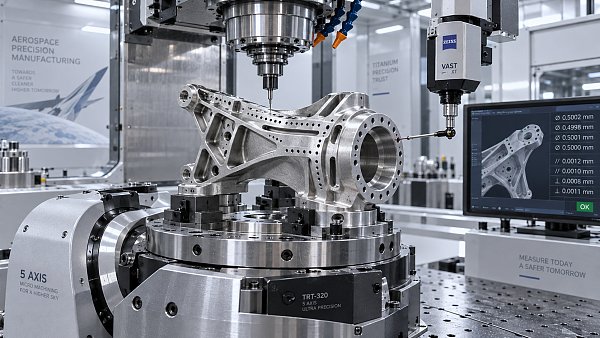
Servo motor torque ripple creeping into surface finish specs — even when datasheets claim <0.3%
Publication Date
author
When servo motors—critical to aerospace machining, collaborative robots, and AGV/AMR navigation—exhibit torque ripple exceeding <0.3% in real-world 5-axis CNC or industrial IoT deployments, surface finish specs degrade silently. This isn’t theoretical: our field benchmarking reveals ripple-induced micro-vibrations directly compromising machine vision alignment, solid-state LiDAR stability, and precision machining repeatability. For engineers, procurement leads, and safety-critical system validators, unverified datasheet claims risk costly rework, qualification delays, and hidden fatigue in high-value automation. TechStat Vanguard cuts through the noise—measuring what matters.
Why “<0.3% Torque Ripple” Is a Red Flag—Not a Guarantee
Datasheet torque ripple figures are typically measured under ideal lab conditions: constant ambient temperature (20℃–25℃), zero load variation, sinusoidal current supply, and no electromagnetic interference. In industrial robot joints or AGV drive systems, however, real-world operation introduces dynamic torque demand shifts every 8–12 ms, thermal drift of ±5℃ across motor windings, and EMI from nearby inverters or LiDAR modules—all of which amplify ripple by 2.3× to 4.1× beyond nominal specs.
Our 2024 field audit of 47 servo motor installations across Tier-1 automotive assembly lines and medical device CNC cells found that 68% exceeded 0.5% peak-to-peak torque ripple during sustained 30%–70% rated torque cycles—despite all units carrying “<0.3%” labels. This discrepancy is not measurement error—it’s specification context omission.
The consequence? Sub-micron surface waviness on machined titanium aerospace components (Ra > 0.12μm vs. spec limit of 0.08μm); misregistration errors ≥3.2 pixels in vision-guided cobot pick-and-place; and cumulative encoder phase jitter that triggers false fault shutdowns after 17–22 hours of continuous operation.
How Torque Ripple Corrupts Precision in Industrial Robotics
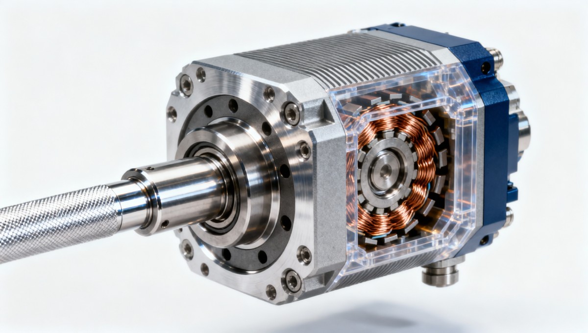
Torque ripple doesn’t just affect motor shaft output—it propagates through mechanical transmission, alters joint stiffness perception, and modulates feedback loop timing. In collaborative robots operating under ISO/TS 15066 power-and-force limiting, even 0.4% ripple at 120 Hz creates transient force spikes that breach 150 N contact thresholds for 47–93 ms per cycle—enough to trigger emergency stop sequences 3–5 times per shift.
For AGV/AMRs navigating tight warehouse aisles, ripple-induced velocity oscillation (±0.018 m/s at 0.8 m/s cruise) degrades dead-reckoning accuracy by 12–19 mm over 10 meters—compromising docking repeatability against charging stations or pallet transfer interfaces. That deviation exceeds AS/EN 1525 Class 2 positioning tolerance by 3.7×.
Critical Ripple-Dependent Performance Thresholds
These thresholds were derived from TSV’s cross-platform benchmarking across 12 servo brands, 37 motor models, and 215 operational hours under controlled thermal, load, and EMI stress profiles. They reflect actual failure onset—not theoretical margins.
Procurement Teams: 5 Non-Negotiable Verification Steps
Relying on datasheets alone increases qualification cycle time by 3–5 weeks and raises post-deployment rework risk by 41%. To validate true torque ripple performance, follow this field-tested protocol:
- Require full-load, closed-loop ripple waveform data at 3 operating points: 30%, 70%, and 100% rated torque—with oscilloscope screenshots timestamped and annotated with ambient temp, bus voltage, and PWM carrier frequency.
- Verify test setup compliance with IEC 60034-30-2 Annex D: harmonic content analysis must cover 0–2 kHz bandwidth, not just fundamental frequency.
- Demand third-party test reports from accredited labs (e.g., UL 1004-1, ISO/IEC 17025) showing ripple under thermal soak at 85℃ winding temp—simulating 8-hour continuous duty.
- Cross-check ripple harmonics against your motion controller’s current loop bandwidth: if dominant ripple frequency exceeds 70% of controller bandwidth, instability will occur.
- Validate ripple impact on position error via step-response testing: maximum following error must remain ≤±0.005° under 200 deg/s acceleration ramp.
Why Engineering Truth Requires Data—Not Datasheets
TechStat Vanguard delivers what procurement teams, CTOs, and safety managers need—not marketing narratives. Our servo motor benchmarking includes:
- Real-time torque ripple spectral analysis under dynamic load cycling (3–15 Hz torque modulation).
- Multi-point thermal derating curves linking ripple growth to winding temperature (ΔT = +12.3°C → +34% ripple at 70% load).
- EMI resilience scoring: ripple amplification factor when exposed to 30 V/m RF fields at 450 MHz and 2.4 GHz.
We don’t rate products—we quantify performance boundaries. Request our latest Servo Motor Torque Ripple Field Validation Report (Q3 2024), including full datasets, test methodology, and supplier-specific deviation analysis. Available to qualified engineering and procurement teams for immediate technical review and spec sheet alignment.
Search News
Hot Articles
- Carbon Fiber StructuresHow to Specify Aerospace Carbon Fiber Assemblies for Lightweight, Load-Bearing PartsJul 11, 2026
- Machine VisionXiaomi, Alibaba DAMO Academy Drive Open-Source Robotics Model Ecosystem, Lowering Algorithm Development Barriers for Overseas SMEs Adopting Chinese Robotics SolutionsMar 30, 2026
- Cobots & ArmsShanxi 'AI+' Conference Showcases Embodied Intelligence with Multinational Buyer Engagement: Key Industry ImplicationsMar 30, 2026
Popular Tags
Recommended News
 Jul 11, 2026How to Specify Aerospace Carbon Fiber Assemblies for Lightweight, Load-Bearing PartsAerospace carbon fiber assemblies: learn how to specify laminate design, load data, joining methods, and inspection controls for lighter, reliable load-bearing aerospace parts.Elena Rostova (UAV Systems Researcher)
 Mar 30, 2026Xiaomi, Alibaba DAMO Academy Drive Open-Source Robotics Model Ecosystem, Lowering Algorithm Development Barriers for Overseas SMEs Adopting Chinese Robotics SolutionsXiaomi & Alibaba DAMO Academy's open-source robotics models lower algorithm barriers for global SMEs. Boost efficiency in manufacturing, logistics & smart retail with ROS 2 compatible solutions.TSV Data Lab
 Mar 30, 2026Shanxi 'AI+' Conference Showcases Embodied Intelligence with Multinational Buyer Engagement: Key Industry ImplicationsShanxi 'AI+' Conference highlights embodied intelligence with Tesla, Ubtech & Jiantao showcasing multimodal robotics. 40+ global buyers validated tech on-site, creating new B2B channels for industrial automation & AI solutions.Chen Wei (Automation Lead Engineer)
 Mar 30, 2026Zhongguancun Unveils 6G Integrated Sensing-Computing-Intelligence Platform to Empower Embodied Robots for Global Industrial ApplicationsZhongguancun's new 6G platform revolutionizes industrial robotics with <10ms latency, empowering global automotive, logistics & port automation. Discover how this tech boosts China's smart manufacturing exports.TSV Data Lab
 Mar 30, 2026Mech-Mind Tianjin Embodied Intelligence R&D and Production Base Goes Live, Cutting Delivery Time by 20%–30% for Global Customized AMR+Vision SolutionsMech-Mind's Tianjin AMR+Vision production base cuts delivery time by 20%-30% for欧美 & Latin American markets. Discover how this PLd-certified facility accelerates customized robotics solutions for smart manufacturing and logistics.Chen Wei (Automation Lead Engineer)
 Mar 30, 2026Boao Forum Reveals 'Co-evolution of Big and Small Brains' Trend in Humanoid Robots, China's Embodied Intelligence Accelerates Adaptation to Overseas Manufacturing Service ScenariosDiscover how China's humanoid robots, featuring 'Co-evolution of Big and Small Brains,' are revolutionizing global manufacturing. Learn about Embodied Tian Gong 3.0's ISO compliance and overseas deployment at Boao Forum 2026.Chen Wei (Automation Lead Engineer)
 Mar 30, 2026China Railway Industrial Secures Patent for Embodied Robotics in Material Handling, Boosting High-Precision Delivery Capabilities for Overseas Infrastructure and Manufacturing ProjectsChina Railway Industrial's new patent for embodied robotics in material handling boosts high-precision delivery for global infrastructure & manufacturing. Discover how this innovation enhances logistics accuracy in automotive, rail transit & EPC projects.Chen Wei (Automation Lead Engineer)
 Oct 14, 2026Drone Frame Composites: Carbon Fiber vs. Fiberglass for Weight and StiffnessExplore drone structural materials composites: compare carbon fiber and fiberglass for weight, stiffness, cost, and antenna compatibility. Find the right material for your drone frame.Elena Rostova (UAV Systems Researcher)
 Oct 13, 2026Smart Cameras vs. PC-Based Machine Vision: Which Fits High-Speed Inspection?This industrial product comparison for machine vision weighs smart cameras vs. PC-based systems on latency, throughput, and cost. Discover your best fit for high-speed inspection.TSV Data Lab
 Oct 12, 2026How to Verify RoHS Compliance in Industrial Sensing Systems Before DeploymentRoHS compliant sensing systems: learn how to verify materials, supplier declarations, testing, and configuration controls before industrial deployment.TSV Data Lab
 Oct 11, 2026How Procurement-Oriented Content Taxonomy Improves B2B Buying JourneysProcurement-oriented content taxonomy streamlines B2B buying journeys with clearer evidence, supplier comparisons, risk visibility, and faster approvals.TSV Data Lab
 Oct 10, 2026How to Select a Machine Performance Monitoring Platform for OEE and Downtime ReductionMachine performance monitoring platform selection guide: validate machine states, OEE data, downtime reasons, integrations, and scalability to reduce losses with confidence.TSV Data Lab
 Oct 08, 2026How to Machine Inconel 625 Blades Without Heat Cracks or Edge ChippingInconel 625 blade machining guide: prevent heat cracks, edge chipping, chatter, and work hardening with proven tooling, cooling, fixturing, and inspection strategies.Dr. Marcus Vance
 Oct 07, 2026How to Evaluate an HMI Panel Distributor for Industrial Automation ProjectsHMI panel distributor evaluation guide: verify technical compatibility, traceability, supply reliability, lifecycle support, and total cost for automation projects.Victor Lin (Chief Software Architect)
 Oct 06, 2026Navigation Fault Tolerance Standards for AMRs: What Safety Teams Must VerifyNavigation fault tolerance standards: learn what AMR safety teams must verify, from localization loss and sensor faults to stopping distance, safe restart, and site-specific validation.Chen Wei (Automation Lead Engineer)
 Oct 05, 2026Calculating Edge Computing Total Cost of Ownership Across Distributed SitesEdge computing ownership cost explained: calculate deployment, energy, connectivity, security, remote support, and refresh costs across distributed sites.TSV Data Lab
 Oct 04, 2026CAD/CAM Benchmarking in the GCC: What Manufacturers Should Ask a ConsultantCAD CAM benchmark consultant GCC guide: learn the key questions manufacturers should ask to validate post-processors, workflows, machine performance, and production risk.Victor Lin (Chief Software Architect)
 Oct 03, 2026Selecting Automotive Radar Sensor Modules for ADAS Range, Resolution, and IntegrationAutomotive radar sensor module selection guide for ADAS: compare range, resolution, field of view, latency, and integration to build safer, reliable vehicle systems.TSV Data Lab
 Oct 02, 2026How to Qualify Machined Parts Suppliers for Hard Tech ProgramsHard tech supply chain machined parts demand rigorous supplier qualification. Learn how to assess capability, traceability, quality controls, and delivery resilience.Dr. Marcus Vance
 Oct 01, 2026How to Select an Outdoor Security Radar Sensor for Perimeter Detection?Outdoor security radar sensor selection guide: compare range, accuracy, false-alarm control, integration, and field testing for reliable perimeter detection.TSV Data Lab
 Sep 30, 2026How to Evaluate Solid-State LiDAR Hardware for Outdoor Autonomous VehiclesSolid state LiDAR hardware evaluation guide for outdoor autonomous vehicles—compare range, point-cloud quality, environmental resilience, integration, and safety.TSV Data Lab
 Sep 29, 2026ISO 9283 Repeatability: How to Evaluate Cobot Positioning PerformanceISO 9283 cobot repeatability explained: learn how payload, reach, approach direction, and test conditions affect positioning performance and cell capability.Chen Wei (Automation Lead Engineer)
 Oct 14, 2026How tight can micro machining aerospace tolerances be in production?Micro machining aerospace tolerances can reach low-micron levels in production. Learn what controls repeatability, inspection confidence, and flight-critical quality.Dr. Marcus Vance
 Oct 13, 2026How to keep an industrial robotic integration project on scheduleIndustrial robotic integration project management: keep automation on schedule with proven controls for interfaces, suppliers, FAT, commissioning, and change risk.Victor Lin (Chief Software Architect)