PEEK CNC machining service problems caused by heat buildup
Publication Date
author
Heat buildup is one of the most overlooked causes of failure in PEEK CNC machining service, directly affecting dimensional stability, burr formation, and surface quality. For engineers, buyers, and production teams comparing micro machining tolerance limits, 5 axis CNC surface finish Ra, or medical grade PEEK sterilization test requirements, understanding thermal risk is essential before approving any high-precision part.
Why heat buildup becomes a hidden failure point in PEEK CNC machining service
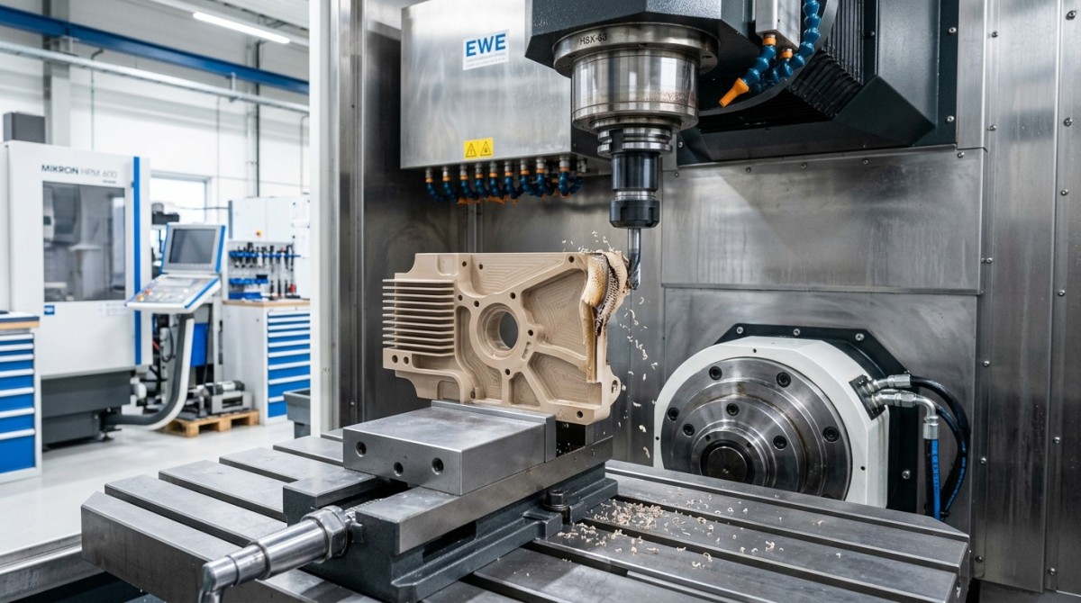
PEEK is valued for chemical resistance, mechanical strength, sterilization compatibility, and stable performance in demanding sectors such as medical devices, aerospace systems, electronics, and precision industrial assemblies. Yet those same advantages often create false confidence during machining. Unlike common metals, PEEK reacts to cutting heat through softening, localized deformation, and stress release rather than obvious burning alone.
In practical PEEK CNC machining service workflows, thermal problems usually appear when spindle speed, feed rate, tool sharpness, and chip evacuation are not balanced. The issue is not just peak temperature. It is also heat concentration over time, especially in thin walls, deep pockets, micro holes, and high-aspect-ratio features where chips remain in contact for too long. Even a small thermal drift can push tolerance from ±0.02 mm toward an unacceptable range.
For information researchers, the first key judgment is simple: if a supplier only discusses material grade but not thermal control strategy, process capability remains incomplete. For operators, the concern is whether the process can maintain repeatability over a 2-hour to 6-hour batch. For procurement teams and business decision-makers, the real risk is hidden scrap, rework delay, and validation failure after delivery.
TSV’s engineering-first perspective is especially useful here. Instead of marketing phrases, the evaluation should focus on measurable process variables: cutting zone heat, chip color, burr tendency, post-machining warp, Ra variation, and batch consistency across 10, 50, or 200 parts. Parameters do not lie, and thermal behavior is one of the clearest examples.
Where the heat usually comes from
Most heat buildup in PEEK CNC machining service is generated by four linked sources rather than one isolated mistake. High spindle speed can create friction. Low feed per tooth can cause rubbing instead of cutting. Dull tooling raises contact time. Poor evacuation keeps chips recirculating and reheating the workpiece. These factors often compound each other within the same operation.
- Rubbing at the tool edge when feed is too conservative for the tool diameter and flute geometry.
- Chip packing in slots, blind cavities, or micro features, especially when compressed air or vacuum extraction is insufficient.
- Long tool overhang that introduces vibration, recutting, and uneven heat distribution on the feature wall.
- Aggressive finishing passes that look light on paper but generate continuous surface friction during 3-axis or 5-axis contouring.
A reliable supplier should be able to explain which of these heat sources is dominant for your part geometry. That level of explanation is often more useful than broad promises about “high precision machining.”
What thermal damage looks like on real parts and how to judge severity
Heat damage in PEEK CNC machining service does not always look dramatic. In many cases, the part leaves the machine appearing acceptable, only to fail later in dimensional inspection, mating assembly, leak testing, or sterilization validation. This is why thermal risk should be reviewed from both visible and latent defect perspectives.
For operators, visible warning signs include smeared edges, stringy burrs, glossy patches from localized melting, and chips that look welded or flattened rather than crisp. For quality teams, the more serious signs are feature drift after 12 to 24 hours, hole size instability, flatness loss on thin sections, and changing surface roughness from one cavity region to another.
For buyers comparing quotations, thermal defects matter because they often sit outside a simple piece-price discussion. A lower quote may exclude process validation, first article review, or thermal-risk mitigation steps. That can increase the true landed cost when parts require secondary deburring, manual straightening, or partial remanufacture.
The table below helps translate thermal symptoms into purchasing and process decisions. It is useful when reviewing supplier capability for medical grade PEEK, aerospace brackets, electrical insulators, and micro precision components.
A useful interpretation rule is this: if the defect changes geometry, function, or long-term dimensional stability, it is not merely a cosmetic issue. It is a process capability issue. That distinction matters during supplier qualification and PPAP-like review stages, even where formal automotive documentation is not required.
Which parts are most vulnerable
The highest-risk PEEK parts are usually not the largest ones. Thermal sensitivity increases in micro features, wall sections below roughly 1.5 mm to 2.0 mm, deep ribs, high cavity density layouts, and parts requiring tight surface finish or sealing contact. Components with both thin geometry and tolerance expectations tighter than ±0.03 mm deserve extra scrutiny before order release.
Medical and analytical equipment parts create another challenge. Some parts may pass incoming inspection but later enter sterilization or thermal cycling, where internal stress becomes visible. That is why it is wise to ask whether the machining route considered post-process conditioning, stabilization time, or inspection after a rest period rather than immediate measurement only.
How engineers and buyers should evaluate thermal control before placing an order
When selecting a PEEK CNC machining service partner, thermal control should be treated as a procurement criterion, not only a shop-floor concern. A quote can look competitive while hiding risk in tooling strategy, inspection timing, or process discipline. For this reason, buyers should request technical answers that reveal whether the supplier understands polymer machining rather than metal habits transferred onto plastic.
At minimum, decision-makers should review 5 core areas: material state, tool condition, chip evacuation, tolerance plan, and final inspection sequence. If the part has demanding requirements such as Ra targets, micro holes, or multi-axis contouring, add a sixth area: thermal load management during finishing. This is especially important for 5 axis CNC surface finish Ra assessments where geometry changes tool engagement continuously.
The next table is designed as a supplier screening tool. It can be used by R&D engineers, sourcing teams, and plant managers during RFQ comparison, technical review, or pilot batch approval.
If a supplier can answer these questions clearly, the discussion immediately moves from generic capability to evidence-based capability. That aligns with TSV’s data-driven approach: procurement quality improves when selection criteria are measurable and connected to actual failure modes.
A 4-step review process before PO release
- Confirm feature criticality: identify sealing faces, press-fit holes, thin walls, and cosmetic surfaces that cannot tolerate thermal deformation.
- Request process notes: ask how roughing, semi-finishing, and finishing are separated to reduce heat concentration.
- Define inspection window: specify whether critical dimensions require post-cooling or delayed verification after 12–24 hours.
- Validate with samples: for new geometry, approve a small batch of 3–10 parts before scaling to medium or large production.
This 4-step review is simple, but it catches many hidden risks early. It also shortens the supplier qualification cycle because the discussion centers on evidence instead of vague capability claims.
Process decisions that reduce heat buildup without sacrificing precision
Reducing heat in PEEK CNC machining service is not about using the slowest possible parameters. In fact, overly conservative settings can worsen the problem by increasing rubbing time. The target is controlled chip formation, stable evacuation, and low dwell. That means the process window must be tuned for geometry, toolpath, and required finish rather than copied from a generic plastic chart.
For high-precision parts, shops often separate the route into 3 stages: roughing for material removal, intermediate relief or stabilization, and light finishing after temperature normalization. This staged method is especially relevant when flatness, concentricity, or sealing integrity matters. On complex 5-axis parts, careful tool engagement control can reduce heat spikes on corners and steep walls.
Cooling strategy should also be selected carefully. Flood coolant is not always the default answer in polymer machining. Depending on part design and cleanliness requirements, dry machining with controlled air blast, mist, or vacuum extraction may be preferable. The correct choice depends on contamination risk, chip shape, and whether the application falls under medical, semiconductor, or high-cleanliness assembly conditions.
Below is a practical comparison of common thermal-control methods used in precision machining decisions. The best route depends on part value, cleanliness needs, and target tolerance band.
Comparison of control methods
From a cost perspective, these measures may add process time, but they usually reduce total project risk. One extra inspection cycle or one added stabilization step is often cheaper than a failed pilot build or delayed device validation.
What operators should monitor during production
- Chip shape and color consistency across the first 5–10 parts of a run.
- Surface gloss change, edge softening, or burr growth during long-cycle machining.
- Feature drift between in-process checks and final room-temperature inspection.
- Tool wear progression, especially where one worn cutter can affect an entire batch of 20, 50, or more parts.
These shop-floor observations sound basic, but they connect directly to the commercial outcome. Better thermal monitoring means fewer hidden defects, fewer disputes over acceptance, and more predictable delivery.
Standards, validation, and common misunderstandings in high-spec PEEK parts
In regulated or high-consequence applications, the machining process cannot be separated from compliance expectations. A supplier may not need to claim every formal certification to be useful, but they should understand how machining behavior influences downstream verification under frameworks such as ISO 13485-related medical workflows or AS9100-oriented aerospace quality expectations. The exact requirement depends on the project, yet thermal stability remains relevant across both.
One common misunderstanding is that PEEK’s high service temperature means machining heat is rarely a problem. That assumption is incorrect. Service temperature performance and cutting-zone behavior are different engineering questions. Machining introduces friction, local stress, and transient softening at the tool-work interface. A material can perform well in service yet still deform during poor machining conditions.
Another misunderstanding is that tighter tolerance alone proves better machining. In reality, a drawing callout such as ±0.01 mm only has value if the supplier can maintain it after cooling, handling, cleaning, and shipment. For critical parts, it is reasonable to define 3 linked acceptance points: immediate post-machining review, stabilized dimensional check, and final outgoing inspection.
TSV’s broader hard-tech perspective matters here because precision machining sits inside a larger supply-chain decision. The right partner is not simply the one that can machine PEEK. It is the one that can explain parameter logic, inspection timing, document assumptions, and support engineering decisions with traceable technical language.
FAQ for research, procurement, and production teams
How should I compare suppliers for micro machining tolerance limits?
Do not compare only the quoted tolerance number. Ask how the number is verified, at what temperature state, after what waiting period, and on which measurement method. For micro features, a supplier that can explain inspection after thermal stabilization is often a safer choice than one that only advertises a tight nominal figure.
Can a good surface finish still hide thermal damage?
Yes. A visually smooth surface may still contain heat-related distortion, edge softness, or unstable geometry. This is especially true for thin sections and cosmetic parts. Surface finish Ra should be reviewed together with flatness, hole position, and batch repeatability, not as an isolated acceptance metric.
What is a realistic lead-time impact when thermal control is handled properly?
For standard prototype work, proper thermal management may add little or no delay if the shop already has a stable process. For critical parts, staged machining, sample validation, or delayed inspection can extend lead time by about 1–3 days. In most B2B programs, that is a reasonable trade for lower scrap and fewer qualification failures.
Is medical grade PEEK automatically harder to machine?
Not automatically, but the project usually has stricter cleanliness, traceability, and validation expectations. That raises the importance of thermal control because post-machining distortion, burrs, or contamination can affect not only dimensions but also documentation, cleaning steps, and downstream compliance review.
Why a data-driven technical partner reduces sourcing risk
In a noisy supply market, the real challenge is not finding a vendor that claims to machine PEEK. The challenge is identifying a partner that can translate drawing requirements into a thermally stable process, realistic lead time, and defensible inspection plan. That is exactly where data-driven evaluation has more value than promotional language.
TechStat Vanguard focuses on engineering truth through data. For precision machining decisions, that means framing supplier discussions around tolerance windows, finish consistency, inspection timing, process traceability, and application-specific risk. Whether your team works in medical, aerospace, automation, electronics, or mixed industrial programs, this approach helps reduce R&D trial-and-error costs and shortens supplier qualification cycles.
If you are reviewing a PEEK CNC machining service for a new part or a supplier transfer, contact us with the details that actually matter: target tolerance, wall thickness, Ra requirement, annual volume, drawing revision, material grade, sterilization or cleanliness expectations, and expected delivery window. We can help you structure a more rigorous technical review before quotation approval.
You can also reach out for parameter confirmation, supplier comparison logic, prototype-to-production risk review, sample strategy, certification-related discussion, or lead-time planning. When the requirement is precise, the decision should be precise as well. In hard-tech sourcing, better questions are often the fastest path to better parts.
Search News
Hot Articles
- Carbon Fiber StructuresHow to Specify Aerospace Carbon Fiber Assemblies for Lightweight, Load-Bearing PartsJul 11, 2026
- Machine VisionXiaomi, Alibaba DAMO Academy Drive Open-Source Robotics Model Ecosystem, Lowering Algorithm Development Barriers for Overseas SMEs Adopting Chinese Robotics SolutionsMar 30, 2026
- Cobots & ArmsShanxi 'AI+' Conference Showcases Embodied Intelligence with Multinational Buyer Engagement: Key Industry ImplicationsMar 30, 2026
Popular Tags
Recommended News
 Jul 11, 2026How to Specify Aerospace Carbon Fiber Assemblies for Lightweight, Load-Bearing PartsAerospace carbon fiber assemblies: learn how to specify laminate design, load data, joining methods, and inspection controls for lighter, reliable load-bearing aerospace parts.Elena Rostova (UAV Systems Researcher)
 Mar 30, 2026Xiaomi, Alibaba DAMO Academy Drive Open-Source Robotics Model Ecosystem, Lowering Algorithm Development Barriers for Overseas SMEs Adopting Chinese Robotics SolutionsXiaomi & Alibaba DAMO Academy's open-source robotics models lower algorithm barriers for global SMEs. Boost efficiency in manufacturing, logistics & smart retail with ROS 2 compatible solutions.TSV Data Lab
 Mar 30, 2026Shanxi 'AI+' Conference Showcases Embodied Intelligence with Multinational Buyer Engagement: Key Industry ImplicationsShanxi 'AI+' Conference highlights embodied intelligence with Tesla, Ubtech & Jiantao showcasing multimodal robotics. 40+ global buyers validated tech on-site, creating new B2B channels for industrial automation & AI solutions.Chen Wei (Automation Lead Engineer)
 Mar 30, 2026Zhongguancun Unveils 6G Integrated Sensing-Computing-Intelligence Platform to Empower Embodied Robots for Global Industrial ApplicationsZhongguancun's new 6G platform revolutionizes industrial robotics with <10ms latency, empowering global automotive, logistics & port automation. Discover how this tech boosts China's smart manufacturing exports.TSV Data Lab
 Mar 30, 2026Mech-Mind Tianjin Embodied Intelligence R&D and Production Base Goes Live, Cutting Delivery Time by 20%–30% for Global Customized AMR+Vision SolutionsMech-Mind's Tianjin AMR+Vision production base cuts delivery time by 20%-30% for欧美 & Latin American markets. Discover how this PLd-certified facility accelerates customized robotics solutions for smart manufacturing and logistics.Chen Wei (Automation Lead Engineer)
 Mar 30, 2026Boao Forum Reveals 'Co-evolution of Big and Small Brains' Trend in Humanoid Robots, China's Embodied Intelligence Accelerates Adaptation to Overseas Manufacturing Service ScenariosDiscover how China's humanoid robots, featuring 'Co-evolution of Big and Small Brains,' are revolutionizing global manufacturing. Learn about Embodied Tian Gong 3.0's ISO compliance and overseas deployment at Boao Forum 2026.Chen Wei (Automation Lead Engineer)
 Mar 30, 2026China Railway Industrial Secures Patent for Embodied Robotics in Material Handling, Boosting High-Precision Delivery Capabilities for Overseas Infrastructure and Manufacturing ProjectsChina Railway Industrial's new patent for embodied robotics in material handling boosts high-precision delivery for global infrastructure & manufacturing. Discover how this innovation enhances logistics accuracy in automotive, rail transit & EPC projects.Chen Wei (Automation Lead Engineer)
 Oct 27, 2026GXO and Agility Robotics Expand Partnership to Accelerate US Humanoid Robot DeploymentGXO and Agility Robotics plan to expand US humanoid robot deployment with Digit 4 in early 2027. Explore warehouse automation plans, service terms and future Digit 5 upgrades.Chen Wei (Automation Lead Engineer)
 Oct 27, 2026Robotic Automation Costs: Budgeting for Equipment, Integration, and MaintenancePlan your robotics automation cost with confidence. Explore equipment, integration, and maintenance expenses, compare quotes, and build a realistic budget for better ROI.Chen Wei (Automation Lead Engineer)
 Oct 26, 2026AMAXiMAL Releases Open-Source TopMod 3D v3 With Claude AIExplore AMAXiMAL’s free, open-source TopMod 3D v3 with Claude AI assistance, topology-based modeling and plywood fabrication tools that connect complex designs to physical builds.Dr. Marcus Vance
 Oct 26, 2026Choosing a SCADA System Integrator Company: PLC Compatibility and Long-Term SupportChoose a scada system integrator company with proven PLC compatibility and reliable long-term support. Discover what to test, compare, and require before investing.Victor Lin (Chief Software Architect)
 Oct 25, 2026Hesai Leads Global ADAS Main Lidar Shipments in Yole’s 2026 ReportHesai led global ADAS main lidar shipments with a 43% share in 2025, according to Yole’s 2026 report. Explore what this ranking reveals about its automotive market position.TSV Data Lab
 Oct 25, 2026Choosing an Aerospace Materials Manufacturer: Quality and Traceability ChecksChoosing an aerospace materials manufacturer? Learn how to verify certifications, test reports, and lot traceability to qualify suppliers confidently and reduce costly sourcing risks.Dr. Marcus Vance
 Oct 24, 2026Guotai Haitong: Global Entry-Level 3D Printer Shipments Rose 39% in Q1 2026Entry-level 3D printer shipments rose 39% in Q1 2026, Guotai Haitong reports. Explore how AI, multicolor printing and print farms are shaping market growth.Dr. Marcus Vance
 Oct 24, 2026Choosing an Industrial Vision Inspection Supplier: Acceptance Tests That MatterChoose an industrial vision inspection supplier with confidence. Discover acceptance tests for defect detection, false rejects, production speed, and reliable part rejection before you buy.TSV Data Lab
 Oct 23, 2026US Navy Raises Gecko Robotics Contract Ceiling to $300M for Robotic Fleet MaintenanceUS Navy raises Gecko Robotics’ contract ceiling to $300M for Pacific Fleet robotic inspections. Explore potential opportunities for maintenance suppliers and key procurement considerations.Chen Wei (Automation Lead Engineer)
 Oct 23, 2026Choosing Industrial Sensing Systems for Global Plants: Protocol CompatibilityCompare industrial sensing systems international buyers can trust. Explore protocol compatibility, reduce integration risks, and select proven configurations for reliable global plant deployments.TSV Data Lab
 Oct 22, 2026KUKA Showcases Physical AI and iiQKA.AI Vision at NVIDIA GTC BerlinExplore KUKA’s Physical AI showcase at NVIDIA GTC Berlin and discover how iiQKA.AI Vision aims to simplify robotic vision integration and improve 2D and 3D scene recognition.TSV Data Lab
 Oct 22, 2026Robotic Machining of Advanced Composites: What Tolerances Are Achievable?Explore advanced materials machining robotics: discover what drives achievable composite tolerances and how to validate accuracy before investing in your next machining system.Dr. Marcus Vance
 Oct 21, 2026China’s Industrial Robot Exports Near RMB 10 Billion in First Nine Months of 2026China’s industrial robot exports neared RMB 10 billion in January–September 2026, with value rising faster than volume. Explore the data and what it could mean for suppliers.Chen Wei (Automation Lead Engineer)
 Oct 21, 2026Low-Latency Industrial Data Processing: Pricing and Key Cost DriversExplore industrial data latency price drivers, from edge hardware to integration and support. Learn how to compare quotes, verify performance, and avoid unnecessary costs.TSV Data Lab
 Oct 20, 2026KUKA Launches iiQKA.AI Vision to Simplify Industrial Image ProcessingKUKA iiQKA.AI Vision simplifies industrial image processing with controller-based 2D and 3D vision. Explore drag-and-drop setup for vision-guided automation.TSV Data Lab
 Oct 20, 2026Smart Industrial Edge Devices: Key Criteria for Legacy PLC IntegrationChoose smart industrial edge devices for legacy PLC integration. Discover key criteria for compatibility, data quality, security, and reliable collection without disrupting control.TSV Data Lab
 Oct 19, 2026Choosing a Radar Sensor by Application: Range, Resolution, and Field of ViewSimplify radar sensor application based product selection. Compare range, resolution, and field of view to avoid blind spots and choose with confidence. Explore the guide.TSV Data Lab