
CNC milling for automotive engine blocks and flatness control
Publication Date
author
In cnc milling for automotive engine blocks, flatness control is not just a machining target—it is a critical quality and safety variable that affects sealing performance, thermal stability, and downstream assembly reliability. For quality and safety managers, understanding how process parameters, fixturing, tool wear, and inspection data interact is essential to reducing defects, controlling risk, and maintaining consistent production standards.
For most searchers evaluating cnc milling for automotive engine blocks, the real question is not simply how milling works. It is how to keep deck surfaces, joint faces, and reference planes consistently flat within specification under real production conditions, where heat, clamping distortion, machine variation, insert wear, and measurement error can all turn a nominally capable process into a recurring source of leaks, scrap, and customer complaints.
From a quality and safety standpoint, the overall judgment is clear: flatness problems in engine block milling are rarely caused by one isolated variable. They usually come from a chain of interacting factors across machining strategy, workholding, thermal control, tool condition, machine geometry, material behavior, and inspection discipline. The plants that control flatness best are the ones that manage the full process window with data, not those that only react after out-of-spec parts appear.
Why flatness control in engine block milling matters more than many teams assume
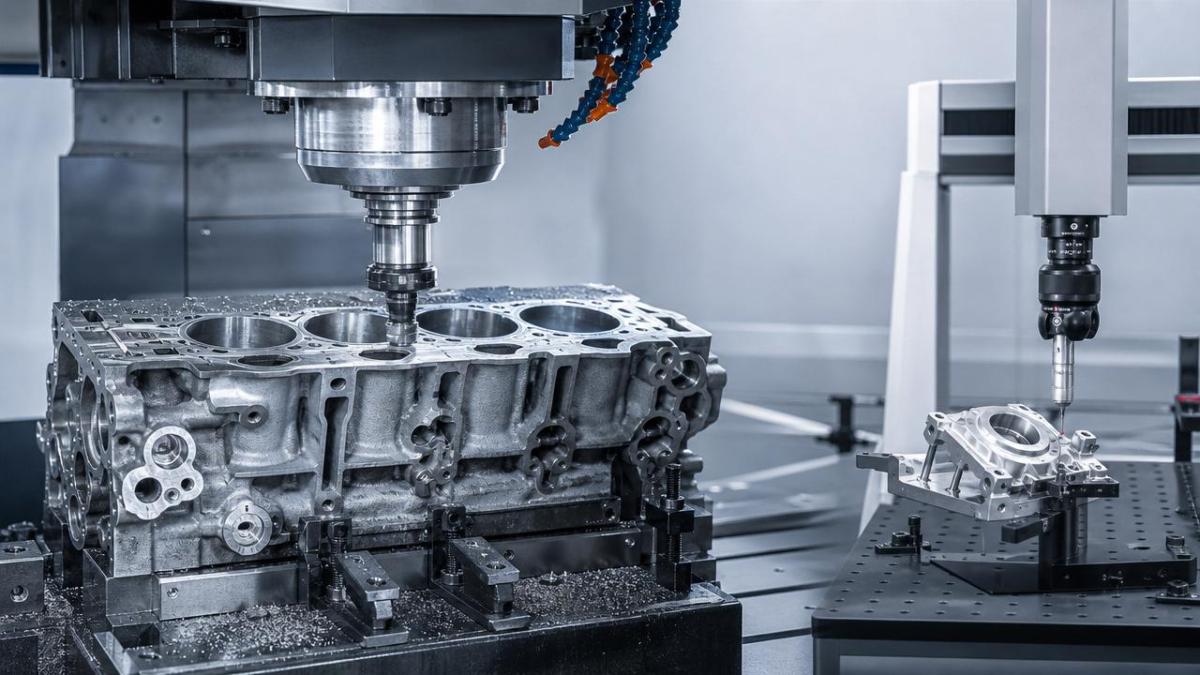
In automotive powertrain manufacturing, a flat engine block surface is directly tied to gasket sealing, head-to-block contact integrity, bolt load distribution, and fluid containment. If the deck face is not flat enough, even a small deviation can increase the chance of head gasket leakage, oil seepage, coolant loss, and localized thermal stress during service.
For quality personnel, this means flatness is not merely a dimensional acceptance item on a drawing. It is a functional quality characteristic. For safety managers, it is also a risk signal, because sealing failure in an engine assembly may escalate into overheating, lubricant contamination, field failures, warranty exposure, or in severe cases, vehicle safety concerns related to engine performance degradation.
That is why cnc milling for automotive engine blocks must be evaluated not only by cycle time or metal removal rate, but by whether the process can repeatedly deliver stable flatness under normal and worst-case operating conditions. A process that looks efficient on paper but drifts with tool wear or temperature change is not a robust process.
What quality and safety managers usually need to know first
The first concern is process capability. Can the machining line hold flatness consistently across shifts, batches, operators, and machine states? A single acceptable sample part proves very little. The more important question is whether the process remains centered over time and whether variation stays far enough away from the specification limit to avoid hidden risk.
The second concern is failure mode visibility. When flatness goes out of control, how quickly can the team detect it, isolate the source, and contain affected parts? In many facilities, measurement exists, but the reaction plan is weak. That creates a dangerous delay between process drift and corrective action.
The third concern is cost of instability. Poor flatness control affects more than scrap. It increases rework, machine downtime, gauge disputes, supplier escalation, assembly line interruption, and customer trust erosion. In high-volume automotive environments, even a small rise in deck face nonconformance can rapidly become a major operational and financial issue.
Where flatness errors in cnc milling for automotive engine blocks actually come from
Flatness deviation usually has multiple root causes. One common source is clamping distortion. Engine blocks are large, complex castings with internal cavities and non-uniform wall sections. If the part is overconstrained or clamped unevenly, the block may deform during machining and then relax after unclamping, creating a false appearance of process inaccuracy when the real issue is fixture-induced stress.
Another frequent cause is thermal variation. Heat enters the system from spindle operation, cutting action, coolant behavior, ambient changes, and the casting itself. If the machine structure, fixture, tool, and workpiece are not in thermal balance, the surface generated during cutting may not reflect the geometry measured later at inspection.
Tool wear is equally critical. As inserts wear, cutting forces rise, chip formation changes, and the probability of surface waviness or localized height variation increases. Tool wear may also shift the effective cutting diameter or create inconsistent contact from one insert pocket to another on a face mill. When teams focus only on catastrophic tool failure, they often miss the gradual wear stage where flatness starts drifting before visible surface damage appears.
Machine tool condition must also be considered. Spindle runout, axis squareness error, guideway wear, backlash, poor leveling, and vibration can all influence surface generation. A machine may still produce acceptable dimensions on simpler features while quietly losing capability on a large, critical planar face.
Material behavior adds another layer. Cast iron and aluminum engine blocks respond differently to cutting forces, heat, and residual stress release. Castings with variable hardness, porosity zones, or unstable stock allowance can make flatness harder to hold unless the process window has enough margin.
How machining strategy influences flatness outcomes
Not all face milling strategies produce the same flatness stability. The choice of cutter diameter, insert geometry, lead angle, feed per tooth, cutting speed, axial depth, and radial engagement all affect cutting force direction and thermal load. For critical deck surfaces, a strategy optimized only for productivity may push forces too high and amplify part deflection or machine vibration.
Entry and exit behavior matter as well. Interrupted cutting across ports, bores, and cavities can create force fluctuation, especially in engine blocks with complex top-face geometry. If the cutter path repeatedly crosses unsupported areas or if insert engagement is poorly balanced, local distortion and waviness can develop even when average flatness appears close to target.
Some manufacturers improve control by separating roughing and finishing more carefully, leaving a stable and uniform finishing allowance. Others reduce variation by using a dedicated finishing pass under tightly controlled spindle and feed conditions rather than trying to combine aggressive stock removal with final surface generation in one operation.
From a quality perspective, the key is to verify whether the selected machining strategy is robust across the full tool life, not just at the start of a fresh insert set. A face milling program that holds flatness for the first 20 parts but drifts after 80 parts is not a stable production strategy.
Why fixturing often determines whether the process is truly controllable
In cnc milling for automotive engine blocks, fixturing is one of the strongest predictors of flatness performance. The fixture must locate the block repeatably while minimizing elastic distortion. If support points are poorly distributed, if locating datums do not reflect the functional part geometry, or if hydraulic clamping pressure varies, the machined surface can shift from part to part even when the machine and program remain unchanged.
For quality and safety managers, fixture review should include three questions. First, does the clamping scheme simulate the part’s natural supported state or force it into an artificial shape? Second, is the support system stable enough to absorb casting variation without overloading local regions? Third, are fixture wear and contamination monitored before they become hidden sources of error?
Good fixture design also supports better root cause analysis. When support, locating, and clamping logic are documented clearly, engineers can separate fixture-related distortion from machine or tooling problems much faster. Without that clarity, flatness issues often generate long debates but slow resolution.
How to monitor tool wear before it becomes a quality escape
Tool wear should be treated as a process variable, not a maintenance afterthought. The practical goal is to define the wear point where flatness capability begins to deteriorate, then replace or index inserts before that threshold is crossed. This is more effective than relying on fixed tool life rules that were never validated against functional flatness results.
Useful indicators include spindle load trend, surface roughness shift, cutting sound changes, burr formation, temperature rise, and increasing correction frequency in in-process offsets. However, none of these signals should stand alone. The best systems correlate wear indicators with actual flatness measurement data so the replacement rule reflects real process behavior.
Where production volume is high, statistical tracking of parts per edge, wear pattern by insert position, and flatness drift over tool life can reveal whether a specific insert pocket, cutter body, or operating condition is driving instability. That level of analysis is especially valuable in automotive environments where small recurring deviations can affect thousands of parts.
Inspection strategy: measuring flatness correctly is part of controlling it
Many flatness problems are made worse by weak measurement systems. If the gauge method is inconsistent, the team may chase machining changes for what is actually an inspection issue. For engine blocks, measurement strategy should match function, tolerance severity, production speed, and reaction needs.
Coordinate measuring machines, precision granite setups, laser scanning systems, and in-machine probing each offer advantages, but they also have limitations. The important point is not simply selecting a device. It is building a measurement system with known repeatability, reproducibility, datum consistency, environmental control, and clear decision rules.
Quality managers should insist on a robust measurement system analysis for critical flatness features. If repeatability and reproducibility consume too much of the tolerance, process decisions become unreliable. In that situation, the plant may either overreact and scrap good parts or underreact and pass bad ones downstream.
Sampling frequency also matters. If flatness is checked too infrequently, the line may produce a large batch of suspect engine blocks before drift is detected. If checked intelligently with risk-based intervals tied to tool life, machine state, and historical stability, inspection can act as an early warning system rather than a delayed audit.
What process capability and control plans should look like for critical engine block surfaces
For a critical feature such as an engine block deck, a capable quality plan should define more than the final tolerance. It should include the control method, sampling plan, gauge type, machine conditions, tool life limit, fixture verification interval, coolant condition checks, escalation triggers, and containment procedure when abnormal trends appear.
Process capability targets should reflect the business and safety risk of failure. If the feature is highly sensitive to sealing performance, relying on borderline capability is not enough. The process should run with adequate margin so normal variation, operator change, or environmental fluctuation does not push output toward the limit.
Control charts are especially useful when applied correctly. Monitoring mean shift and variation growth helps teams act before nonconformance occurs. A slow drift in flatness trend is often the earliest visible sign of insert wear, thermal instability, or fixture degradation. Waiting for an out-of-spec result wastes the predictive value of the data.
For safety-oriented organizations, reaction plans must also be specific. Who stops the line? Who reviews suspect inventory? How are downstream assemblies identified? What is the decision tree for rework, reinspection, and customer notification if necessary? A good control plan reduces ambiguity during a quality event.
Common warning signs that the milling process is becoming unsafe or unstable
There are several early indicators that cnc milling for automotive engine blocks may be losing flatness control. One is a gradual increase in corrective offset changes by operators. Another is recurring disagreement between in-process measurement and final CMM results. A third is unexplained variation by machine, shift, or casting lot.
Additional warning signs include a rise in head gasket leak test failures, localized witness marks on deck surfaces, changing spindle load patterns, abnormal insert wear distribution, and more frequent part seating issues in downstream assembly. None of these signs alone proves the root cause, but together they often point to a process that is becoming less predictable.
Quality and safety teams should not treat these signals as isolated shop floor noise. They are often the practical evidence that the process window is narrowing. Acting early is almost always less costly than containing a field-related issue later.
How suppliers and internal teams can prove they really control flatness
Claims about precision mean little without evidence. For buyers, auditors, and plant quality leaders, the most credible proof is a data package that links specification, process settings, capability study, tool life behavior, fixture logic, gauge validation, and ongoing statistical performance.
A mature supplier or internal machining team should be able to show how flatness was developed during process validation, what variables were tested, what the worst-case conditions are, and how production monitoring prevents drift. They should also be transparent about the measurement method and the threshold for intervention.
This evidence-based approach aligns with a broader engineering reality: reliable manufacturing is built on parameter discipline, not marketing language. In a critical component like an engine block, the strongest sign of competence is not a vague promise of quality. It is a demonstrated ability to control variation and explain why the process stays stable.
Conclusion: flatness control is a system discipline, not a single machining setting
For quality control and safety management professionals, the key takeaway is simple. Flatness in cnc milling for automotive engine blocks should be treated as a high-impact process characteristic with direct implications for sealing reliability, thermal behavior, assembly performance, and product risk.
The most effective plants do not search for one perfect spindle speed or one perfect inspection point. They build a controlled system: stable fixturing, validated machining strategy, disciplined tool wear management, reliable measurement, and fast reaction to trend changes. That system view is what turns flatness from a recurring defect source into a controlled manufacturing outcome.
If your goal is fewer leaks, fewer escapes, more predictable audits, and stronger supplier or internal process qualification, start by asking a harder question: not whether the engine block can be milled flat once, but whether the full process can prove it will stay flat every day, across the entire production window.
Search News
Hot Articles
- Carbon Fiber StructuresHow to Specify Aerospace Carbon Fiber Assemblies for Lightweight, Load-Bearing PartsJul 11, 2026
- Machine VisionXiaomi, Alibaba DAMO Academy Drive Open-Source Robotics Model Ecosystem, Lowering Algorithm Development Barriers for Overseas SMEs Adopting Chinese Robotics SolutionsMar 30, 2026
- Cobots & ArmsShanxi 'AI+' Conference Showcases Embodied Intelligence with Multinational Buyer Engagement: Key Industry ImplicationsMar 30, 2026
Popular Tags
Recommended News
 Jul 11, 2026How to Specify Aerospace Carbon Fiber Assemblies for Lightweight, Load-Bearing PartsAerospace carbon fiber assemblies: learn how to specify laminate design, load data, joining methods, and inspection controls for lighter, reliable load-bearing aerospace parts.Elena Rostova (UAV Systems Researcher)
 Mar 30, 2026Xiaomi, Alibaba DAMO Academy Drive Open-Source Robotics Model Ecosystem, Lowering Algorithm Development Barriers for Overseas SMEs Adopting Chinese Robotics SolutionsXiaomi & Alibaba DAMO Academy's open-source robotics models lower algorithm barriers for global SMEs. Boost efficiency in manufacturing, logistics & smart retail with ROS 2 compatible solutions.TSV Data Lab
 Mar 30, 2026Shanxi 'AI+' Conference Showcases Embodied Intelligence with Multinational Buyer Engagement: Key Industry ImplicationsShanxi 'AI+' Conference highlights embodied intelligence with Tesla, Ubtech & Jiantao showcasing multimodal robotics. 40+ global buyers validated tech on-site, creating new B2B channels for industrial automation & AI solutions.Chen Wei (Automation Lead Engineer)
 Mar 30, 2026Zhongguancun Unveils 6G Integrated Sensing-Computing-Intelligence Platform to Empower Embodied Robots for Global Industrial ApplicationsZhongguancun's new 6G platform revolutionizes industrial robotics with <10ms latency, empowering global automotive, logistics & port automation. Discover how this tech boosts China's smart manufacturing exports.TSV Data Lab
 Mar 30, 2026Mech-Mind Tianjin Embodied Intelligence R&D and Production Base Goes Live, Cutting Delivery Time by 20%–30% for Global Customized AMR+Vision SolutionsMech-Mind's Tianjin AMR+Vision production base cuts delivery time by 20%-30% for欧美 & Latin American markets. Discover how this PLd-certified facility accelerates customized robotics solutions for smart manufacturing and logistics.Chen Wei (Automation Lead Engineer)
 Mar 30, 2026Boao Forum Reveals 'Co-evolution of Big and Small Brains' Trend in Humanoid Robots, China's Embodied Intelligence Accelerates Adaptation to Overseas Manufacturing Service ScenariosDiscover how China's humanoid robots, featuring 'Co-evolution of Big and Small Brains,' are revolutionizing global manufacturing. Learn about Embodied Tian Gong 3.0's ISO compliance and overseas deployment at Boao Forum 2026.Chen Wei (Automation Lead Engineer)
 Mar 30, 2026China Railway Industrial Secures Patent for Embodied Robotics in Material Handling, Boosting High-Precision Delivery Capabilities for Overseas Infrastructure and Manufacturing ProjectsChina Railway Industrial's new patent for embodied robotics in material handling boosts high-precision delivery for global infrastructure & manufacturing. Discover how this innovation enhances logistics accuracy in automotive, rail transit & EPC projects.Chen Wei (Automation Lead Engineer)
 Sep 29, 2026ISO 9283 Repeatability: How to Evaluate Cobot Positioning PerformanceISO 9283 cobot repeatability explained: learn how payload, reach, approach direction, and test conditions affect positioning performance and cell capability.Chen Wei (Automation Lead Engineer)
 Sep 28, 2026Spindle Runout Measurement in Germany: DIN Standards, Methods, and Acceptance LimitsSpindle runout measurement Germany: explore DIN standards, proven methods, acceptance limits, and audit-ready practices for reliable machining quality.Dr. Marcus Vance
 Sep 27, 2026How to Select Wall-Mount Edge Devices for Space-Constrained Factory NetworksWall mount edge devices for space-constrained factories: evaluate workload, thermal design, power resilience, cable access, and network reliability for smarter deployments.TSV Data Lab
 Sep 26, 2026Machining Tolerance Analysis: How to Set Limits That Meet Function and Cost TargetsMachining tolerance analysis: learn how to set functional limits, control tolerance stacks, reduce inspection risk, and balance precision with production cost.Dr. Marcus Vance
 Sep 25, 2026How to Evaluate an Industrial Infrastructure Data Platform for Multi-Site OperationsIndustrial infrastructure data platform evaluation guide for multi-site operations: compare data quality, edge resilience, interoperability, governance, and scalable proof-of-value criteria.Victor Lin (Chief Software Architect)
 Sep 24, 2026How to Select Machine Vision Optics for Accurate Inspection at Different Working DistancesMachine vision optics selection guide for accurate inspection at every working distance. Compare FOV, pixel scale, DOF, distortion, lighting, and telecentric options.TSV Data Lab
 Sep 23, 2026How to Evaluate a Machine Vision System Integrator for High-Speed Inspection LinesChoose a machine vision system integrator with proven expertise in high-speed inspection, reliable reject timing, robust optics, and measurable acceptance criteria.TSV Data Lab
 Sep 28, 2026When is a SCADA API the right choice for connecting plant systems?SCADA API guide: learn when governed plant data integration improves traceability, security, and scalability—without compromising real-time control.Victor Lin (Chief Software Architect)
 Sep 27, 2026How SCADA data integration improves traceability across production linesSCADA data integration connects production-line data to improve traceability, accelerate quality investigations, and strengthen safety decisions.Victor Lin (Chief Software Architect)
 Sep 26, 2026What to define before starting SCADA integration planningSCADA integration planning starts with clear scope, control boundaries, data models, cybersecurity, and testing. Discover the definitions that reduce risk and costly rework.Victor Lin (Chief Software Architect)
 Sep 25, 2026How a smart factory with Industrial IoT reduces production blind spotsDiscover how a smart factory with Industrial IoT turns real-time machine, quality, and workflow data into actionable insights that reduce production blind spots and delivery risks.Victor Lin (Chief Software Architect)
 Sep 24, 2026When does Industrial IoT make smart manufacturing easier to scale?Smart manufacturing Industrial IoT scales when trusted data, interoperable systems, and secure workflows turn connected assets into measurable gains.TSV Data Lab
 Sep 23, 2026What drives ultra-precision machining cost at 1-micron tolerance?Ultra precision machining cost per part at 1 micron tolerance depends on process, material, metrology, and yield. Learn how to compare quotes confidently.Dr. Marcus Vance
 Sep 22, 2026Drone Engine-T550CC Applications: Build the UAV Power System Around the MissionAn application guide for Drone Engine-T550CC integration, covering payload planning, airframe matching, cooling, fuel, vibration, test procedures, documentation, and service preparation.Elena Rostova (UAV Systems Researcher)
 Sep 22, 2026How to Evaluate Industrial Edge Computing Vendors for Factory DeploymentIndustrial edge computing vendor evaluation guide for factories: compare latency, protocol fit, reliability, security, and lifecycle support before deployment.TSV Data Lab
 Sep 21, 2026Drone Payload Integration: Matching Power, Data, and Center of Gravity for Reliable FlightsDrone payload integration made practical: balance power, data, center of gravity, and endurance to build safer, more reliable mission-ready flights.Elena Rostova (UAV Systems Researcher)
 Sep 20, 2026Autonomous Navigation Pricing: Cost Drivers and Budget Benchmarks for AMR ProjectsAutonomous navigation price explained: compare AMR cost drivers, software, sensors, integration, safety, and lifecycle budgets to build a scalable project plan.Chen Wei (Automation Lead Engineer)























