Aerospace CNC Turning Parts: Tolerances, Materials, and Surface Finish Requirements
Publication Date
author
In aerospace programs, turned components are accepted by evidence, not by broad quality claims. Aerospace cnc turning parts sit inside fuel systems, landing gear assemblies, hydraulic circuits, actuation hardware, avionics housings, and engine-adjacent structures, where a few microns, the wrong alloy lot, or an unstable surface finish can change fit, fatigue behavior, and certification outcomes. That is why current supply chain review has shifted toward measurable data: tolerance capability, approved material pedigree, process control, and inspection traceability.
Why turned aerospace parts demand tighter control
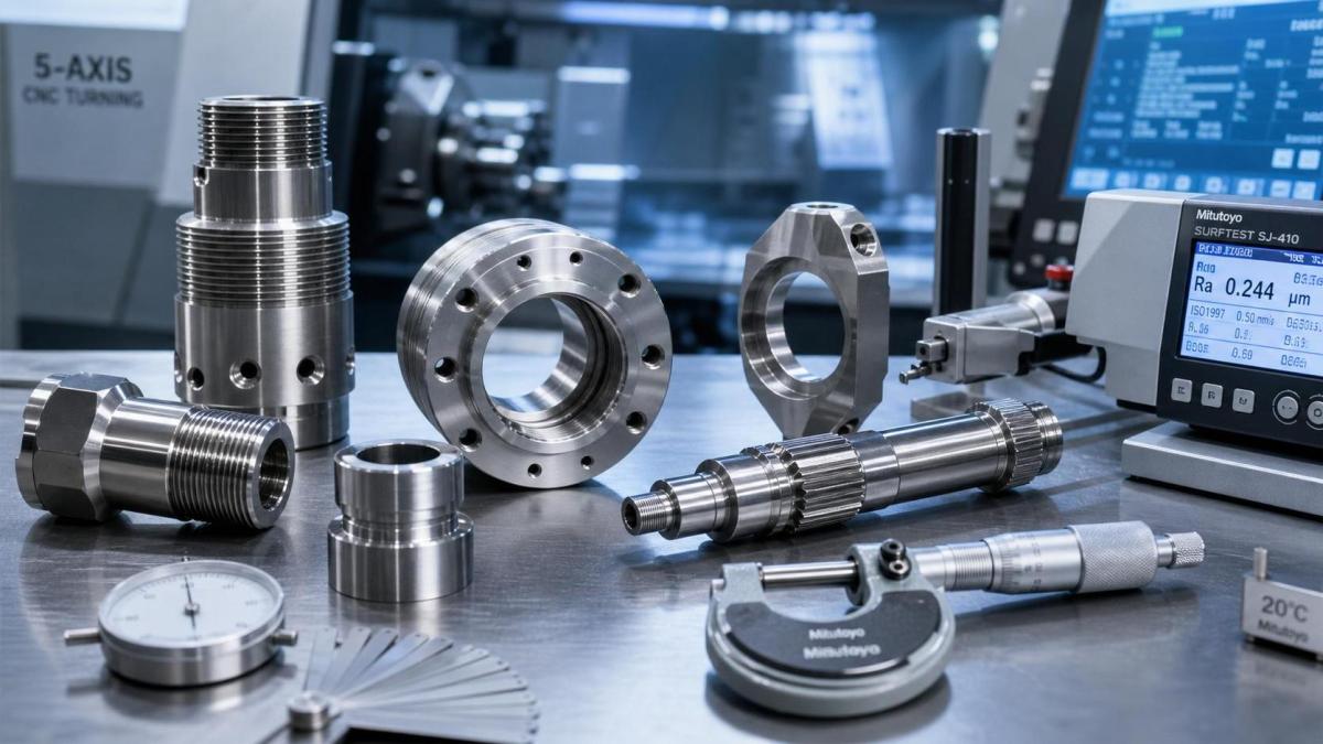
Aerospace cnc turning parts are usually rotationally symmetric, but the manufacturing risk is rarely simple. Shafts, bushings, spacers, threaded fittings, valve bodies, collars, and bearing seats often combine tight diameters, concentric features, fine threads, and critical sealing surfaces in one part.
The issue is not only dimensional accuracy. These parts must also survive vibration, thermal cycling, pressure loading, corrosion exposure, and long service intervals. A dimension can pass inspection while the part still fails in use because material condition, residual stress, burr formation, or surface damage was not controlled.
This is also where TSV’s data-first viewpoint matters. In precision machining, noise enters when suppliers describe capability in generic terms. The useful questions are narrower: What CpK is maintained on bearing diameters? Which lot certifications support the alloy? How is surface roughness verified after coating or passivation? Those details decide whether a supplier is truly aerospace-ready.
Tolerance bands are functional requirements, not cosmetic targets
For aerospace cnc turning parts, tolerance selection starts with function. A static spacer does not need the same control level as a bearing journal, a sealing land, or a threaded pressure fitting. Yet many sourcing errors begin when tolerance values are copied from legacy drawings without checking actual service demands.
Typical turned aerospace features often fall into these practical ranges:
These values are not universal specifications. They are realistic working ranges seen across many aerospace machining programs. The correct requirement always depends on mating conditions, load path, temperature, and certification context.
More important than a tight number on paper is process stability. A supplier that can occasionally hit ±0.003 mm is less valuable than one that holds it predictably across batches, machines, and operators. For safety review, capability data, first article inspection, and gauge strategy are often more revealing than a sample part that looks perfect.
Where tolerance risk usually hides
- Datum schemes that ignore how the part is actually clamped or assembled.
- Stacked limits across threads, grooves, shoulders, and mating bores.
- Thermal drift during long turning cycles on slender parts.
- Post-process changes after coating, heat treatment, or shot peening.
- Inspection reports that list pass or fail without uncertainty data.
Material choice changes the machining window and the service life
When aerospace cnc turning parts are reviewed only by geometry, a large part of the risk remains invisible. Material selection controls strength-to-weight ratio, corrosion resistance, thermal expansion, machinability, galling behavior, and fatigue response. It also affects tool wear, burr formation, and surface integrity during turning.
Several alloys appear repeatedly in aerospace turned components:
Approval is never just the alloy name. Aerospace programs typically require mill test reports, heat numbers, process route records, and confirmation of temper or heat-treatment condition. Substituting 17-4 PH H900 for H1025, for example, can alter strength and toughness enough to change service suitability.
From a broader industrial view, this is one reason multi-sector supply chains struggle. Parts may look identical across aviation, defense, robotics, and high-end automation, yet the material pedigree expectation is not equal. TSV’s position is useful here: strip away generic comparability and benchmark the actual parameter set for the intended environment.
Surface finish affects sealing, fatigue, friction, and inspection confidence
For aerospace cnc turning parts, surface finish is not an afterthought added to the drawing margin. Roughness changes contact stress, crack initiation behavior, lubricant retention, sealing efficiency, and coating adhesion. In critical assemblies, the finish may be as functional as the dimension itself.
A practical way to interpret common finish expectations is shown below:
Roughness numbers alone can still mislead. Lay direction, torn grain, chatter marks, embedded particles, and edge break condition may not appear in a simple Ra value. A part can meet finish numerically while remaining unacceptable for fatigue or sealing service.
This is especially relevant after secondary processing. Anodizing, passivation, plating, grinding, polishing, or shot peening may improve one property while shifting another. Inspection plans should confirm the required final state, not only the pre-treatment surface.
What should be checked beyond the drawing
A drawing defines intent, but aerospace cnc turning parts are approved through a larger control package. In practice, several review points often separate reliable suppliers from risky ones.
Process and traceability signals
- AS9100-aligned quality management and documented process flow.
- Material traceability from incoming bar stock to finished lot.
- First Article Inspection records, often aligned with AS9102 practice.
- Calibration status for micrometers, bore gauges, profilometers, and CMM systems.
- Defined control of deburring, cleaning, packaging, and foreign object prevention.
Common failure triggers during supplier review
- Capability claimed without lot-by-lot measurement evidence.
- Material certificates that stop at distributor level.
- Surface finish checks taken on non-functional areas only.
- Thread inspection performed without proper gauge control.
- No clear plan for managing rework on critical dimensions.
In mixed industrial ecosystems, where aerospace suppliers may also serve robotics, sensors, or UAV platforms, these controls become even more important. Shared equipment does not automatically mean shared qualification level. The review should stay anchored in measurable compliance and part-specific risk.
How to use this information in real sourcing and quality decisions
The most useful next step is to translate broad part demand into a parameter-led checklist. For aerospace cnc turning parts, that means ranking every critical feature by function, then linking each feature to a verification method, material proof, and final surface requirement.
A practical review path usually includes three questions. Which dimensions are safety-critical? Which material conditions are non-substitutable? Which surfaces influence sealing, wear, or fatigue life? Once those are clear, supplier comparison becomes more objective and less vulnerable to sales language.
That approach also aligns with TSV’s broader mission in hard-tech benchmarking. Parameters do not remove every uncertainty, but they sharply reduce avoidable ambiguity. In aerospace machining, that reduction matters because inspection escape, undocumented substitution, or finish-related failure often costs far more than the part itself.
Before releasing a new RFQ or approving a new source, it is worth revisiting the specification package with fresh discipline: define the real tolerance need, validate the approved material route, require final-state surface data, and confirm traceability from raw stock to shipment. That is usually where stronger decisions begin.
Search News
Hot Articles
- Carbon Fiber StructuresHow to Specify Aerospace Carbon Fiber Assemblies for Lightweight, Load-Bearing PartsJul 11, 2026
- Machine VisionXiaomi, Alibaba DAMO Academy Drive Open-Source Robotics Model Ecosystem, Lowering Algorithm Development Barriers for Overseas SMEs Adopting Chinese Robotics SolutionsMar 30, 2026
- Cobots & ArmsShanxi 'AI+' Conference Showcases Embodied Intelligence with Multinational Buyer Engagement: Key Industry ImplicationsMar 30, 2026
Popular Tags
Recommended News
 Jul 11, 2026How to Specify Aerospace Carbon Fiber Assemblies for Lightweight, Load-Bearing PartsAerospace carbon fiber assemblies: learn how to specify laminate design, load data, joining methods, and inspection controls for lighter, reliable load-bearing aerospace parts.Elena Rostova (UAV Systems Researcher)
 Mar 30, 2026Xiaomi, Alibaba DAMO Academy Drive Open-Source Robotics Model Ecosystem, Lowering Algorithm Development Barriers for Overseas SMEs Adopting Chinese Robotics SolutionsXiaomi & Alibaba DAMO Academy's open-source robotics models lower algorithm barriers for global SMEs. Boost efficiency in manufacturing, logistics & smart retail with ROS 2 compatible solutions.TSV Data Lab
 Mar 30, 2026Shanxi 'AI+' Conference Showcases Embodied Intelligence with Multinational Buyer Engagement: Key Industry ImplicationsShanxi 'AI+' Conference highlights embodied intelligence with Tesla, Ubtech & Jiantao showcasing multimodal robotics. 40+ global buyers validated tech on-site, creating new B2B channels for industrial automation & AI solutions.Chen Wei (Automation Lead Engineer)
 Mar 30, 2026Zhongguancun Unveils 6G Integrated Sensing-Computing-Intelligence Platform to Empower Embodied Robots for Global Industrial ApplicationsZhongguancun's new 6G platform revolutionizes industrial robotics with <10ms latency, empowering global automotive, logistics & port automation. Discover how this tech boosts China's smart manufacturing exports.TSV Data Lab
 Mar 30, 2026Mech-Mind Tianjin Embodied Intelligence R&D and Production Base Goes Live, Cutting Delivery Time by 20%–30% for Global Customized AMR+Vision SolutionsMech-Mind's Tianjin AMR+Vision production base cuts delivery time by 20%-30% for欧美 & Latin American markets. Discover how this PLd-certified facility accelerates customized robotics solutions for smart manufacturing and logistics.Chen Wei (Automation Lead Engineer)
 Mar 30, 2026Boao Forum Reveals 'Co-evolution of Big and Small Brains' Trend in Humanoid Robots, China's Embodied Intelligence Accelerates Adaptation to Overseas Manufacturing Service ScenariosDiscover how China's humanoid robots, featuring 'Co-evolution of Big and Small Brains,' are revolutionizing global manufacturing. Learn about Embodied Tian Gong 3.0's ISO compliance and overseas deployment at Boao Forum 2026.Chen Wei (Automation Lead Engineer)
 Mar 30, 2026China Railway Industrial Secures Patent for Embodied Robotics in Material Handling, Boosting High-Precision Delivery Capabilities for Overseas Infrastructure and Manufacturing ProjectsChina Railway Industrial's new patent for embodied robotics in material handling boosts high-precision delivery for global infrastructure & manufacturing. Discover how this innovation enhances logistics accuracy in automotive, rail transit & EPC projects.Chen Wei (Automation Lead Engineer)
 Sep 27, 2026How to Select Wall-Mount Edge Devices for Space-Constrained Factory NetworksWall mount edge devices for space-constrained factories: evaluate workload, thermal design, power resilience, cable access, and network reliability for smarter deployments.TSV Data Lab
 Sep 26, 2026Machining Tolerance Analysis: How to Set Limits That Meet Function and Cost TargetsMachining tolerance analysis: learn how to set functional limits, control tolerance stacks, reduce inspection risk, and balance precision with production cost.Dr. Marcus Vance
 Sep 25, 2026How to Evaluate an Industrial Infrastructure Data Platform for Multi-Site OperationsIndustrial infrastructure data platform evaluation guide for multi-site operations: compare data quality, edge resilience, interoperability, governance, and scalable proof-of-value criteria.Victor Lin (Chief Software Architect)
 Sep 24, 2026How to Select Machine Vision Optics for Accurate Inspection at Different Working DistancesMachine vision optics selection guide for accurate inspection at every working distance. Compare FOV, pixel scale, DOF, distortion, lighting, and telecentric options.TSV Data Lab
 Sep 23, 2026How to Evaluate a Machine Vision System Integrator for High-Speed Inspection LinesChoose a machine vision system integrator with proven expertise in high-speed inspection, reliable reject timing, robust optics, and measurable acceptance criteria.TSV Data Lab
 Sep 27, 2026How SCADA data integration improves traceability across production linesSCADA data integration connects production-line data to improve traceability, accelerate quality investigations, and strengthen safety decisions.Victor Lin (Chief Software Architect)
 Sep 26, 2026What to define before starting SCADA integration planningSCADA integration planning starts with clear scope, control boundaries, data models, cybersecurity, and testing. Discover the definitions that reduce risk and costly rework.Victor Lin (Chief Software Architect)
 Sep 25, 2026How a smart factory with Industrial IoT reduces production blind spotsDiscover how a smart factory with Industrial IoT turns real-time machine, quality, and workflow data into actionable insights that reduce production blind spots and delivery risks.Victor Lin (Chief Software Architect)
 Sep 24, 2026When does Industrial IoT make smart manufacturing easier to scale?Smart manufacturing Industrial IoT scales when trusted data, interoperable systems, and secure workflows turn connected assets into measurable gains.TSV Data Lab
 Sep 23, 2026What drives ultra-precision machining cost at 1-micron tolerance?Ultra precision machining cost per part at 1 micron tolerance depends on process, material, metrology, and yield. Learn how to compare quotes confidently.Dr. Marcus Vance
 Sep 22, 2026Drone Engine-T550CC Applications: Build the UAV Power System Around the MissionAn application guide for Drone Engine-T550CC integration, covering payload planning, airframe matching, cooling, fuel, vibration, test procedures, documentation, and service preparation.Elena Rostova (UAV Systems Researcher)
 Sep 22, 2026How to Evaluate Industrial Edge Computing Vendors for Factory DeploymentIndustrial edge computing vendor evaluation guide for factories: compare latency, protocol fit, reliability, security, and lifecycle support before deployment.TSV Data Lab
 Sep 21, 2026Drone Payload Integration: Matching Power, Data, and Center of Gravity for Reliable FlightsDrone payload integration made practical: balance power, data, center of gravity, and endurance to build safer, more reliable mission-ready flights.Elena Rostova (UAV Systems Researcher)
 Sep 20, 2026Autonomous Navigation Pricing: Cost Drivers and Budget Benchmarks for AMR ProjectsAutonomous navigation price explained: compare AMR cost drivers, software, sensors, integration, safety, and lifecycle budgets to build a scalable project plan.Chen Wei (Automation Lead Engineer)
 Sep 19, 2026How to Scope Automation Integration Services for Multi-System Factory ProjectsAutomation integration services: learn how to scope multi-system factory projects with clear workflows, interface contracts, safety boundaries, and acceptance criteria.Victor Lin (Chief Software Architect)
 Sep 18, 2026Selecting UAV Aerospace Structural Parts for Strength, Weight, and Fatigue LifeUAV aerospace structural parts guide: compare strength, weight, stiffness, fatigue life, joints, and traceability to select reliable flight-ready components.Elena Rostova (UAV Systems Researcher)
 Sep 17, 2026Selecting Commercial Drone Payloads for European Inspection ProjectsCommercial drone payloads Europe: learn how to select RGB, thermal and LiDAR systems for compliant, reliable inspection data and better project outcomes.Elena Rostova (UAV Systems Researcher)