AS9100 CNC Machining Tolerances Chart: What Shops Often Misread
Publication Date
author
An AS9100 CNC machining tolerances chart should clarify risk, yet many shops still misread limits, inspection intent, and aerospace-critical acceptance criteria. For quality and safety leaders, that gap can trigger nonconformance, audit findings, and supplier uncertainty. This article explains where interpretation often fails and how to read tolerance data with the precision AS9100 environments demand.
Why scenario differences matter more than the chart itself
In aerospace and adjacent high-reliability manufacturing, an AS9100 CNC machining tolerances chart is rarely a standalone decision tool. Quality teams, safety managers, and supplier auditors use it inside a wider control system that includes drawing interpretation, process validation, first article inspection, revision control, and risk-based acceptance. The same dimensional value can have a very different consequence depending on whether the part is a prototype bracket, a flight-adjacent housing, or a safety-critical load path component.
This is where many shops go wrong. They treat the chart as a shop-floor convenience table instead of a contract-linked quality requirement. A tolerance note that seems generous in a general machining context may be extremely narrow once geometric relationships, datum schemes, surface integrity, and downstream assembly stack-up are considered. For quality control personnel, the practical question is not “What does the number say?” but “In which production scenario does this number apply, and what evidence supports compliance?”
TechStat Vanguard consistently sees that the biggest failures happen at the interpretation boundary: between engineering intent and machine capability, between a nominal tolerance and a process window, and between accepted inspection habits and AS9100 documentation expectations. That is why reading an AS9100 CNC machining tolerances chart should always be scenario-based.
Typical contexts where misreading begins
- Supplier qualification for aerospace or UAV programs
- FAI preparation under AS9102-linked workflows
- Drawing review before RFQ or contract acceptance
- Incoming inspection disputes between customer and machine shop
- NCR/CAPA investigations after dimensional drift or assembly failure
A fast scenario comparison for quality leaders
Scenario 1: RFQ, contract review, and supplier onboarding
The first high-risk scenario appears before any chips are cut. During RFQ and contract review, buyers often ask whether a supplier can meet an AS9100 CNC machining tolerances chart. Shops may answer based on generic machine capability, but quality leaders should push deeper. A tolerance chart does not prove the shop understands drawing notes, key characteristics, special process dependencies, or the required inspection evidence tied to aerospace acceptance.
For procurement and supplier quality teams, the practical issue is fit-for-scenario. A shop that can machine ±0.01 mm on a stable aluminum block may still struggle with thin-wall titanium, post-heat-treatment distortion, or bore-to-datum positional control after secondary operations. In onboarding, the chart should be treated as a screening input, not as final proof of conformity.
This is also the stage where “standard tolerance” language is frequently misused. Some suppliers present a default tolerance table as if it overrides the drawing. Under AS9100-controlled work, it does not. The contract, revision-controlled drawing, customer flow-downs, and approved deviations always govern.
What quality and safety teams should verify at onboarding
The best onboarding reviews are scenario-specific. If the part is flight-adjacent but not structurally critical, the emphasis may be on dimensional repeatability and traceable inspection. If the part enters a fuel, actuator, or thermal management system, then process discipline, cleanliness controls, and feature-level verification become more important than a marketing claim about “tight tolerances.”
Minimum questions to ask before approval
- Which tolerances come from the drawing, and which are merely shop defaults?
- How are datum features established, inspected, and recorded?
- What process controls exist for material movement, heat, and distortion?
- Is capability demonstrated on similar geometry, material, and lot size?
- What evidence supports first article, in-process, and final inspection?
If these questions are not answered clearly, the AS9100 CNC machining tolerances chart is being used as a sales artifact rather than a quality control tool.
Scenario 2: First article inspection and launch-to-production transition
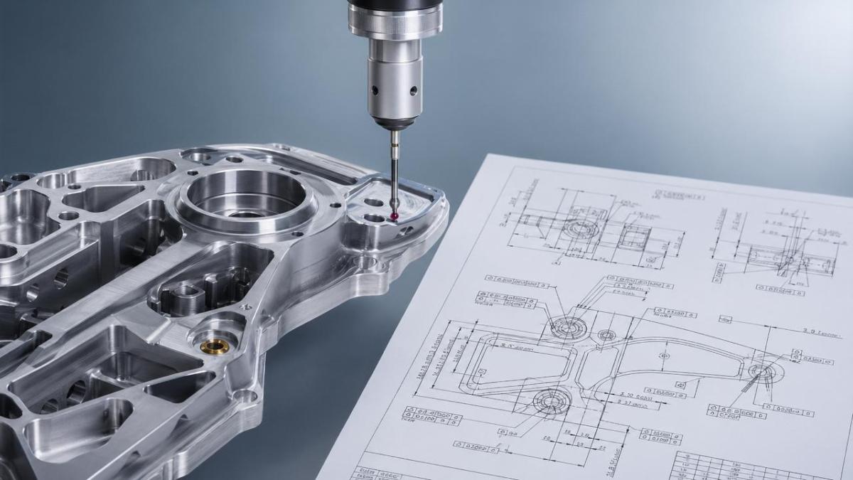
A second major misread happens during first article inspection. Teams often assume that if measured dimensions fall within the chart range on the first run, the process is production-ready. That assumption is dangerous. FAI confirms conformance to engineering requirements at a defined moment; it does not automatically prove long-term process capability across shifts, tools, operators, material lots, and environmental variation.
For AS9100 environments, launch control must distinguish between part acceptance and process confidence. A part can pass once while the process remains unstable. This is especially true for complex 5-axis parts, thin sections, composite-compatible metallic interfaces, and features sensitive to clamping sequence or thermal growth. A narrow reading of the AS9100 CNC machining tolerances chart misses these scenario realities.
Quality managers should therefore use FAI as an interpretation checkpoint. If a nominally simple flatness or position callout required unusual operator compensation, manual polishing, selective holding strategy, or repeated offsets, then the chart alone is not describing the true production risk.
Where launch teams often misjudge tolerance evidence
- Confusing one successful setup with repeatable serial control
- Ignoring inspection uncertainty relative to the tolerance band
- Treating reworked features as equivalent to first-pass capability
- Failing to connect dimensional results with downstream assembly performance
How to read the chart in launch scenarios
In a launch setting, the chart should be interpreted alongside process behavior. Ask whether the tolerance was achieved through normal controls, whether the measurement method is suitable for the feature, and whether the reported values leave enough process margin. A process running near the edge of the allowed band may satisfy the print but still create elevated risk for escapes and audit findings.
For quality and safety stakeholders, the useful decision is not binary approval alone. It is whether to approve, approve with containment, require capability improvement, or hold launch until metrology and control plans match the true aerospace risk.
Scenario 3: Safety-critical, fatigue-sensitive, or assembly-critical parts
The most serious consequences occur when a shop reads an AS9100 CNC machining tolerances chart as if all features carry equal importance. In reality, some dimensions influence fit, others influence function, and some influence safety margin. On fatigue-sensitive or assembly-critical parts, dimensional acceptance cannot be separated from geometry relationships, surface finish, edge condition, and process-induced damage.
This matters in brackets, housings, linkage components, actuator interfaces, UAV structural nodes, and high-vibration mounting features. A diameter may be in tolerance, yet the coaxiality, perpendicularity, or surface integrity may still create failure risk. Shops that rely only on linear dimensions from a tolerance chart often miss how AS9100-controlled environments expect verification of the full design intent.
Safety managers should be especially alert when the supplier says a feature is “within normal shop tolerance” but cannot show how datum reference frames, GD&T requirements, or critical characteristic controls were applied. That language often signals a generic machining mindset rather than an aerospace compliance mindset.
Critical features that are often under-read
A practical rule for high-risk parts
If the feature affects load transfer, sealing, dynamic alignment, fatigue life, or controlled movement, do not rely on the tolerance chart as the main acceptance lens. Read it only as one layer inside the part’s risk architecture.
Scenario 4: Incoming inspection, nonconformance review, and supplier disputes
Another common application scenario is conflict resolution. The supplier says the part passed; incoming inspection says it failed. In these cases, the AS9100 CNC machining tolerances chart is often cited by both sides, but the real gap usually lies elsewhere: measurement method, setup replication, datum selection, environmental condition, feature interpretation, or drawing revision mismatch.
Quality teams should be cautious about accepting chart-based arguments without metrology context. Two competent inspectors can obtain different results if one measures in free state and the other in restrained state, or if one evaluates a geometric feature through sampled points while the other uses a more complete scan strategy. Under AS9100 expectations, acceptance should be based on controlled and documented methods, not informal shop habits.
This scenario is especially important for supplier development. Repeated disputes signal that the issue may not be machine accuracy, but interpretation discipline. That distinction matters because the corrective action for a capability problem is different from the corrective action for a documentation or metrology problem.
A structured dispute review path
- Confirm drawing revision, customer notes, and approved deviations.
- Verify whether the disputed feature is dimensional, geometric, or condition-based.
- Compare fixture logic, datum establishment, and measurement equipment.
- Assess measurement uncertainty against the tolerance band.
- Decide whether the root cause is process, inspection, or requirement ambiguity.
For safety leaders, this method is valuable because it reduces emotional debate and pushes the review back to objective engineering evidence, which is exactly the discipline AS9100 systems are meant to reinforce.
How different organizations should use an AS9100 CNC machining tolerances chart
Not every organization should use the chart in the same way. A contract manufacturer may use it as part of process planning. A supplier quality engineer may use it to test whether a source truly understands aerospace controls. A safety manager may focus on whether tolerance interpretation is strong enough to prevent latent risk from reaching assembly or service. The key is role-based use, not generic reference.
For smaller shops entering aerospace, the biggest need is often translation: turning machine capability claims into documented compliance logic. For mature aerospace suppliers, the issue is usually standardization across cells, shifts, sites, and subcontractors. In both cases, the AS9100 CNC machining tolerances chart becomes useful only when paired with explicit process ownership.
The best-performing organizations do not ask only whether the tolerance is possible. They ask whether it is controllable, inspectable, repeatable, and defensible under audit.
Role-based application guide
- Quality control personnel: compare chart values to inspection method suitability and acceptance records.
- Safety managers: identify which tolerances connect directly to failure modes or assembly hazards.
- Supplier quality engineers: verify that shop claims align with real evidence on similar parts and materials.
- Procurement leaders: avoid awarding work solely on stated tolerance capability without process proof.
Common misreads to eliminate and the next action to take
Across all scenarios, the same pattern appears: the chart is over-trusted, while the surrounding quality system is under-checked. The result is preventable confusion during qualification, launch, inspection, and corrective action. For organizations working in aerospace, UAV, advanced automation, or other hard-tech sectors, this is more than a documentation problem. It is a risk transfer problem.
If you want better outcomes, treat every AS9100 CNC machining tolerances chart as a trigger for deeper questions. Which features are function-critical? Which are process-sensitive? Which need enhanced verification? Which require customer clarification before production starts? This approach reduces supplier ambiguity and strengthens audit readiness at the same time.
For quality and safety teams, the next action is straightforward: map your current tolerance review process against your real operating scenarios. Separate prototype logic from serial production logic, isolate safety-critical features from general dimensions, and standardize how measurement evidence is linked to drawing intent. When that discipline is in place, the chart stops being a source of misreading and becomes what it should be: a precise reference inside a robust AS9100 control framework.
Final checklist for immediate use
- Never let a shop default tolerance override the drawing or contract flow-down.
- Review tolerances by scenario: onboarding, FAI, serial production, and NCR review.
- Escalate any feature tied to fit, load, motion, sealing, or fatigue.
- Validate metrology method before accepting any dispute resolution claim.
- Use the AS9100 CNC machining tolerances chart together with capability, traceability, and risk controls.
Search News
Hot Articles
- Carbon Fiber StructuresHow to Specify Aerospace Carbon Fiber Assemblies for Lightweight, Load-Bearing PartsJul 11, 2026
- Machine VisionXiaomi, Alibaba DAMO Academy Drive Open-Source Robotics Model Ecosystem, Lowering Algorithm Development Barriers for Overseas SMEs Adopting Chinese Robotics SolutionsMar 30, 2026
- Cobots & ArmsShanxi 'AI+' Conference Showcases Embodied Intelligence with Multinational Buyer Engagement: Key Industry ImplicationsMar 30, 2026
Popular Tags
Recommended News
 Jul 11, 2026How to Specify Aerospace Carbon Fiber Assemblies for Lightweight, Load-Bearing PartsAerospace carbon fiber assemblies: learn how to specify laminate design, load data, joining methods, and inspection controls for lighter, reliable load-bearing aerospace parts.Elena Rostova (UAV Systems Researcher)
 Mar 30, 2026Xiaomi, Alibaba DAMO Academy Drive Open-Source Robotics Model Ecosystem, Lowering Algorithm Development Barriers for Overseas SMEs Adopting Chinese Robotics SolutionsXiaomi & Alibaba DAMO Academy's open-source robotics models lower algorithm barriers for global SMEs. Boost efficiency in manufacturing, logistics & smart retail with ROS 2 compatible solutions.TSV Data Lab
 Mar 30, 2026Shanxi 'AI+' Conference Showcases Embodied Intelligence with Multinational Buyer Engagement: Key Industry ImplicationsShanxi 'AI+' Conference highlights embodied intelligence with Tesla, Ubtech & Jiantao showcasing multimodal robotics. 40+ global buyers validated tech on-site, creating new B2B channels for industrial automation & AI solutions.Chen Wei (Automation Lead Engineer)
 Mar 30, 2026Zhongguancun Unveils 6G Integrated Sensing-Computing-Intelligence Platform to Empower Embodied Robots for Global Industrial ApplicationsZhongguancun's new 6G platform revolutionizes industrial robotics with <10ms latency, empowering global automotive, logistics & port automation. Discover how this tech boosts China's smart manufacturing exports.TSV Data Lab
 Mar 30, 2026Mech-Mind Tianjin Embodied Intelligence R&D and Production Base Goes Live, Cutting Delivery Time by 20%–30% for Global Customized AMR+Vision SolutionsMech-Mind's Tianjin AMR+Vision production base cuts delivery time by 20%-30% for欧美 & Latin American markets. Discover how this PLd-certified facility accelerates customized robotics solutions for smart manufacturing and logistics.Chen Wei (Automation Lead Engineer)
 Mar 30, 2026Boao Forum Reveals 'Co-evolution of Big and Small Brains' Trend in Humanoid Robots, China's Embodied Intelligence Accelerates Adaptation to Overseas Manufacturing Service ScenariosDiscover how China's humanoid robots, featuring 'Co-evolution of Big and Small Brains,' are revolutionizing global manufacturing. Learn about Embodied Tian Gong 3.0's ISO compliance and overseas deployment at Boao Forum 2026.Chen Wei (Automation Lead Engineer)
 Mar 30, 2026China Railway Industrial Secures Patent for Embodied Robotics in Material Handling, Boosting High-Precision Delivery Capabilities for Overseas Infrastructure and Manufacturing ProjectsChina Railway Industrial's new patent for embodied robotics in material handling boosts high-precision delivery for global infrastructure & manufacturing. Discover how this innovation enhances logistics accuracy in automotive, rail transit & EPC projects.Chen Wei (Automation Lead Engineer)
 Oct 28, 2026IDC: Global Quadruped Robot Shipments Rise 92.5% in H1 2026 as Volume and Value DivergeGlobal quadruped robot shipments rose 92.5% in H1 2026, according to IDC. Explore what diverging volume and value trends mean for industrial buyers and manufacturers.Chen Wei (Automation Lead Engineer)
 Oct 28, 2026Interpreting Industrial IoT Latency Data for Monitoring and Real-Time ControlInterpret industrial category latency data to assess jitter, deadline misses, and real-time readiness. Learn how to benchmark IIoT systems and choose monitoring and control solutions.TSV Data Lab
 Oct 27, 2026GXO and Agility Robotics Expand Partnership to Accelerate US Humanoid Robot DeploymentGXO and Agility Robotics plan to expand US humanoid robot deployment with Digit 4 in early 2027. Explore warehouse automation plans, service terms and future Digit 5 upgrades.Chen Wei (Automation Lead Engineer)
 Oct 27, 2026Robotic Automation Costs: Budgeting for Equipment, Integration, and MaintenancePlan your robotics automation cost with confidence. Explore equipment, integration, and maintenance expenses, compare quotes, and build a realistic budget for better ROI.Chen Wei (Automation Lead Engineer)
 Oct 26, 2026AMAXiMAL Releases Open-Source TopMod 3D v3 With Claude AIExplore AMAXiMAL’s free, open-source TopMod 3D v3 with Claude AI assistance, topology-based modeling and plywood fabrication tools that connect complex designs to physical builds.Dr. Marcus Vance
 Oct 26, 2026Choosing a SCADA System Integrator Company: PLC Compatibility and Long-Term SupportChoose a scada system integrator company with proven PLC compatibility and reliable long-term support. Discover what to test, compare, and require before investing.Victor Lin (Chief Software Architect)
 Oct 25, 2026Hesai Leads Global ADAS Main Lidar Shipments in Yole’s 2026 ReportHesai led global ADAS main lidar shipments with a 43% share in 2025, according to Yole’s 2026 report. Explore what this ranking reveals about its automotive market position.TSV Data Lab
 Oct 25, 2026Choosing an Aerospace Materials Manufacturer: Quality and Traceability ChecksChoosing an aerospace materials manufacturer? Learn how to verify certifications, test reports, and lot traceability to qualify suppliers confidently and reduce costly sourcing risks.Dr. Marcus Vance
 Oct 24, 2026Guotai Haitong: Global Entry-Level 3D Printer Shipments Rose 39% in Q1 2026Entry-level 3D printer shipments rose 39% in Q1 2026, Guotai Haitong reports. Explore how AI, multicolor printing and print farms are shaping market growth.Dr. Marcus Vance
 Oct 24, 2026Choosing an Industrial Vision Inspection Supplier: Acceptance Tests That MatterChoose an industrial vision inspection supplier with confidence. Discover acceptance tests for defect detection, false rejects, production speed, and reliable part rejection before you buy.TSV Data Lab
 Oct 23, 2026US Navy Raises Gecko Robotics Contract Ceiling to $300M for Robotic Fleet MaintenanceUS Navy raises Gecko Robotics’ contract ceiling to $300M for Pacific Fleet robotic inspections. Explore potential opportunities for maintenance suppliers and key procurement considerations.Chen Wei (Automation Lead Engineer)
 Oct 23, 2026Choosing Industrial Sensing Systems for Global Plants: Protocol CompatibilityCompare industrial sensing systems international buyers can trust. Explore protocol compatibility, reduce integration risks, and select proven configurations for reliable global plant deployments.TSV Data Lab
 Oct 22, 2026KUKA Showcases Physical AI and iiQKA.AI Vision at NVIDIA GTC BerlinExplore KUKA’s Physical AI showcase at NVIDIA GTC Berlin and discover how iiQKA.AI Vision aims to simplify robotic vision integration and improve 2D and 3D scene recognition.TSV Data Lab
 Oct 22, 2026Robotic Machining of Advanced Composites: What Tolerances Are Achievable?Explore advanced materials machining robotics: discover what drives achievable composite tolerances and how to validate accuracy before investing in your next machining system.Dr. Marcus Vance
 Oct 21, 2026China’s Industrial Robot Exports Near RMB 10 Billion in First Nine Months of 2026China’s industrial robot exports neared RMB 10 billion in January–September 2026, with value rising faster than volume. Explore the data and what it could mean for suppliers.Chen Wei (Automation Lead Engineer)
 Oct 21, 2026Low-Latency Industrial Data Processing: Pricing and Key Cost DriversExplore industrial data latency price drivers, from edge hardware to integration and support. Learn how to compare quotes, verify performance, and avoid unnecessary costs.TSV Data Lab
 Oct 20, 2026KUKA Launches iiQKA.AI Vision to Simplify Industrial Image ProcessingKUKA iiQKA.AI Vision simplifies industrial image processing with controller-based 2D and 3D vision. Explore drag-and-drop setup for vision-guided automation.TSV Data Lab