
Aerospace parts reverse engineering where accuracy is usually lost
Publication Date
author
In aerospace parts reverse engineering, accuracy is usually lost not in scanning alone, but across data capture, material interpretation, and manufacturing transfer. For engineers, buyers, and decision-makers comparing an aerospace carbon fiber molding process, solid state LiDAR manufacturer China options, or an industrial 3D vision camera supplier, understanding where tolerances drift is essential to reducing risk, shortening validation cycles, and turning engineering data into reliable production outcomes.
Where aerospace reverse engineering usually loses accuracy
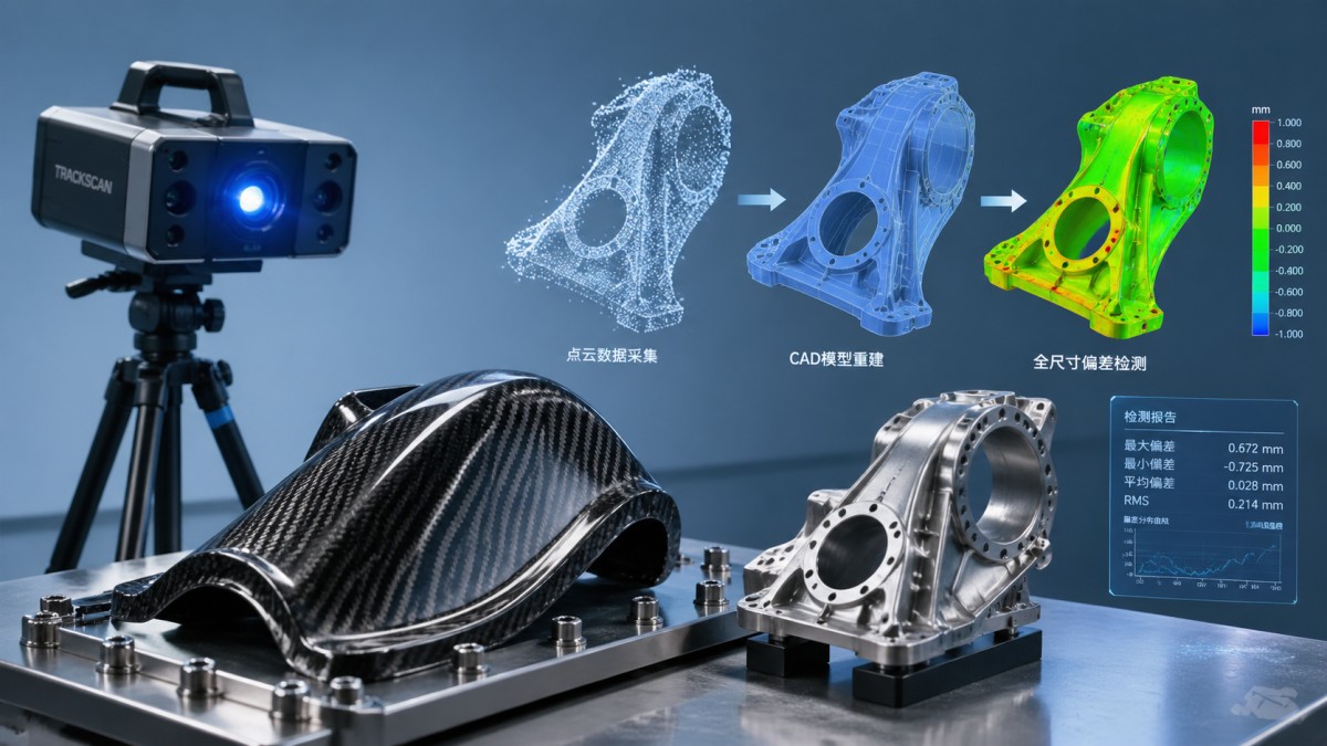
The short answer is this: most aerospace parts reverse engineering errors happen at the interfaces between steps, not inside one isolated tool. A scan may look precise, yet the final part still fails fit, fatigue, or certification expectations because geometry, datum strategy, material behavior, and process capability were not carried through as one controlled system.
For most target readers, the key concern is not whether reverse engineering is possible. It is whether the reproduced part will be dimensionally stable, manufacturable, inspectable, and defensible in a high-risk supply chain. That is especially true for procurement teams qualifying new suppliers, engineers rebuilding legacy parts, and executives trying to reduce downtime without creating hidden compliance or performance risk.
In practice, accuracy is usually lost in six places:
- Initial data capture: poor line-of-sight, reflective surfaces, inadequate point density, or unstable fixturing.
- Datum and alignment definition: scans are converted into models without preserving functional reference frames.
- Surface reconstruction: point cloud smoothing, mesh repair, and CAD rebuilding introduce unintended geometric changes.
- Material and process interpretation: the part shape is copied, but springback, layup logic, heat treatment response, or machining distortion are not.
- Tolerance transfer: nominal geometry is recreated, but critical fit and interface tolerances are guessed rather than derived from function.
- Manufacturing execution: the chosen CNC, composite, additive, or inspection workflow cannot hold what the model assumes.
This is why aerospace reverse engineering should never be treated as “scan-to-CAD” only. It is a full engineering translation problem.
Why scanning alone does not guarantee a usable aerospace part
Many organizations overestimate what 3D scanning can solve. High-resolution optical systems, CT, structured light, and even advanced sensor stacks can capture dense geometry data, but they do not automatically identify design intent. In aerospace, design intent matters as much as nominal shape.
A bracket, duct, housing, fairing, or composite mold may contain surfaces that look simple but are functionally linked to load paths, mating interfaces, seal compression, airflow behavior, or installation sequences. If the reverse engineering team recreates what the part looks like without understanding what the part must do, dimensional fidelity can still produce a functionally wrong result.
For example:
- A scanned mounting part may reproduce edge geometry well, yet lose the true hole pattern relationship to its installation datum.
- A composite shell may match external form but fail after cure because the original aerospace carbon fiber molding process included fiber orientation and tool compensation not visible in the scan.
- A turbine-adjacent component may appear dimensionally valid but distort in production because thermal behavior of the replacement alloy was not modeled.
For operating teams and buyers, this means one practical thing: when evaluating an industrial 3D vision camera supplier, solid state LiDAR manufacturer China source, or metrology vendor, the hardware specification alone is not enough. You must ask how their data supports downstream reconstruction, tolerance analysis, and production repeatability.
The biggest accuracy loss points from capture to CAD reconstruction
If your goal is to reduce risk, these are the most important technical checkpoints to review before approving any aerospace parts reverse engineering workflow.
1. Part condition before capture
Legacy aerospace parts are often worn, repaired, thermally cycled, or plastically deformed. If the scanned sample is not representative of true design condition, the entire reverse engineering project starts with bias. Teams should first determine whether they are reproducing an as-designed, as-built, or as-worn state.
2. Fixturing and reference strategy
Improper support can deform thin-wall metal or composite parts during scanning. Just as important, if the part is not referenced to functional datums early, later CAD reconstruction may drift away from the interfaces that actually matter in service.
3. Sensor selection versus feature type
No sensor is universally best. Structured light may be effective for high-detail external features. CT can reveal internal geometry. Laser scanning may support larger surfaces. Machine vision and solid-state sensing can assist automated inspection cells, but each method has tradeoffs in reflectivity, resolution, speed, and uncertainty. The wrong sensing approach often creates false confidence rather than obvious failure.
4. Point cloud cleanup and smoothing
Noise reduction is necessary, but aggressive smoothing can erase edges, blend transitions, and change radii. This is a common hidden source of lost accuracy because the processed data looks cleaner while becoming less true.
5. Mesh-to-CAD interpretation
Converting scan data into parametric surfaces often requires human judgment. If the engineer imposes “ideal” geometry where the original part used controlled asymmetry, local compensation, or manufacturing-driven shape variation, the rebuilt model may become elegant but wrong.
6. Tolerance assumption without functional analysis
Many projects fail here. Reverse engineering teams rebuild the nominal form but cannot confidently define which dimensions are critical, which are adjustable, and which are non-functional. In aerospace, guessing tolerances is a major validation and procurement risk.
Why material behavior and process replication matter as much as geometry
This is the section many non-specialists overlook. Aerospace components are rarely governed by geometry alone. The final outcome depends on how geometry interacts with material and process physics.
For machined metals, accuracy can shift because of residual stress release, tool deflection, clamping distortion, or post-process heat treatment. For composites, the issue is even more severe. A reverse engineered mold or part may appear dimensionally correct in CAD, but if the aerospace carbon fiber molding process is not properly understood, cured shape, stiffness distribution, and long-term stability may differ from the original.
Key examples include:
- Composite layup sequence: invisible in a surface scan but decisive for performance and springback.
- Resin system and cure cycle: affects shrinkage, porosity, and dimensional stability.
- Machining stock strategy: influences deformation after material removal.
- Surface treatment or coating buildup: can alter final fits and interface thickness.
- Additive manufacturing compensation: requires process-specific distortion control rather than direct geometric duplication.
For procurement and leadership teams, this changes supplier evaluation criteria. The right supplier is not simply the one with the best scanner or the lowest quote. It is the one that can connect geometry capture, material characterization, and process-capable manufacturing into one traceable engineering package.
How buyers and decision-makers should evaluate reverse engineering suppliers
Readers in sourcing and management roles often need a practical framework more than a technical lecture. The following questions help separate capable aerospace reverse engineering partners from vendors selling generic digitization services.
Can they define functional datums before rebuilding the CAD model?
If not, the output may be visually accurate but operationally unreliable.
Can they quantify measurement uncertainty?
Ask for system accuracy, setup uncertainty, environmental controls, and feature-specific limitations. “High precision” without numbers is not useful.
Can they distinguish geometry reproduction from engineering reconstruction?
A qualified partner should explain how they recover design intent, not just surfaces.
Can they support material and process interpretation?
This is critical for aerospace carbon fiber molding process replication, specialty alloys, heat-treated parts, and fatigue-sensitive components.
Can they validate manufacturability with actual production capability?
A strong reverse engineering workflow should connect to AS9100-aligned machining, inspection planning, composite tooling, or approved process chains.
Can they deliver inspection evidence, not just models?
You should expect deviation maps, GD&T-based reports where appropriate, process assumptions, and documented risk areas.
Can they explain what cannot be known from the scan alone?
This is one of the best indicators of technical honesty. Reliable suppliers clearly state the limits of inference.
For high-value sourcing decisions, this type of structured evaluation is often more important than price comparison. A cheaper supplier that cannot preserve tolerance intent can create far higher downstream costs through rework, qualification delay, assembly failure, or field risk.
How to reduce tolerance drift in real aerospace reverse engineering projects
If your organization is actively planning or rescuing a reverse engineering program, these actions usually produce the biggest improvement in accuracy retention:
- Start with the use case: fit replacement, tooling recreation, repair support, performance upgrade, or obsolescence management each require a different reconstruction strategy.
- Capture multiple data types: combine scan data with CMM checks, sectioning logic, material testing, and historical drawings if available.
- Lock datums early: base reconstruction on functional interfaces, not just easiest-to-scan surfaces.
- Separate critical from non-critical geometry: not every surface needs the same reconstruction fidelity.
- Model process compensation deliberately: especially for composites, thin-wall machining, and additive workflows.
- Validate with a pilot build: first-article manufacturing and inspection often reveal translation errors invisible in digital review.
- Create a traceable decision record: document where assumptions were made and how they were verified.
Teams deploying automated inspection should also ensure the sensing stack is appropriate for the part family. Whether using an industrial 3D vision camera supplier for inline metrology or reviewing a solid state LiDAR manufacturer China option for broader spatial sensing applications, the real question is how measurement quality links to aerospace tolerance decisions. Data volume is not the same as usable engineering evidence.
Final takeaway: accuracy is lost in translation, not just in measurement
Aerospace parts reverse engineering where accuracy is usually lost is ultimately a systems question. The most serious errors do not come only from weak scanning hardware. They come from broken continuity between capture, datums, CAD reconstruction, material understanding, tolerance logic, and manufacturing execution.
For engineers, the lesson is to treat reverse engineering as design recovery, not geometry copying. For buyers, the lesson is to qualify suppliers on process traceability and validation discipline, not marketing claims. For decision-makers, the lesson is that better technical due diligence upfront can reduce qualification cycles, avoid hidden production failure, and protect long-term supply chain resilience.
When the workflow is built on engineering truth rather than visual approximation, reverse engineering becomes a practical path to reliable aerospace production instead of an expensive source of tolerance drift.
Search News
Hot Articles
- Carbon Fiber StructuresHow to Specify Aerospace Carbon Fiber Assemblies for Lightweight, Load-Bearing PartsJul 11, 2026
- Machine VisionXiaomi, Alibaba DAMO Academy Drive Open-Source Robotics Model Ecosystem, Lowering Algorithm Development Barriers for Overseas SMEs Adopting Chinese Robotics SolutionsMar 30, 2026
- Cobots & ArmsShanxi 'AI+' Conference Showcases Embodied Intelligence with Multinational Buyer Engagement: Key Industry ImplicationsMar 30, 2026
Popular Tags
Recommended News
 Jul 11, 2026How to Specify Aerospace Carbon Fiber Assemblies for Lightweight, Load-Bearing PartsAerospace carbon fiber assemblies: learn how to specify laminate design, load data, joining methods, and inspection controls for lighter, reliable load-bearing aerospace parts.Elena Rostova (UAV Systems Researcher)
 Mar 30, 2026Xiaomi, Alibaba DAMO Academy Drive Open-Source Robotics Model Ecosystem, Lowering Algorithm Development Barriers for Overseas SMEs Adopting Chinese Robotics SolutionsXiaomi & Alibaba DAMO Academy's open-source robotics models lower algorithm barriers for global SMEs. Boost efficiency in manufacturing, logistics & smart retail with ROS 2 compatible solutions.TSV Data Lab
 Mar 30, 2026Shanxi 'AI+' Conference Showcases Embodied Intelligence with Multinational Buyer Engagement: Key Industry ImplicationsShanxi 'AI+' Conference highlights embodied intelligence with Tesla, Ubtech & Jiantao showcasing multimodal robotics. 40+ global buyers validated tech on-site, creating new B2B channels for industrial automation & AI solutions.Chen Wei (Automation Lead Engineer)
 Mar 30, 2026Zhongguancun Unveils 6G Integrated Sensing-Computing-Intelligence Platform to Empower Embodied Robots for Global Industrial ApplicationsZhongguancun's new 6G platform revolutionizes industrial robotics with <10ms latency, empowering global automotive, logistics & port automation. Discover how this tech boosts China's smart manufacturing exports.TSV Data Lab
 Mar 30, 2026Mech-Mind Tianjin Embodied Intelligence R&D and Production Base Goes Live, Cutting Delivery Time by 20%–30% for Global Customized AMR+Vision SolutionsMech-Mind's Tianjin AMR+Vision production base cuts delivery time by 20%-30% for欧美 & Latin American markets. Discover how this PLd-certified facility accelerates customized robotics solutions for smart manufacturing and logistics.Chen Wei (Automation Lead Engineer)
 Mar 30, 2026Boao Forum Reveals 'Co-evolution of Big and Small Brains' Trend in Humanoid Robots, China's Embodied Intelligence Accelerates Adaptation to Overseas Manufacturing Service ScenariosDiscover how China's humanoid robots, featuring 'Co-evolution of Big and Small Brains,' are revolutionizing global manufacturing. Learn about Embodied Tian Gong 3.0's ISO compliance and overseas deployment at Boao Forum 2026.Chen Wei (Automation Lead Engineer)
 Mar 30, 2026China Railway Industrial Secures Patent for Embodied Robotics in Material Handling, Boosting High-Precision Delivery Capabilities for Overseas Infrastructure and Manufacturing ProjectsChina Railway Industrial's new patent for embodied robotics in material handling boosts high-precision delivery for global infrastructure & manufacturing. Discover how this innovation enhances logistics accuracy in automotive, rail transit & EPC projects.Chen Wei (Automation Lead Engineer)
 Oct 25, 2026Hesai Leads Global ADAS Main Lidar Shipments in Yole’s 2026 ReportHesai led global ADAS main lidar shipments with a 43% share in 2025, according to Yole’s 2026 report. Explore what this ranking reveals about its automotive market position.TSV Data Lab
 Oct 25, 2026Choosing an Aerospace Materials Manufacturer: Quality and Traceability ChecksChoosing an aerospace materials manufacturer? Learn how to verify certifications, test reports, and lot traceability to qualify suppliers confidently and reduce costly sourcing risks.Dr. Marcus Vance
 Oct 24, 2026Guotai Haitong: Global Entry-Level 3D Printer Shipments Rose 39% in Q1 2026Entry-level 3D printer shipments rose 39% in Q1 2026, Guotai Haitong reports. Explore how AI, multicolor printing and print farms are shaping market growth.Dr. Marcus Vance
 Oct 24, 2026Choosing an Industrial Vision Inspection Supplier: Acceptance Tests That MatterChoose an industrial vision inspection supplier with confidence. Discover acceptance tests for defect detection, false rejects, production speed, and reliable part rejection before you buy.TSV Data Lab
 Oct 23, 2026US Navy Raises Gecko Robotics Contract Ceiling to $300M for Robotic Fleet MaintenanceUS Navy raises Gecko Robotics’ contract ceiling to $300M for Pacific Fleet robotic inspections. Explore potential opportunities for maintenance suppliers and key procurement considerations.Chen Wei (Automation Lead Engineer)
 Oct 23, 2026Choosing Industrial Sensing Systems for Global Plants: Protocol CompatibilityCompare industrial sensing systems international buyers can trust. Explore protocol compatibility, reduce integration risks, and select proven configurations for reliable global plant deployments.TSV Data Lab
 Oct 22, 2026KUKA Showcases Physical AI and iiQKA.AI Vision at NVIDIA GTC BerlinExplore KUKA’s Physical AI showcase at NVIDIA GTC Berlin and discover how iiQKA.AI Vision aims to simplify robotic vision integration and improve 2D and 3D scene recognition.TSV Data Lab
 Oct 22, 2026Robotic Machining of Advanced Composites: What Tolerances Are Achievable?Explore advanced materials machining robotics: discover what drives achievable composite tolerances and how to validate accuracy before investing in your next machining system.Dr. Marcus Vance
 Oct 21, 2026China’s Industrial Robot Exports Near RMB 10 Billion in First Nine Months of 2026China’s industrial robot exports neared RMB 10 billion in January–September 2026, with value rising faster than volume. Explore the data and what it could mean for suppliers.Chen Wei (Automation Lead Engineer)
 Oct 21, 2026Low-Latency Industrial Data Processing: Pricing and Key Cost DriversExplore industrial data latency price drivers, from edge hardware to integration and support. Learn how to compare quotes, verify performance, and avoid unnecessary costs.TSV Data Lab
 Oct 20, 2026KUKA Launches iiQKA.AI Vision to Simplify Industrial Image ProcessingKUKA iiQKA.AI Vision simplifies industrial image processing with controller-based 2D and 3D vision. Explore drag-and-drop setup for vision-guided automation.TSV Data Lab
 Oct 20, 2026Smart Industrial Edge Devices: Key Criteria for Legacy PLC IntegrationChoose smart industrial edge devices for legacy PLC integration. Discover key criteria for compatibility, data quality, security, and reliable collection without disrupting control.TSV Data Lab
 Oct 19, 2026Choosing a Radar Sensor by Application: Range, Resolution, and Field of ViewSimplify radar sensor application based product selection. Compare range, resolution, and field of view to avoid blind spots and choose with confidence. Explore the guide.TSV Data Lab
 Oct 18, 2026Comparing Material Options for Procurement: Specs, Costs, and Supply RisksExplore procurement oriented technical content on material options, specs, costs, and supply risks. Compare alternatives to cut hidden expenses and make confident sourcing decisions.Dr. Marcus Vance
 Oct 17, 20265-Axis CNC Positioning Accuracy: How to Interpret ISO 230-2 Test ResultsAssess 5 axis CNC machining positioning accuracy with ISO 230-2. Learn to interpret repeatability, reversal error, and test conditions to compare suppliers and make confident acceptance decisions.Dr. Marcus Vance
 Oct 16, 2026Choosing a Rugged Edge AI Box Supplier: Thermal Tests and Lifecycle SupportChoose a rugged edge AI box supplier with proven thermal performance and reliable lifecycle support. Discover the tests and commitments to verify before you buy.TSV Data Lab
 Oct 15, 2026R&D Cost Reduction Services: How to Evaluate Fees, Savings, and ROIEvaluate R&D cost reduction services with confidence. Compare fees, verify savings, and calculate ROI without compromising performance. Discover how to choose a provider that delivers real value.Chen Wei (Automation Lead Engineer)























