Selecting UAV Aerospace Structural Parts for Strength, Weight, and Fatigue Life
Publication Date
author
Selecting UAV Aerospace Structural Parts for Strength, Weight, and Fatigue Life
Selecting UAV aerospace structural parts requires more than comparing material datasheets. Technical evaluators must balance strength-to-weight performance, stiffness, fatigue life, manufacturability, and inspection traceability under real flight loads. This guide examines the engineering parameters that determine whether carbon fiber, aluminum, titanium, or hybrid structures can meet mission requirements, reduce qualification risk, and sustain reliable operation across demanding UAV aerospace applications.
The difficult part is that a UAV structure rarely fails because a supplier chose an obviously weak material. More often, the design is locally strong but poorly load-managed: a carbon tube is crushed at a clamp, a machined arm develops a fatigue crack around a threaded insert, or a stiff payload mount transmits vibration directly into a sensitive sensor package. A component may look excellent in a static test and still become the weak point after repeated takeoffs, landings, thermal cycling, transport shocks, and long-duration flight vibration.
For that reason, the best sourcing decision starts with the mission profile rather than the material name. “Carbon fiber frame” and “aerospace aluminum arm” are not engineering requirements. Load paths, duty cycle, joining method, environmental exposure, repair expectations, and inspection evidence are requirements.
Begin With the Real Load Case, Not the Maximum Takeoff Weight
Maximum takeoff weight is useful, but it is not enough to specify UAV aerospace structural parts. A multirotor arm sees thrust, bending, torsion, motor-induced vibration, and occasional impact loads. A fixed-wing spar experiences a different combination: distributed aerodynamic loading, maneuver loads, gusts, landing shocks, and sometimes payload shifts. The fuselage shell may carry little primary bending load but still must protect batteries, avionics, antennas, and payloads from local crush or resonance.
Technical teams should ask what happens during the events that are inconvenient to test but common in service: one-sided hard landings, repeated field assembly, fast descent through turbulence, transport in an unconditioned vehicle, or operations in wet and dusty environments. If an aircraft will be flown for mapping, a small increase in arm deflection can degrade image overlap and calibration consistency. For an agricultural UAV, chemical exposure and wash-down procedures may matter as much as ultimate tensile strength. Long-endurance inspection platforms may prioritize stiffness and fatigue resistance over a small mass saving.
A useful specification separates limit loads from ultimate loads, then identifies the repeated loads expected through service life. It should also make clear which interfaces are structurally critical: motor mounts, landing gear attachments, payload rails, wing roots, battery trays, folding joints, and fastener holes. These are where nominal material properties tend to lose their predictive value.
Strength-to-Weight Is Only One Part of the Decision
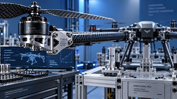
Carbon fiber composites are often selected because they can offer excellent directional stiffness and strength at low mass. That advantage is real, especially for long arms, booms, wing skins, and spars where bending stiffness drives flight behavior. But composite performance depends heavily on fiber orientation, laminate schedule, resin system, consolidation quality, void content, edge finishing, and the way loads enter the part. A tube designed primarily for axial stiffness is not automatically suitable for local clamping or bolted attachment.
Aluminum remains practical for many UAV structures because it is familiar to machine, relatively easy to inspect, repairable in some configurations, and well suited to complex brackets and precision interfaces. Its limitation is not simply weight. The evaluation question is whether the geometry can avoid stress concentration around pockets, sharp internal corners, threaded holes, and abrupt section changes. Thin machined sections may also distort during manufacture, affecting motor alignment or assembly repeatability.
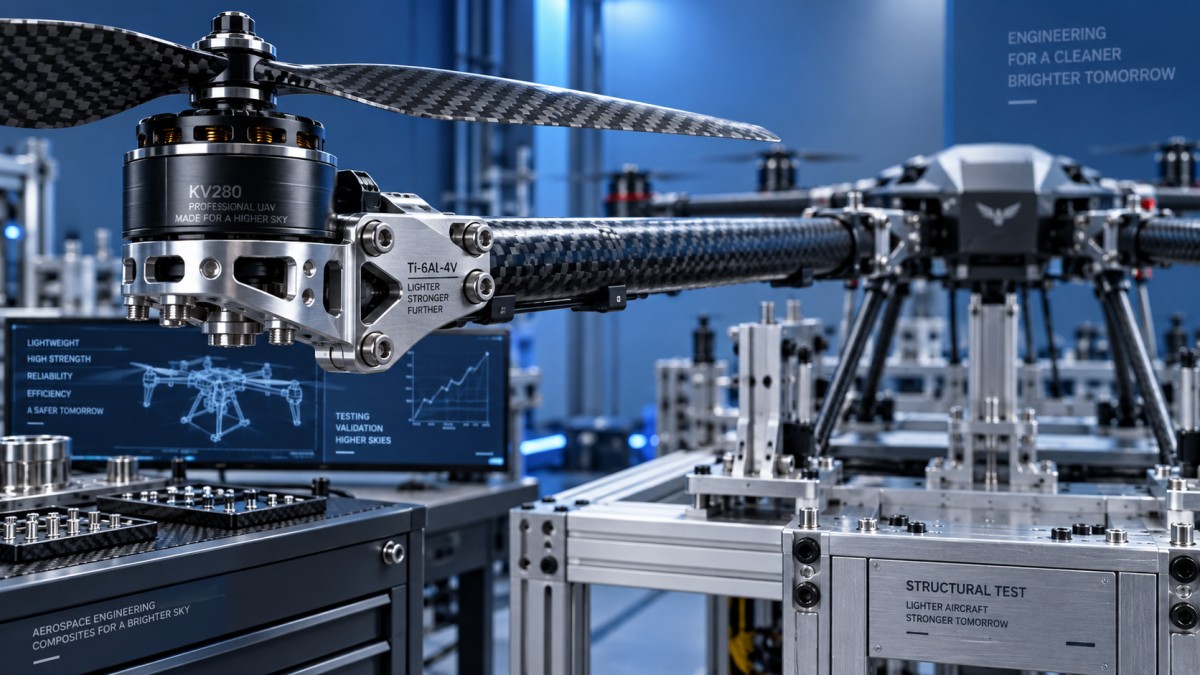
Titanium can be compelling where corrosion resistance, high local bearing loads, or temperature resistance justify its cost and machining difficulty. It is often more logical as a localized fitting, insert, hinge, or high-load joint component than as a wholesale replacement for aluminum. Hybrid construction is frequently the more rational answer: composite members for efficient spanwise stiffness, metallic fittings for concentrated loads, and carefully designed isolation at the interface.
Stiffness Often Determines Flight Quality Before Strength Does
A structural component can be strong enough to avoid fracture yet still be unsuitable because it flexes too much. Excess deflection changes motor alignment, propeller clearance, camera pointing stability, antenna orientation, and control-loop behavior. In multirotor platforms, structural modes can interact with propulsion vibration and flight-controller filtering. That interaction is not always obvious in CAD. A frame that appears rigid in a static assembly may exhibit a problematic resonance once motors, propellers, battery mass, wiring, and payload hardware are installed.
The practical response is to request more than material certificates and tensile values. For critical parts, evaluators should review stiffness assumptions, modal analysis where available, and test conditions that resemble the intended assembly. A bare arm test is informative, but it does not fully represent an arm fitted with a motor, cable routing, fasteners, and a real joint at the fuselage. For payload-carrying UAVs, it is wise to define allowable displacement or angular movement at the payload interface, not merely a safety factor on the main frame.
Fatigue Life Depends on Details Suppliers May Not Put on a Datasheet
Fatigue assessment is where marketing language becomes particularly unhelpful. Statements such as “high fatigue resistance” do not reveal the stress range, load ratio, cycle count, surface condition, temperature, specimen geometry, or failure criterion used in testing. A fatigue claim without test context should be treated as a prompt for questions, not as qualification evidence.
For metallic parts, fatigue performance is influenced by machining marks, burrs, residual stress, coatings, edge radii, hole quality, and assembly preload. A well-designed radius can matter more than changing to a more expensive alloy. Threaded holes near bending loads deserve special scrutiny; where feasible, a through-fastener, bushing, or dedicated insert may produce a more predictable joint.
Composite fatigue behavior is different. Repeated loading may produce matrix cracking, delamination, fiber-matrix debonding, or progressive damage around holes and bonded inserts before a visible fracture occurs. Impact damage is another concern. A composite boom that survives a field strike may retain its shape while carrying internal damage that changes its remaining life. Inspection plans should therefore match the failure mode. Visual inspection alone may be adequate for some cosmetic panels, but not necessarily for primary composite load paths.
There is no universal cycle target for all UAVs. A short-life prototype and a fleet aircraft intended for repeated commercial deployment should not be qualified to the same assumptions. The important step is to convert expected missions into representative cycles: takeoff and landing events, maneuver spectra, vibration exposure, folding operations, payload swaps, and transport handling. If those assumptions are not documented, a fatigue-life statement is difficult to interpret.
The Joint Is Usually the Part to Design First
Many failures in UAV aerospace structural parts occur at transitions between materials or manufacturing processes. Carbon fiber joined to aluminum can create galvanic corrosion risk in the presence of moisture unless the interface is isolated appropriately. Adhesive bonding can distribute load efficiently, but it demands controlled surface preparation, bond-line management, cure control, and a defensible inspection approach. Bolted joints are easier to disassemble, yet they introduce bearing stress, clamp-load variation, and potential fretting.
Folding arms deserve special caution. They combine repeated motion, locking accuracy, wear, vibration, and often high bending loads. A hinge that feels tight on a new sample may loosen after repeated use if tolerances, coatings, bushing materials, or preload retention are not properly controlled. Evaluators should request a clear definition of allowable play, locking method, service inspection interval, and replacement procedure. A lightweight folding mechanism is not an advantage if it turns airframe alignment into a maintenance variable.
Manufacturing Capability Must Be Verified at the Feature Level
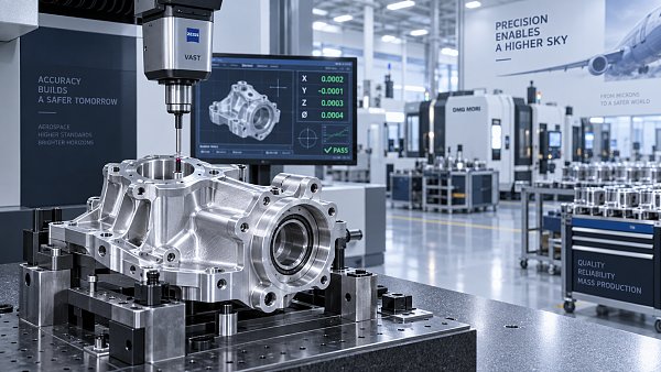
“Aerospace capable” is too broad to qualify a supplier. The relevant question is whether the supplier can repeatedly manufacture the exact features that matter to the design. For a machined aluminum motor mount, that may mean flatness, concentricity, hole-position tolerance, controlled edge breaks, and traceable surface treatment. For a composite tube, the meaningful questions may involve fiber type, ply orientation, wall-thickness consistency, resin system, cure process, insert bonding method, and the inspection used to detect voids or delamination.
AS9100 certification may be relevant when a program requires it, but certification alone does not prove that a specific part meets its structural or fatigue requirements. Likewise, a first article can demonstrate geometry without proving long-term durability. Qualification evidence should be proportional to risk: dimensional inspection for low-consequence covers, more rigorous material, process, and load validation for primary flight structure.
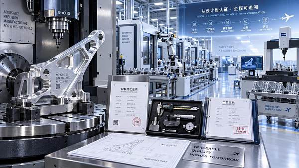
Traceability should be practical rather than ceremonial. At minimum, teams should be able to connect a delivered structural part to its drawing revision, material or laminate definition, manufacturing batch, inspection record, and any approved deviation. This becomes essential when a field issue appears months later and engineering needs to determine whether it is a design issue, a process shift, or an isolated manufacturing defect.
A Better Evaluation Package Reduces Qualification Surprises
The most effective procurement packages make technical expectations measurable. Instead of asking for “high-strength UAV arms,” specify the load interfaces, allowable mass, target stiffness or displacement limits where known, environmental conditions, surface finish requirements, assembly torque constraints, inspection criteria, and required documentation. If the design is still developing, identify which values are provisional. That is better than presenting uncertain targets as fixed requirements and discovering late that they cannot be produced economically.
A sensible review of potential suppliers can include:
- Material and process documentation tied to the actual proposed part, not a generic capability brochure.
- Dimensional inspection methods for critical interfaces and a clear approach to nonconforming parts.
- Evidence of how inserts, bonded joints, fasteners, and corrosion-sensitive material combinations are controlled.
- A defined sampling or validation plan for first production and subsequent lots.
- Communication discipline when design changes, substitutions, or process deviations are proposed.
This is where data-driven benchmarking is more valuable than broad supplier claims. TechStat Vanguard’s position is straightforward: engineering decisions improve when parameters are comparable, test conditions are visible, and tolerances are stated rather than implied. For UAV structures, that means looking past a headline tensile value and examining the evidence around the finished component, its interfaces, and its expected operating life.
The right structural choice is rarely the lightest or strongest part in isolation. It is the part whose behavior remains predictable after manufacture, assembly, vibration, weather exposure, maintenance, and repeated missions. If a supplier cannot explain how those conditions affect the proposed design, the evaluation is not finished—even if the quotation and datasheet look convincing.
Search News
Hot Articles
- Carbon Fiber StructuresHow to Specify Aerospace Carbon Fiber Assemblies for Lightweight, Load-Bearing PartsJul 11, 2026
- Machine VisionXiaomi, Alibaba DAMO Academy Drive Open-Source Robotics Model Ecosystem, Lowering Algorithm Development Barriers for Overseas SMEs Adopting Chinese Robotics SolutionsMar 30, 2026
- Cobots & ArmsShanxi 'AI+' Conference Showcases Embodied Intelligence with Multinational Buyer Engagement: Key Industry ImplicationsMar 30, 2026
Popular Tags
Recommended News
 Jul 11, 2026How to Specify Aerospace Carbon Fiber Assemblies for Lightweight, Load-Bearing PartsAerospace carbon fiber assemblies: learn how to specify laminate design, load data, joining methods, and inspection controls for lighter, reliable load-bearing aerospace parts.Elena Rostova (UAV Systems Researcher)
 Mar 30, 2026Xiaomi, Alibaba DAMO Academy Drive Open-Source Robotics Model Ecosystem, Lowering Algorithm Development Barriers for Overseas SMEs Adopting Chinese Robotics SolutionsXiaomi & Alibaba DAMO Academy's open-source robotics models lower algorithm barriers for global SMEs. Boost efficiency in manufacturing, logistics & smart retail with ROS 2 compatible solutions.TSV Data Lab
 Mar 30, 2026Shanxi 'AI+' Conference Showcases Embodied Intelligence with Multinational Buyer Engagement: Key Industry ImplicationsShanxi 'AI+' Conference highlights embodied intelligence with Tesla, Ubtech & Jiantao showcasing multimodal robotics. 40+ global buyers validated tech on-site, creating new B2B channels for industrial automation & AI solutions.Chen Wei (Automation Lead Engineer)
 Mar 30, 2026Zhongguancun Unveils 6G Integrated Sensing-Computing-Intelligence Platform to Empower Embodied Robots for Global Industrial ApplicationsZhongguancun's new 6G platform revolutionizes industrial robotics with <10ms latency, empowering global automotive, logistics & port automation. Discover how this tech boosts China's smart manufacturing exports.TSV Data Lab
 Mar 30, 2026Mech-Mind Tianjin Embodied Intelligence R&D and Production Base Goes Live, Cutting Delivery Time by 20%–30% for Global Customized AMR+Vision SolutionsMech-Mind's Tianjin AMR+Vision production base cuts delivery time by 20%-30% for欧美 & Latin American markets. Discover how this PLd-certified facility accelerates customized robotics solutions for smart manufacturing and logistics.Chen Wei (Automation Lead Engineer)
 Mar 30, 2026Boao Forum Reveals 'Co-evolution of Big and Small Brains' Trend in Humanoid Robots, China's Embodied Intelligence Accelerates Adaptation to Overseas Manufacturing Service ScenariosDiscover how China's humanoid robots, featuring 'Co-evolution of Big and Small Brains,' are revolutionizing global manufacturing. Learn about Embodied Tian Gong 3.0's ISO compliance and overseas deployment at Boao Forum 2026.Chen Wei (Automation Lead Engineer)
 Mar 30, 2026China Railway Industrial Secures Patent for Embodied Robotics in Material Handling, Boosting High-Precision Delivery Capabilities for Overseas Infrastructure and Manufacturing ProjectsChina Railway Industrial's new patent for embodied robotics in material handling boosts high-precision delivery for global infrastructure & manufacturing. Discover how this innovation enhances logistics accuracy in automotive, rail transit & EPC projects.Chen Wei (Automation Lead Engineer)
 Sep 18, 2026Selecting UAV Aerospace Structural Parts for Strength, Weight, and Fatigue LifeUAV aerospace structural parts guide: compare strength, weight, stiffness, fatigue life, joints, and traceability to select reliable flight-ready components.Elena Rostova (UAV Systems Researcher)
 Sep 17, 2026Selecting Commercial Drone Payloads for European Inspection ProjectsCommercial drone payloads Europe: learn how to select RGB, thermal and LiDAR systems for compliant, reliable inspection data and better project outcomes.Elena Rostova (UAV Systems Researcher)
 Sep 16, 2026Machining Tolerance Validation: How to Verify Critical Dimensions Before Production ReleaseMachining tolerance analysis validation: verify critical dimensions, measurement systems, process capability, and tolerance stacks before production release.Dr. Marcus Vance
 Sep 15, 2026AGV Tape Guidance vs Laser Navigation: Which Fits Your Warehouse Layout?AGV tape guidance comparison: discover how tape and laser navigation fit changing warehouse layouts, docking needs, floor conditions, maintenance, and route flexibility.Chen Wei (Automation Lead Engineer)
 Sep 14, 2026How Point Cloud Analytics Improves Asset Inspection Workflows Across GCC ProjectsPoint cloud analytics GCC helps project leaders improve asset inspections with accurate change detection, safer workflows, and faster maintenance decisions.TSV Data Lab
 Sep 13, 2026How Aerospace Manufacturers Can Build a Digital Thread From Design to Certified ProductionDigital manufacturing for aerospace: learn how to build a traceable digital thread from design through certified production, supplier control, and audit-ready compliance.Victor Lin (Chief Software Architect)
 Sep 12, 2026How to Select a Thermal Sensor for Mapping Drones in Surveying ProjectsMapping drone thermal sensor selection made simple: compare GSD, radiometric data, NETD, calibration, and workflow fit for accurate, survey-ready thermal maps.Elena Rostova (UAV Systems Researcher)
 Sep 11, 2026Integrating Photogrammetry Workflows into Digital Twin Projects Without Data BottlenecksPhotogrammetry workflow integration for digital twins: learn how to streamline capture, validation, versioning, and delivery to prevent data bottlenecks.Victor Lin (Chief Software Architect)
 Sep 10, 2026Hard-Tech Supply Chain Procurement: Qualifying Suppliers to Cut Lead-Time RiskHard-tech supply chain procurement guide: qualify suppliers with proven process, traceability, capacity, and change control to reduce lead-time risk.Chen Wei (Automation Lead Engineer)
 Sep 09, 2026Industrial Application Notes: Cost Factors That Shape Automation Project BudgetsIndustrial application notes cost factors explained: uncover the engineering, safety, integration, and commissioning variables that shape accurate automation budgets.Victor Lin (Chief Software Architect)
 Sep 08, 2026Supplier Discovery for Sourcing: How Buyers Can Verify Capability and Supply RiskSupplier discovery for sourcing: learn how to verify supplier capability, traceability, quote assumptions, and supply risk before placing production orders.TSV Data Lab
 Sep 07, 2026What Determines Process Control Systems Pricing? A Buyer’s Cost GuideProcess control systems pricing explained: compare hardware, engineering, integration, cybersecurity, validation, and lifecycle costs to choose the right-value solution.Victor Lin (Chief Software Architect)
 Sep 07, 2026AMR Robots in ASEAN: Which Industries Are Adopting Them—and Why?AMR robots ASEAN adoption is accelerating in electronics, automotive, warehousing, healthcare, and cold chain. Explore use cases, risks, and deployment insights.Chen Wei (Automation Lead Engineer)
 Sep 05, 2026How to Evaluate Supplier Qualification Support Tools for Industrial Procurement TeamsSupplier qualification support tools help industrial procurement teams verify technical evidence, manage risk, and make defensible supplier approvals. Learn what to evaluate.Victor Lin (Chief Software Architect)
 Sep 04, 2026Grinding Tolerance Analysis: How to Set Realistic Limits for Precision PartsGrinding tolerance analysis explains how to set realistic limits for precision parts, balance fit, geometry, process capability, and inspection for reliable performance.Dr. Marcus Vance
 Sep 03, 2026Warehouse Automation Strategies to Increase Storage Capacity Without ExpansionWarehouse automation space saving strategies help unlock vertical capacity, optimize slotting, and improve storage density without costly building expansion.Victor Lin (Chief Software Architect)
 Sep 02, 2026What Should Buyers Evaluate When Choosing a Hybrid VTOL UAV Factory?Hybrid VTOL UAV factory selection guide: evaluate mission fit, production traceability, payload integration, support, and total ownership costs before procurement.Elena Rostova (UAV Systems Researcher)