Aerospace Carbon Fiber Molding Process Explained: Steps, Materials, and Common Defects
Publication Date
author
Understanding the aerospace carbon fiber molding process starts with a practical question: how does a lightweight laminate become a flight-critical structure with repeatable strength, stiffness, and dimensional accuracy?
That question matters more now because aerospace programs, UAV platforms, and advanced industrial supply chains are under pressure to reduce mass without adding uncertainty.
In that environment, process data matters more than marketing language. A reliable part is not defined by broad claims, but by fiber placement control, resin behavior, cure stability, and defect rate.
For any technical review, the aerospace carbon fiber molding process links material science, tooling discipline, inspection practice, and supplier capability into one measurable manufacturing system.
Why the process deserves close attention
Carbon fiber composites are used because they deliver high specific strength and stiffness, corrosion resistance, and design flexibility for complex geometries.
Yet the same material system can produce very different outcomes if molding parameters drift.
A small change in resin content, vacuum integrity, debulk quality, or cure temperature can alter void content, interlaminar bonding, and final thickness.
This is exactly why data-driven evaluation has become central to aerospace sourcing. TechStat Vanguard’s approach of filtering noise through measurable engineering criteria fits this topic naturally.
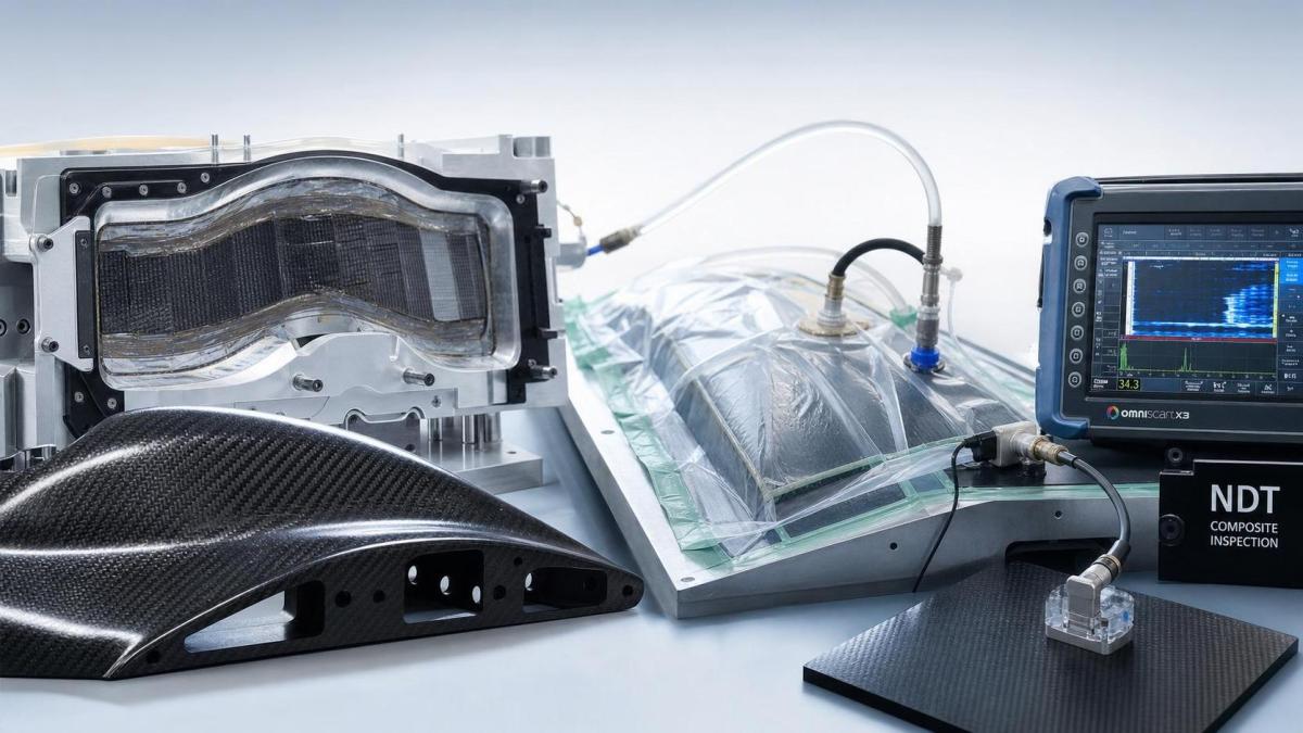
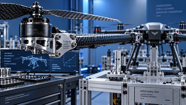
The image should represent the relationship between layup, vacuum bagging, autoclave curing, and defect inspection.
What the aerospace carbon fiber molding process actually includes
The aerospace carbon fiber molding process is not one single method. It is a family of tightly controlled forming and curing routes.
Common methods include prepreg layup with autoclave curing, out-of-autoclave vacuum curing, resin transfer molding, compression molding, and filament winding for specific structures.
In aerospace applications, prepreg systems remain dominant for primary and secondary structures that need high laminate quality and traceable performance.
Simple descriptions often stop at “layup and cure,” but actual evaluation should follow the entire path from material storage to final non-destructive inspection.
Core production steps
- Material receiving and freezer storage for prepreg shelf-life control.
- Tool preparation, release treatment, and mold surface verification.
- Ply cutting, orientation marking, and kitting by laminate schedule.
- Layup, local reinforcement placement, and periodic debulking.
- Vacuum bag assembly with bleeder, breather, and seal integrity checks.
- Cure under defined heat and pressure profile.
- Demolding, trimming, drilling, and edge finishing.
- Inspection through ultrasonic testing, dimensional checks, and record review.
Material choices that shape final performance
Material selection in the aerospace carbon fiber molding process is rarely about fiber alone. The fiber, resin, core, and auxiliary materials must work as a system.
High-strength carbon fiber may favor impact tolerance and general structural use. High-modulus grades may improve stiffness, but they can reduce strain-to-failure margins.
Epoxy remains the standard resin in many aerospace programs because of balanced mechanical performance, environmental resistance, and established certification pathways.
For sandwich structures, honeycomb or foam cores add stiffness at low weight, but they also introduce bonding and moisture-management challenges.
A supplier that cannot explain these interactions clearly usually lacks mature process ownership.
Where common defects come from
Most defects in the aerospace carbon fiber molding process are not random. They usually trace back to a limited number of control failures.
Voids often result from trapped air, poor vacuum, unstable resin flow, or incomplete compaction. Even low void content can weaken compression and fatigue behavior.
Delamination may begin with contamination, ply bridging, handling damage, or local cure mismatch. It can remain hidden until ultrasonic inspection or service loading.
Wrinkles and fiber waviness are especially critical because they reduce load-carrying efficiency along the intended fiber direction.
Resin-rich and resin-starved zones point to poor layup discipline, uneven pressure transmission, or incorrect consumable setup.
Dimensional deviation can emerge from tool distortion, thermal expansion mismatch, spring-in effects, or trimming variation.
Defects worth tracking closely
- Voids and porosity that reduce laminate density and compressive strength.
- Delamination between plies or skin-to-core interfaces.
- Wrinkles, bridging, and fiber misalignment in contoured areas.
- Dry spots or incomplete impregnation in thick sections.
- Foreign object inclusion and surface contamination.
- Thickness variation and poor hole quality after machining.
How industry teams usually evaluate process capability
A useful review goes beyond asking whether a supplier can mold carbon fiber parts. The real question is whether the aerospace carbon fiber molding process stays stable across lots, geometries, and production scale.
That means checking evidence, not presentation quality.
Practical indicators
- Documented cure cycles with actual temperature and pressure records.
- Material traceability from incoming roll to final serial number.
- Controlled freezer, thaw, and out-time management for prepreg.
- Qualification panels linked to laminate design and defect thresholds.
- Ultrasonic inspection standards and acceptance criteria.
- Evidence of repeatability after trimming, drilling, and bonding.
This is where a TSV-style benchmarking mindset becomes valuable. Parameters such as void content, thickness tolerance, fiber volume fraction, and fatigue retention reveal far more than generic quality claims.
Typical application contexts across the broader industrial landscape
Although aerospace sets the strictest baseline, the aerospace carbon fiber molding process also influences adjacent sectors that borrow aerospace-grade design logic.
Commercial UAV airframes use many of the same laminate principles, especially when endurance, payload efficiency, and vibration behavior matter.
Satellite structures, radomes, rotor components, fairings, and lightweight automation assemblies all benefit from lessons developed in certified aerospace environments.
From a cross-industry perspective, this process also affects tooling strategy, CNC finishing requirements, adhesive bonding plans, and inspection infrastructure.
Questions that sharpen the next decision
When comparing suppliers or validating internal production, several questions quickly separate a controlled process from a risky one.
- Is the chosen molding route aligned with part geometry, rate, and certification target?
- Are material choices justified by structural loads and environmental exposure?
- Which defects occur most often, and what closed-loop correction data exists?
- How are cure records, NDT results, and dimensional reports connected?
- Can the same aerospace carbon fiber molding process scale without changing laminate quality?
Those questions do not require dramatic conclusions. They create a disciplined framework for screening process maturity, qualification risk, and long-term supply stability.
A sensible next step is to map part-critical requirements against actual process evidence: cure data, defect history, inspection capability, and tolerance performance. That turns composite sourcing into an engineering decision rather than a messaging exercise.
Search News
Hot Articles
- Carbon Fiber StructuresHow to Specify Aerospace Carbon Fiber Assemblies for Lightweight, Load-Bearing PartsJul 11, 2026
- Machine VisionXiaomi, Alibaba DAMO Academy Drive Open-Source Robotics Model Ecosystem, Lowering Algorithm Development Barriers for Overseas SMEs Adopting Chinese Robotics SolutionsMar 30, 2026
- Cobots & ArmsShanxi 'AI+' Conference Showcases Embodied Intelligence with Multinational Buyer Engagement: Key Industry ImplicationsMar 30, 2026
Popular Tags
Recommended News
 Jul 11, 2026How to Specify Aerospace Carbon Fiber Assemblies for Lightweight, Load-Bearing PartsAerospace carbon fiber assemblies: learn how to specify laminate design, load data, joining methods, and inspection controls for lighter, reliable load-bearing aerospace parts.Elena Rostova (UAV Systems Researcher)
 Mar 30, 2026Xiaomi, Alibaba DAMO Academy Drive Open-Source Robotics Model Ecosystem, Lowering Algorithm Development Barriers for Overseas SMEs Adopting Chinese Robotics SolutionsXiaomi & Alibaba DAMO Academy's open-source robotics models lower algorithm barriers for global SMEs. Boost efficiency in manufacturing, logistics & smart retail with ROS 2 compatible solutions.TSV Data Lab
 Mar 30, 2026Shanxi 'AI+' Conference Showcases Embodied Intelligence with Multinational Buyer Engagement: Key Industry ImplicationsShanxi 'AI+' Conference highlights embodied intelligence with Tesla, Ubtech & Jiantao showcasing multimodal robotics. 40+ global buyers validated tech on-site, creating new B2B channels for industrial automation & AI solutions.Chen Wei (Automation Lead Engineer)
 Mar 30, 2026Zhongguancun Unveils 6G Integrated Sensing-Computing-Intelligence Platform to Empower Embodied Robots for Global Industrial ApplicationsZhongguancun's new 6G platform revolutionizes industrial robotics with <10ms latency, empowering global automotive, logistics & port automation. Discover how this tech boosts China's smart manufacturing exports.TSV Data Lab
 Mar 30, 2026Mech-Mind Tianjin Embodied Intelligence R&D and Production Base Goes Live, Cutting Delivery Time by 20%–30% for Global Customized AMR+Vision SolutionsMech-Mind's Tianjin AMR+Vision production base cuts delivery time by 20%-30% for欧美 & Latin American markets. Discover how this PLd-certified facility accelerates customized robotics solutions for smart manufacturing and logistics.Chen Wei (Automation Lead Engineer)
 Mar 30, 2026Boao Forum Reveals 'Co-evolution of Big and Small Brains' Trend in Humanoid Robots, China's Embodied Intelligence Accelerates Adaptation to Overseas Manufacturing Service ScenariosDiscover how China's humanoid robots, featuring 'Co-evolution of Big and Small Brains,' are revolutionizing global manufacturing. Learn about Embodied Tian Gong 3.0's ISO compliance and overseas deployment at Boao Forum 2026.Chen Wei (Automation Lead Engineer)
 Mar 30, 2026China Railway Industrial Secures Patent for Embodied Robotics in Material Handling, Boosting High-Precision Delivery Capabilities for Overseas Infrastructure and Manufacturing ProjectsChina Railway Industrial's new patent for embodied robotics in material handling boosts high-precision delivery for global infrastructure & manufacturing. Discover how this innovation enhances logistics accuracy in automotive, rail transit & EPC projects.Chen Wei (Automation Lead Engineer)
 Sep 20, 2026Autonomous Navigation Pricing: Cost Drivers and Budget Benchmarks for AMR ProjectsAutonomous navigation price explained: compare AMR cost drivers, software, sensors, integration, safety, and lifecycle budgets to build a scalable project plan.Chen Wei (Automation Lead Engineer)
 Sep 19, 2026How to Scope Automation Integration Services for Multi-System Factory ProjectsAutomation integration services: learn how to scope multi-system factory projects with clear workflows, interface contracts, safety boundaries, and acceptance criteria.Victor Lin (Chief Software Architect)
 Sep 18, 2026Selecting UAV Aerospace Structural Parts for Strength, Weight, and Fatigue LifeUAV aerospace structural parts guide: compare strength, weight, stiffness, fatigue life, joints, and traceability to select reliable flight-ready components.Elena Rostova (UAV Systems Researcher)
 Sep 17, 2026Selecting Commercial Drone Payloads for European Inspection ProjectsCommercial drone payloads Europe: learn how to select RGB, thermal and LiDAR systems for compliant, reliable inspection data and better project outcomes.Elena Rostova (UAV Systems Researcher)
 Sep 16, 2026Machining Tolerance Validation: How to Verify Critical Dimensions Before Production ReleaseMachining tolerance analysis validation: verify critical dimensions, measurement systems, process capability, and tolerance stacks before production release.Dr. Marcus Vance
 Sep 15, 2026AGV Tape Guidance vs Laser Navigation: Which Fits Your Warehouse Layout?AGV tape guidance comparison: discover how tape and laser navigation fit changing warehouse layouts, docking needs, floor conditions, maintenance, and route flexibility.Chen Wei (Automation Lead Engineer)
 Sep 14, 2026How Point Cloud Analytics Improves Asset Inspection Workflows Across GCC ProjectsPoint cloud analytics GCC helps project leaders improve asset inspections with accurate change detection, safer workflows, and faster maintenance decisions.TSV Data Lab
 Sep 13, 2026How Aerospace Manufacturers Can Build a Digital Thread From Design to Certified ProductionDigital manufacturing for aerospace: learn how to build a traceable digital thread from design through certified production, supplier control, and audit-ready compliance.Victor Lin (Chief Software Architect)
 Sep 12, 2026How to Select a Thermal Sensor for Mapping Drones in Surveying ProjectsMapping drone thermal sensor selection made simple: compare GSD, radiometric data, NETD, calibration, and workflow fit for accurate, survey-ready thermal maps.Elena Rostova (UAV Systems Researcher)
 Sep 11, 2026Integrating Photogrammetry Workflows into Digital Twin Projects Without Data BottlenecksPhotogrammetry workflow integration for digital twins: learn how to streamline capture, validation, versioning, and delivery to prevent data bottlenecks.Victor Lin (Chief Software Architect)
 Sep 10, 2026Hard-Tech Supply Chain Procurement: Qualifying Suppliers to Cut Lead-Time RiskHard-tech supply chain procurement guide: qualify suppliers with proven process, traceability, capacity, and change control to reduce lead-time risk.Chen Wei (Automation Lead Engineer)
 Sep 09, 2026Industrial Application Notes: Cost Factors That Shape Automation Project BudgetsIndustrial application notes cost factors explained: uncover the engineering, safety, integration, and commissioning variables that shape accurate automation budgets.Victor Lin (Chief Software Architect)
 Sep 08, 2026Supplier Discovery for Sourcing: How Buyers Can Verify Capability and Supply RiskSupplier discovery for sourcing: learn how to verify supplier capability, traceability, quote assumptions, and supply risk before placing production orders.TSV Data Lab
 Sep 07, 2026What Determines Process Control Systems Pricing? A Buyer’s Cost GuideProcess control systems pricing explained: compare hardware, engineering, integration, cybersecurity, validation, and lifecycle costs to choose the right-value solution.Victor Lin (Chief Software Architect)
 Sep 07, 2026AMR Robots in ASEAN: Which Industries Are Adopting Them—and Why?AMR robots ASEAN adoption is accelerating in electronics, automotive, warehousing, healthcare, and cold chain. Explore use cases, risks, and deployment insights.Chen Wei (Automation Lead Engineer)
 Sep 05, 2026How to Evaluate Supplier Qualification Support Tools for Industrial Procurement TeamsSupplier qualification support tools help industrial procurement teams verify technical evidence, manage risk, and make defensible supplier approvals. Learn what to evaluate.Victor Lin (Chief Software Architect)
 Sep 04, 2026Grinding Tolerance Analysis: How to Set Realistic Limits for Precision PartsGrinding tolerance analysis explains how to set realistic limits for precision parts, balance fit, geometry, process capability, and inspection for reliable performance.Dr. Marcus Vance