Electromagnetic Interference Testing Explained: Standards, Test Setups, and Failure Points
Publication Date
author
Why does electromagnetic interference testing matter so early in product validation?
Electromagnetic interference testing is not only a certification checkpoint. It is a design reality check for products expected to work around motors, radios, inverters, sensors, and dense digital electronics.
In practical terms, EMI failures rarely stay inside the lab. They often return as unstable communication, false triggering, degraded sensor readings, or unexpected shutdowns in the field.
That is why electromagnetic interference testing matters across industrial controls, UAV electronics, edge devices, medical subsystems, and precision manufacturing equipment.
The real value is not a passing logo on a report. The real value is proving that emissions stay controlled and immunity remains strong under realistic operating stress.
This data-first view also aligns with how TechStat Vanguard evaluates hard-tech performance. Parameters, thresholds, and repeatable test evidence are more useful than broad marketing claims.
When teams treat electromagnetic interference testing as a late-stage formality, schedules tighten, redesign loops multiply, and supplier discussions become harder to manage with confidence.
What exactly does electromagnetic interference testing cover?
A common misunderstanding is that EMI testing only checks whether a device is “noisy.” In reality, the scope is broader and usually splits into two linked questions.
First, how much unwanted energy does the product emit through cables or into free space? Second, how well does it keep working when outside electromagnetic energy is applied?
Those two sides are usually described as emissions and immunity. Both matter, because a product can be quiet enough to pass one limit and still be too fragile to survive real deployment.
In mixed industrial environments, the risk sources are diverse. Variable frequency drives, switching power supplies, high-speed clocks, antennas, long cable runs, and poor grounding all contribute.
More sensitive platforms face an even smaller margin. Think autonomous flight controllers, machine vision systems, LiDAR modules, or tightly packed IoT gateways with multiple wireless interfaces.
A useful way to frame electromagnetic interference testing is shown below.
This broader perspective helps explain why electromagnetic interference testing is often tied to both compliance and operational reliability.
Which standards usually drive the test plan?
Searches for standards often start with one simple question: which document actually applies to the product on the bench? The answer depends on market, environment, and function.
For commercial and industrial electronics, CISPR and IEC families are common starting points. In North America, FCC rules may also define emissions requirements for digital devices.
Industrial equipment frequently references IEC 61000 series documents. These cover emissions limits and immunity methods such as ESD, EFT, surge, conducted RF, and radiated RF testing.
Aviation, defense, and transport platforms usually follow more specialized requirements. RTCA DO-160, MIL-STD families, and automotive EMC standards introduce different severity levels and configurations.
What matters is not memorizing acronyms. It is mapping the product’s actual use condition to the correct standard boundary, frequency range, limit class, and performance criteria.
In real projects, the better question is often this: what environment must the product survive, and what evidence will regulators, customers, or internal auditors expect to see?
- Office and light commercial devices usually focus on civilian emissions control.
- Factory equipment must handle stronger electrical noise and longer cable exposure.
- Aerospace and UAV electronics demand tighter scrutiny under complex electromagnetic environments.
- Connected sensors and edge AI hardware need careful coexistence planning with wireless modules.
That insistence on exact applicability mirrors TSV’s wider approach. Sound decisions begin with traceable standards, not with generic claims that a device is “EMI safe.”
What does a credible EMI test setup look like in practice?
A strong lab setup does more than produce charts. It recreates the product’s operating condition with enough control that results are repeatable and useful for engineering decisions.
For conducted emissions, the setup often includes a LISN, defined cable lengths, grounding references, and stable operating modes. Small deviations can shift the result more than expected.
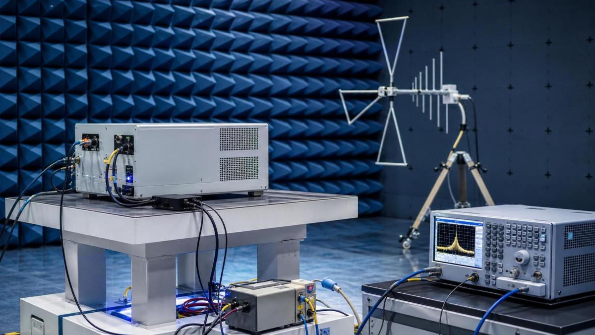
Radiated emissions work usually relies on calibrated antennas, a semi-anechoic chamber or open area site, turntable positioning, and worst-case orientation checks.
Immunity testing adds another layer. The product must stay functionally active while RF fields, fast transients, surges, or electrostatic discharges are applied in controlled steps.
The weak point in many programs is not equipment quality. It is test mode definition. If the device is idle, muted, or only partially loaded, failures may stay hidden.
More reliable electromagnetic interference testing usually includes realistic firmware states, active communication ports, worst-case current draw, and representative cable assemblies.
Before formal testing starts, these checks prevent expensive ambiguity.
- Confirm the exact hardware revision and firmware build.
- Define pass or fail behavior before exposure begins.
- Document cable types, lengths, connectors, and grounding points.
- Run pre-scan checks to identify likely peak frequencies.
- Keep support equipment outside the critical measurement path when possible.
When these details are controlled, electromagnetic interference testing becomes a troubleshooting tool, not just an external requirement.
Where do failures usually come from, even in well-designed products?
Most failures are not caused by one dramatic flaw. They result from several ordinary decisions interacting badly at high frequency.
PCB layout is a frequent culprit. Return path breaks, poor stack-up choices, long high-speed traces, and weak partitioning between noisy and sensitive zones all raise risk.
Power design is another trouble area. Fast switching edges, incomplete filtering, and poorly chosen decoupling networks often create peaks that only appear under realistic load.
Cables and enclosures also deserve more attention than they usually get. An excellent board can still fail if shield termination, bonding, or connector grounding is inconsistent.
In immunity work, firmware behavior matters as much as hardware. Recovery logic, watchdog settings, error handling, and interface robustness often decide whether a disturbance becomes a reportable failure.
The pattern below appears often during electromagnetic interference testing.
How should teams judge cost, schedule, and retest risk?
The cheapest electromagnetic interference testing plan is rarely the lowest-cost project outcome. A narrow test scope can look efficient until one failure forces board changes, chamber rebooking, and shipping delays.
A better way is to divide work into design review, pre-compliance, formal certification, and failure analysis. That sequence reduces surprises and improves root-cause speed.
Pre-compliance testing is especially valuable for products with wireless functions, fast processors, long harnesses, or operation near strong electromagnetic fields.
In many sectors, the biggest hidden cost is supplier inconsistency. Cable substitutions, enclosure coating changes, or alternate power modules can shift performance after the first pass.
That is why engineering traceability matters. The same discipline TSV promotes in benchmarking also applies here: tie every result to a controlled configuration and measurable condition.
If a program is approaching certification, these questions usually separate a stable path from a risky one.
- Has the worst-case operating mode been defined and validated?
- Are component alternates frozen before final electromagnetic interference testing?
- Do pass criteria include functional performance, not only visible power-on status?
- Is there enough schedule room for one corrective iteration if needed?
These are practical control points, not paperwork details. They directly affect launch timing, audit readiness, and long-term field stability.
What is the smartest next step before booking the final lab slot?
Start by narrowing the standard set, operating environment, and failure definition. That sounds basic, but it prevents many expensive misunderstandings later.
Then build a short evidence package: schematics, layout notes, cable plan, firmware mode description, prior pre-scan data, and the exact configuration intended for test.
For products entering demanding sectors, compare lab results with realistic field stress. A narrow pass in the chamber may still be too fragile for dense industrial or aerospace environments.
Electromagnetic interference testing works best when it is treated as an engineering feedback loop. The goal is not only compliance. The goal is predictable behavior under measurable electrical stress.
That is also the wider lesson behind data-driven technical review. Clear thresholds, controlled variables, and traceable evidence make decisions faster and far more defensible.
If the next review is approaching, refine the test matrix, lock the hardware baseline, and verify worst-case use conditions before formal booking. That one step often saves the entire schedule.
Search News
Hot Articles
- Carbon Fiber StructuresHow to Specify Aerospace Carbon Fiber Assemblies for Lightweight, Load-Bearing PartsJul 11, 2026
- Machine VisionXiaomi, Alibaba DAMO Academy Drive Open-Source Robotics Model Ecosystem, Lowering Algorithm Development Barriers for Overseas SMEs Adopting Chinese Robotics SolutionsMar 30, 2026
- Cobots & ArmsShanxi 'AI+' Conference Showcases Embodied Intelligence with Multinational Buyer Engagement: Key Industry ImplicationsMar 30, 2026
Popular Tags
Recommended News
 Jul 11, 2026How to Specify Aerospace Carbon Fiber Assemblies for Lightweight, Load-Bearing PartsAerospace carbon fiber assemblies: learn how to specify laminate design, load data, joining methods, and inspection controls for lighter, reliable load-bearing aerospace parts.Elena Rostova (UAV Systems Researcher)
 Mar 30, 2026Xiaomi, Alibaba DAMO Academy Drive Open-Source Robotics Model Ecosystem, Lowering Algorithm Development Barriers for Overseas SMEs Adopting Chinese Robotics SolutionsXiaomi & Alibaba DAMO Academy's open-source robotics models lower algorithm barriers for global SMEs. Boost efficiency in manufacturing, logistics & smart retail with ROS 2 compatible solutions.TSV Data Lab
 Mar 30, 2026Shanxi 'AI+' Conference Showcases Embodied Intelligence with Multinational Buyer Engagement: Key Industry ImplicationsShanxi 'AI+' Conference highlights embodied intelligence with Tesla, Ubtech & Jiantao showcasing multimodal robotics. 40+ global buyers validated tech on-site, creating new B2B channels for industrial automation & AI solutions.Chen Wei (Automation Lead Engineer)
 Mar 30, 2026Zhongguancun Unveils 6G Integrated Sensing-Computing-Intelligence Platform to Empower Embodied Robots for Global Industrial ApplicationsZhongguancun's new 6G platform revolutionizes industrial robotics with <10ms latency, empowering global automotive, logistics & port automation. Discover how this tech boosts China's smart manufacturing exports.TSV Data Lab
 Mar 30, 2026Mech-Mind Tianjin Embodied Intelligence R&D and Production Base Goes Live, Cutting Delivery Time by 20%–30% for Global Customized AMR+Vision SolutionsMech-Mind's Tianjin AMR+Vision production base cuts delivery time by 20%-30% for欧美 & Latin American markets. Discover how this PLd-certified facility accelerates customized robotics solutions for smart manufacturing and logistics.Chen Wei (Automation Lead Engineer)
 Mar 30, 2026Boao Forum Reveals 'Co-evolution of Big and Small Brains' Trend in Humanoid Robots, China's Embodied Intelligence Accelerates Adaptation to Overseas Manufacturing Service ScenariosDiscover how China's humanoid robots, featuring 'Co-evolution of Big and Small Brains,' are revolutionizing global manufacturing. Learn about Embodied Tian Gong 3.0's ISO compliance and overseas deployment at Boao Forum 2026.Chen Wei (Automation Lead Engineer)
 Mar 30, 2026China Railway Industrial Secures Patent for Embodied Robotics in Material Handling, Boosting High-Precision Delivery Capabilities for Overseas Infrastructure and Manufacturing ProjectsChina Railway Industrial's new patent for embodied robotics in material handling boosts high-precision delivery for global infrastructure & manufacturing. Discover how this innovation enhances logistics accuracy in automotive, rail transit & EPC projects.Chen Wei (Automation Lead Engineer)
 Sep 19, 2026How to Scope Automation Integration Services for Multi-System Factory ProjectsAutomation integration services: learn how to scope multi-system factory projects with clear workflows, interface contracts, safety boundaries, and acceptance criteria.Victor Lin (Chief Software Architect)
 Sep 18, 2026Selecting UAV Aerospace Structural Parts for Strength, Weight, and Fatigue LifeUAV aerospace structural parts guide: compare strength, weight, stiffness, fatigue life, joints, and traceability to select reliable flight-ready components.Elena Rostova (UAV Systems Researcher)
 Sep 17, 2026Selecting Commercial Drone Payloads for European Inspection ProjectsCommercial drone payloads Europe: learn how to select RGB, thermal and LiDAR systems for compliant, reliable inspection data and better project outcomes.Elena Rostova (UAV Systems Researcher)
 Sep 16, 2026Machining Tolerance Validation: How to Verify Critical Dimensions Before Production ReleaseMachining tolerance analysis validation: verify critical dimensions, measurement systems, process capability, and tolerance stacks before production release.Dr. Marcus Vance
 Sep 15, 2026AGV Tape Guidance vs Laser Navigation: Which Fits Your Warehouse Layout?AGV tape guidance comparison: discover how tape and laser navigation fit changing warehouse layouts, docking needs, floor conditions, maintenance, and route flexibility.Chen Wei (Automation Lead Engineer)
 Sep 14, 2026How Point Cloud Analytics Improves Asset Inspection Workflows Across GCC ProjectsPoint cloud analytics GCC helps project leaders improve asset inspections with accurate change detection, safer workflows, and faster maintenance decisions.TSV Data Lab
 Sep 13, 2026How Aerospace Manufacturers Can Build a Digital Thread From Design to Certified ProductionDigital manufacturing for aerospace: learn how to build a traceable digital thread from design through certified production, supplier control, and audit-ready compliance.Victor Lin (Chief Software Architect)
 Sep 12, 2026How to Select a Thermal Sensor for Mapping Drones in Surveying ProjectsMapping drone thermal sensor selection made simple: compare GSD, radiometric data, NETD, calibration, and workflow fit for accurate, survey-ready thermal maps.Elena Rostova (UAV Systems Researcher)
 Sep 11, 2026Integrating Photogrammetry Workflows into Digital Twin Projects Without Data BottlenecksPhotogrammetry workflow integration for digital twins: learn how to streamline capture, validation, versioning, and delivery to prevent data bottlenecks.Victor Lin (Chief Software Architect)
 Sep 10, 2026Hard-Tech Supply Chain Procurement: Qualifying Suppliers to Cut Lead-Time RiskHard-tech supply chain procurement guide: qualify suppliers with proven process, traceability, capacity, and change control to reduce lead-time risk.Chen Wei (Automation Lead Engineer)
 Sep 09, 2026Industrial Application Notes: Cost Factors That Shape Automation Project BudgetsIndustrial application notes cost factors explained: uncover the engineering, safety, integration, and commissioning variables that shape accurate automation budgets.Victor Lin (Chief Software Architect)
 Sep 08, 2026Supplier Discovery for Sourcing: How Buyers Can Verify Capability and Supply RiskSupplier discovery for sourcing: learn how to verify supplier capability, traceability, quote assumptions, and supply risk before placing production orders.TSV Data Lab
 Sep 07, 2026What Determines Process Control Systems Pricing? A Buyer’s Cost GuideProcess control systems pricing explained: compare hardware, engineering, integration, cybersecurity, validation, and lifecycle costs to choose the right-value solution.Victor Lin (Chief Software Architect)
 Sep 07, 2026AMR Robots in ASEAN: Which Industries Are Adopting Them—and Why?AMR robots ASEAN adoption is accelerating in electronics, automotive, warehousing, healthcare, and cold chain. Explore use cases, risks, and deployment insights.Chen Wei (Automation Lead Engineer)
 Sep 05, 2026How to Evaluate Supplier Qualification Support Tools for Industrial Procurement TeamsSupplier qualification support tools help industrial procurement teams verify technical evidence, manage risk, and make defensible supplier approvals. Learn what to evaluate.Victor Lin (Chief Software Architect)
 Sep 04, 2026Grinding Tolerance Analysis: How to Set Realistic Limits for Precision PartsGrinding tolerance analysis explains how to set realistic limits for precision parts, balance fit, geometry, process capability, and inspection for reliable performance.Dr. Marcus Vance
 Sep 03, 2026Warehouse Automation Strategies to Increase Storage Capacity Without ExpansionWarehouse automation space saving strategies help unlock vertical capacity, optimize slotting, and improve storage density without costly building expansion.Victor Lin (Chief Software Architect)