Grinding Tolerance Analysis: How to Set Realistic Limits for Precision Parts
Publication Date
author
A drawing calls for a ground shaft diameter with a very narrow limit, and the request appears reasonable until the part reaches inspection. One batch measures acceptably at the center but drifts near the ends; another passes diameter checks but binds during assembly. The immediate reaction is often to tighten the grinding requirement further. That can increase rejection, cost, and lead time without resolving the functional problem.
A realistic grinding tolerance is not simply the smallest number a supplier says it can hold. It is the limit that preserves the part’s fit, motion, sealing, fatigue performance, or positional accuracy after material variation, thermal effects, grinding behavior, inspection uncertainty, and assembly stack-up are considered. Effective grinding tolerance analysis starts with the functional boundary, then works backward to a measurable and stable manufacturing specification.
Start with the failure mode, not the drawing decimal places
Grinding is often selected when a feature needs close size control, low roughness, good roundness, or reliable geometry after heat treatment. Yet different part functions demand different controls. A bearing journal, a hydraulic spool, a sealing land, a locating diameter, and a mating gear bore may all be ground, but their critical risks are not identical.
Before assigning a tolerance, define what becomes unacceptable when the feature moves away from nominal. The relevant question is not “Can this diameter be held to a few microns?” It is “At what condition does the assembly stop performing as intended?”
- Clearance-controlled fits need enough minimum clearance to avoid seizure after temperature change, coating variation, lubricant effects, or minor misalignment.
- Interference fits need sufficient minimum interference to transmit load or prevent movement, while maximum interference must not crack, distort, or overstress the mating component.
- Sealing surfaces may depend as much on roundness, waviness, and surface finish as on diameter.
- Rotating components may require control of runout, cylindricity, and concentricity relative to functional datums, rather than a tighter size tolerance alone.
- Fatigue-sensitive parts can be affected by grinding burn, residual stress, thermal damage, and surface condition even when all dimensional results pass.
This distinction matters during technical evaluation. A specification that limits diameter but ignores the geometry causing assembly friction is incomplete. Conversely, a drawing that places extreme limits on every ground surface may create an unnecessarily expensive process while failing to identify the few surfaces that genuinely govern performance.
Translate assembly requirements into a permissible part range
The most defensible tolerance begins with the mating condition. Establish the functional gap or interference range first, then allocate the available variation among all contributors. For a shaft-and-bore relationship, that includes the shaft size, bore size, form error, coating thickness where applicable, thermal expansion, and any deformation caused by mounting or loading.
Consider a shaft that must rotate freely in a bore. The minimum operating clearance must remain positive under the least favorable condition: the largest shaft, the smallest bore, relevant temperature differential, and functional surface conditions. The maximum clearance must also remain below the point where vibration, leakage, positional loss, or impact loading becomes unacceptable. Only after that operating window is established can dimensional limits be assigned to the individual parts.
Do not assume that each contributor deserves an equal share of the total assembly allowance. A heat-treated bore made in a less stable process may consume more variation than a finish-ground shaft. A plated surface may introduce thickness variation. A thin-wall part may change shape after clamping is released. Tolerance allocation should reflect the actual behavior and controllability of each feature.
A useful review exercise is to examine the two worst functional combinations, not just nominal dimensions. One condition uses all features at the extremes that produce the least clearance or greatest interference. The other tests the opposite side of the range. If either combination fails functionally, the tolerance scheme needs revision before grinding capability is discussed.
Separate size tolerance from geometric tolerance
A ground diameter can be within its upper and lower limits while still being tapered, lobed, bowed, or out of position relative to another feature. This is a recurring source of disagreement between machining teams and inspection teams: both may be correct about the measured size, but the part may still fail in service.
For example, two diameter readings taken at the middle of a shaft do not establish cylindricity. A micrometer reading at a few clock positions may not reveal lobing. A component can also meet roundness requirements at individual cross-sections but have a centerline that wanders relative to the datum axis. Where assembly depends on rotational accuracy, total indicator runout or a datum-based positional control may be more meaningful than demanding an extremely narrow diameter range.
Specify only the geometric controls that protect the function. A bearing seat may need a limited cylindricity tolerance because local high spots affect contact distribution. A long spindle may need straightness control because bow influences runout. A short locating journal may instead be governed by perpendicularity to a mounting face. Applying all possible geometric tolerances “for safety” makes inspection harder and can obscure the true acceptance criteria.
Account for the grinding process window
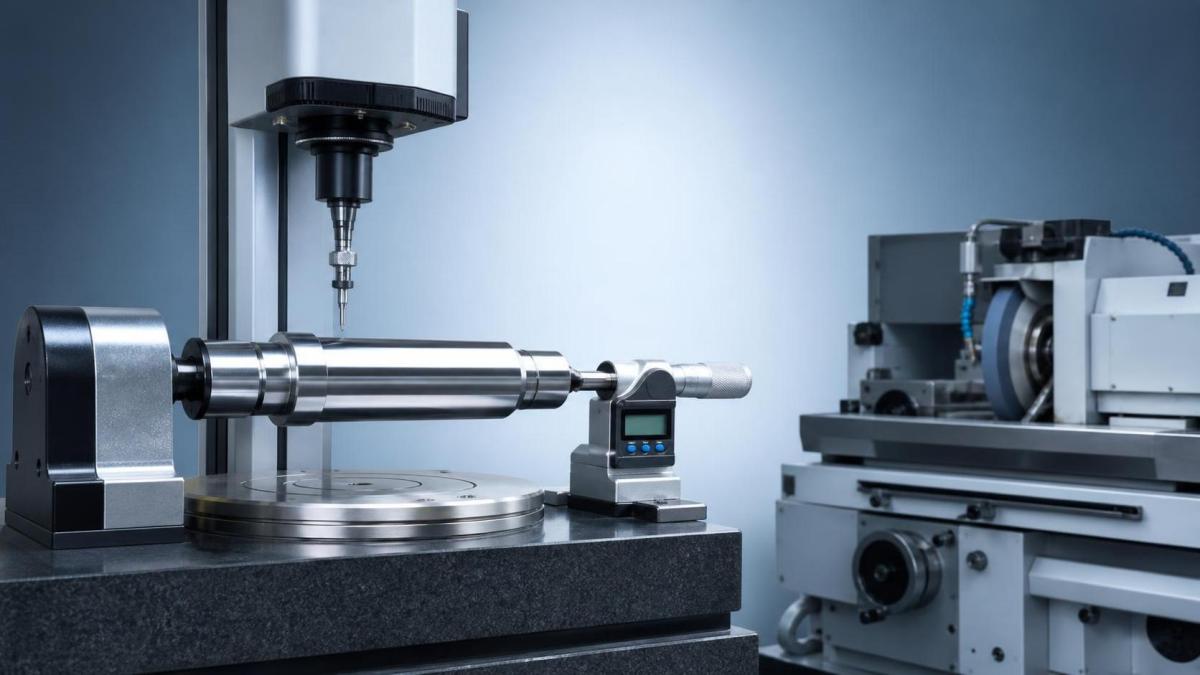
Grinding capability is influenced by much more than the machine’s stated precision. Wheel specification, wheel dressing condition, coolant delivery, workholding rigidity, part geometry, stock allowance, material hardness, and thermal stability all affect the achievable result. A tolerance that can be demonstrated on a short, rigid steel ring may not be stable on a long, slender hardened shaft or a thin-walled stainless component.
Material condition deserves early attention. Heat treatment can introduce distortion, hardness variation, retained stress, and nonuniform stock. If the allowance left for grinding is inconsistent, the wheel may remove material unevenly, and the final part can show taper, burn, or changing surface texture. Grinding a part with insufficient stock may leave pre-existing distortion untouched; excessive stock can increase cycle time and thermal load.
Questions that expose process risk
- Is the ground feature machined before or after heat treatment, coating, welding, or stress relief?
- What stock allowance is expected at the grinding operation, and how much variation can the upstream process create?
- Does the part require center support, chucking, magnetic holding, mandrel support, or a custom fixture?
- Could clamping force distort the part during grinding and allow it to spring back after release?
- Is the required tolerance applied over the full length, near shoulders, across interrupted surfaces, or only within a defined functional zone?
- Are there risks of grinding burn, microcracking, or metallurgical damage that dimensional inspection will not detect?
These questions are particularly important when evaluating quoted capability. A supplier may correctly state that it can grind to a certain dimensional range, but the technical decision should confirm whether that range applies to the specific material, length-to-diameter ratio, hardness, feature accessibility, and quantity under review.
Use a capability margin rather than accepting a one-time result
A part that passes once is not evidence that a production process can repeatedly hold the requirement. Grinding tolerances should leave practical room between normal process variation and the specification limits. The exact statistical method depends on the organization’s quality system and production context, but the underlying principle is consistent: process spread, measurement variation, and expected drift must fit inside the allowed tolerance with margin.
Capability evidence should be interpreted in context. A tightly clustered inspection report may reflect a controlled production run, but it may also represent a small sample, a newly dressed wheel, a favorable machine temperature, or measurements taken by one operator using one instrument. Ask how the process is maintained across wheel wear, setup changes, shifts, batches of material, and equipment warm-up.
Where a feature is especially critical, define the evidence expected during qualification. This may include diameter results across multiple locations, roundness or cylindricity data, surface finish measurements, runout relative to functional datums, and records showing how the feature is verified after grinding. The goal is not to create paperwork for its own sake. It is to distinguish a controlled process from a favorable single setup.
Inspection uncertainty can consume a meaningful portion of the tolerance
Inspection method selection must be part of the tolerance decision. When the permitted variation approaches the uncertainty of the measuring system, acceptance decisions become unstable. A part may appear to move in and out of tolerance because of contact force, operator technique, temperature, gauge resolution, alignment, or the number and location of readings.
A handheld micrometer may be suitable for routine diameter confirmation, but it may not prove roundness, taper over length, or form at the level required by a critical fit. Air gauging can be effective for high-volume bore or diameter assessment, while a roundness instrument, form tester, or coordinate measuring machine may be needed for specific geometric characteristics. Each method has limits; the method should match the characteristic being controlled.
Temperature is often overlooked. Precision measurements should be interpreted against the agreed reference conditions, especially for long parts or materials with appreciable thermal expansion. A part, gauge, and inspection environment that have not stabilized can produce apparent size differences that do not reflect the actual manufactured condition. This does not require turning every inspection area into a laboratory, but it does require clear handling rules when the tolerance is narrow.
When a tighter tolerance is the wrong correction
Suppose an assembly has intermittent fit problems. Tightening the shaft diameter tolerance may appear to reduce risk, yet the problem could originate in bore distortion, datum misalignment, burrs, coating variation, thermal expansion, or an inadequate chamfer. A narrower ground diameter range will not reliably correct these causes. It may merely shift the burden to the grinder and increase sorting.
The same issue appears with surface requirements. Calling for a lower roughness value does not automatically improve sealing or sliding performance. Some functions are sensitive to waviness, lay direction, or plateau characteristics rather than the average roughness value alone. Similarly, a very tight runout callout may be unnecessary when the function only requires controlled local contact, but it may be essential where a rotating seal or encoder depends on stable rotation.
Before reducing a tolerance, identify the observed failure signature. Binding near one end suggests taper, alignment, or straightness concerns. Variable insertion force can point to form variation, burrs, inconsistent coating, or unstable interference. Leakage may require an examination of surface texture and mating condition. Premature fatigue concerns require attention to thermal damage and surface integrity, not just dimensional records.
A practical release path for technical evaluation
Release the specification in a sequence that preserves traceability from function to inspection. First, document the operating limit: required clearance, interference, alignment, leakage threshold, or motion behavior. Next, create the dimensional stack-up, including all mating features and relevant environmental effects. Then identify which individual controls are necessary: size, form, orientation, runout, and surface condition.
After that, test the requirement against the proposed manufacturing route. Confirm material state, grinding allowance, workholding concept, likely sources of distortion, and the ability to inspect the result. If the tolerance is so narrow that normal gauge variation makes acceptance doubtful, revise either the feature requirement, the gauge plan, or both. Finally, define what qualification evidence must show before the process is accepted for routine supply.
Realistic limits are not loose limits. They are limits tied to a known functional boundary, supported by a stable grinding process, and verified using an inspection method capable of distinguishing good parts from marginal ones. That approach reduces unnecessary precision while protecting the dimensions and surface characteristics that actually determine whether a precision part performs as designed.
Search News
Hot Articles
- Carbon Fiber StructuresHow to Specify Aerospace Carbon Fiber Assemblies for Lightweight, Load-Bearing PartsJul 11, 2026
- Machine VisionXiaomi, Alibaba DAMO Academy Drive Open-Source Robotics Model Ecosystem, Lowering Algorithm Development Barriers for Overseas SMEs Adopting Chinese Robotics SolutionsMar 30, 2026
- Cobots & ArmsShanxi 'AI+' Conference Showcases Embodied Intelligence with Multinational Buyer Engagement: Key Industry ImplicationsMar 30, 2026
Popular Tags
Recommended News
 Jul 11, 2026How to Specify Aerospace Carbon Fiber Assemblies for Lightweight, Load-Bearing PartsAerospace carbon fiber assemblies: learn how to specify laminate design, load data, joining methods, and inspection controls for lighter, reliable load-bearing aerospace parts.Elena Rostova (UAV Systems Researcher)
 Mar 30, 2026Xiaomi, Alibaba DAMO Academy Drive Open-Source Robotics Model Ecosystem, Lowering Algorithm Development Barriers for Overseas SMEs Adopting Chinese Robotics SolutionsXiaomi & Alibaba DAMO Academy's open-source robotics models lower algorithm barriers for global SMEs. Boost efficiency in manufacturing, logistics & smart retail with ROS 2 compatible solutions.TSV Data Lab
 Mar 30, 2026Shanxi 'AI+' Conference Showcases Embodied Intelligence with Multinational Buyer Engagement: Key Industry ImplicationsShanxi 'AI+' Conference highlights embodied intelligence with Tesla, Ubtech & Jiantao showcasing multimodal robotics. 40+ global buyers validated tech on-site, creating new B2B channels for industrial automation & AI solutions.Chen Wei (Automation Lead Engineer)
 Mar 30, 2026Zhongguancun Unveils 6G Integrated Sensing-Computing-Intelligence Platform to Empower Embodied Robots for Global Industrial ApplicationsZhongguancun's new 6G platform revolutionizes industrial robotics with <10ms latency, empowering global automotive, logistics & port automation. Discover how this tech boosts China's smart manufacturing exports.TSV Data Lab
 Mar 30, 2026Mech-Mind Tianjin Embodied Intelligence R&D and Production Base Goes Live, Cutting Delivery Time by 20%–30% for Global Customized AMR+Vision SolutionsMech-Mind's Tianjin AMR+Vision production base cuts delivery time by 20%-30% for欧美 & Latin American markets. Discover how this PLd-certified facility accelerates customized robotics solutions for smart manufacturing and logistics.Chen Wei (Automation Lead Engineer)
 Mar 30, 2026Boao Forum Reveals 'Co-evolution of Big and Small Brains' Trend in Humanoid Robots, China's Embodied Intelligence Accelerates Adaptation to Overseas Manufacturing Service ScenariosDiscover how China's humanoid robots, featuring 'Co-evolution of Big and Small Brains,' are revolutionizing global manufacturing. Learn about Embodied Tian Gong 3.0's ISO compliance and overseas deployment at Boao Forum 2026.Chen Wei (Automation Lead Engineer)
 Mar 30, 2026China Railway Industrial Secures Patent for Embodied Robotics in Material Handling, Boosting High-Precision Delivery Capabilities for Overseas Infrastructure and Manufacturing ProjectsChina Railway Industrial's new patent for embodied robotics in material handling boosts high-precision delivery for global infrastructure & manufacturing. Discover how this innovation enhances logistics accuracy in automotive, rail transit & EPC projects.Chen Wei (Automation Lead Engineer)
 Oct 19, 2026Choosing a Radar Sensor by Application: Range, Resolution, and Field of ViewSimplify radar sensor application based product selection. Compare range, resolution, and field of view to avoid blind spots and choose with confidence. Explore the guide.TSV Data Lab
 Oct 18, 2026Comparing Material Options for Procurement: Specs, Costs, and Supply RisksExplore procurement oriented technical content on material options, specs, costs, and supply risks. Compare alternatives to cut hidden expenses and make confident sourcing decisions.Dr. Marcus Vance
 Oct 17, 20265-Axis CNC Positioning Accuracy: How to Interpret ISO 230-2 Test ResultsAssess 5 axis CNC machining positioning accuracy with ISO 230-2. Learn to interpret repeatability, reversal error, and test conditions to compare suppliers and make confident acceptance decisions.Dr. Marcus Vance
 Oct 16, 2026Choosing a Rugged Edge AI Box Supplier: Thermal Tests and Lifecycle SupportChoose a rugged edge AI box supplier with proven thermal performance and reliable lifecycle support. Discover the tests and commitments to verify before you buy.TSV Data Lab
 Oct 15, 2026R&D Cost Reduction Services: How to Evaluate Fees, Savings, and ROIEvaluate R&D cost reduction services with confidence. Compare fees, verify savings, and calculate ROI without compromising performance. Discover how to choose a provider that delivers real value.Chen Wei (Automation Lead Engineer)
 Oct 18, 2026What Should an AS9100 Machining Supplier Checklist Include?Build an AS9100 machining supplier checklist that verifies capability, traceability, inspection, and outsourced processes. Discover what to check before approving your next aerospace supplier.Dr. Marcus Vance
 Oct 17, 2026How Should You Interpret Industrial Robot Repeatability Specs?Decode industrial robot repeatability specifications, understand ISO 9283 test conditions, and avoid costly selection mistakes. Learn how to verify performance for your process.Chen Wei (Automation Lead Engineer)
 Oct 16, 2026How Can You Fairly Compare MTBF Across Industrial Servo Motors?Make a fair industrial servo motor MTBF comparison with matched operating profiles, failure criteria, and confidence bounds. Discover how to assess reliability beyond advertised numbers.Chen Wei (Automation Lead Engineer)
 Oct 15, 2026How Should You Compare TechStat Vanguard 5-Axis CNC Tolerances?TechStat Vanguard 5-axis CNC tolerance comparison: learn how to verify part accuracy, assess inspection evidence, and choose suppliers that reliably meet your drawing requirements.Dr. Marcus Vance
 Oct 14, 2026Drone Frame Composites: Carbon Fiber vs. Fiberglass for Weight and StiffnessExplore drone structural materials composites: compare carbon fiber and fiberglass for weight, stiffness, cost, and antenna compatibility. Find the right material for your drone frame.Elena Rostova (UAV Systems Researcher)
 Oct 13, 2026Smart Cameras vs. PC-Based Machine Vision: Which Fits High-Speed Inspection?This industrial product comparison for machine vision weighs smart cameras vs. PC-based systems on latency, throughput, and cost. Discover your best fit for high-speed inspection.TSV Data Lab
 Oct 12, 2026How to Verify RoHS Compliance in Industrial Sensing Systems Before DeploymentRoHS compliant sensing systems: learn how to verify materials, supplier declarations, testing, and configuration controls before industrial deployment.TSV Data Lab
 Oct 11, 2026How Procurement-Oriented Content Taxonomy Improves B2B Buying JourneysProcurement-oriented content taxonomy streamlines B2B buying journeys with clearer evidence, supplier comparisons, risk visibility, and faster approvals.TSV Data Lab
 Oct 10, 2026How to Select a Machine Performance Monitoring Platform for OEE and Downtime ReductionMachine performance monitoring platform selection guide: validate machine states, OEE data, downtime reasons, integrations, and scalability to reduce losses with confidence.TSV Data Lab
 Oct 08, 2026How to Machine Inconel 625 Blades Without Heat Cracks or Edge ChippingInconel 625 blade machining guide: prevent heat cracks, edge chipping, chatter, and work hardening with proven tooling, cooling, fixturing, and inspection strategies.Dr. Marcus Vance
 Oct 07, 2026How to Evaluate an HMI Panel Distributor for Industrial Automation ProjectsHMI panel distributor evaluation guide: verify technical compatibility, traceability, supply reliability, lifecycle support, and total cost for automation projects.Victor Lin (Chief Software Architect)
 Oct 06, 2026Navigation Fault Tolerance Standards for AMRs: What Safety Teams Must VerifyNavigation fault tolerance standards: learn what AMR safety teams must verify, from localization loss and sensor faults to stopping distance, safe restart, and site-specific validation.Chen Wei (Automation Lead Engineer)