Machining Tolerance Validation: How to Verify Critical Dimensions Before Production Release
Publication Date
author
Production Release Should Be Based on Evidence, Not a First-Article Pass
A machined part can meet its drawing dimensions during prototype inspection and still be unready for production release. The usual failure is not that the team ignored the tolerance. It is that the tolerance was checked as an isolated number, with too little attention to datum interpretation, measurement uncertainty, production variation, material condition, or the function the feature must protect.
For quality and safety teams, machining tolerance analysis validation is the process of establishing that critical dimensions can be made, measured, and controlled repeatedly under the conditions expected in production. It should answer three practical questions before release: Does the drawing state the functional requirement unambiguously? Can the selected inspection method reliably distinguish conforming from nonconforming parts? Can the manufacturing process maintain the requirement beyond a small number of favorable samples?
A single conforming sample is useful evidence, but it is rarely sufficient evidence for a dimension tied to safety, sealing, fatigue life, alignment, motion, or regulated product performance. Production release should follow only after the feature, its measurement system, and its process controls have been validated as one connected system.
Start by Identifying Dimensions That Can Cause Functional Failure
Not every drawing dimension deserves the same validation effort. Applying intensive capability studies and detailed measurement analysis to every noncritical feature can slow release without reducing meaningful risk. The first step is to classify characteristics according to the consequence of variation.
Critical dimensions often include locating bores, bearing seats, threaded interfaces, wall thickness near pressure boundaries, sealing grooves, mating surfaces, concentricity-related features, and geometric controls that govern assembly orientation. A small deviation in one of these features can create a large downstream effect: excessive play, interference during assembly, leakage, loss of clamp load, premature wear, or a condition that escapes final inspection but fails in service.
Quality teams should avoid treating drawing tolerances as an automatic ranking system. A wide tolerance can still be critical when it affects a safety function. Conversely, a tight dimension may be costly to produce but have limited functional consequence. The classification needs input from design engineering, manufacturing engineering, quality, and, where relevant, safety or regulatory personnel.
- Functional consequence: What happens if the feature reaches either tolerance limit?
- Assembly sensitivity: Does the feature interact with several other dimensions in a tolerance stack?
- Detection difficulty: Can a defect be detected before shipment, or only after assembly or use?
- Process sensitivity: Is variation likely to change with tool wear, machine thermal condition, fixturing, material batch, or operator setup?
- Traceability requirement: Does the part belong to an aerospace, medical, automotive, energy, or other controlled application with defined documentation obligations?
This review often exposes an important gap: the drawing may show a dimensional limit, but it may not communicate which requirement is functionally decisive. Where internal procedures permit, critical characteristics should be visibly identified and linked to the control plan, inspection record, reaction plan, and release documentation.
Validate the Datum Scheme Before Judging the Measured Result
Many machining disputes begin with a part that appears out of tolerance under one inspection setup and acceptable under another. The issue is frequently not the machine process. It is an incomplete or inconsistent understanding of the datum reference frame.
Geometric dimensioning and tolerancing only works when the part is located in inspection as the drawing intends. A position tolerance referenced to three datums, for example, cannot be meaningfully verified if the inspector clamps the part on convenient surfaces that do not simulate the specified datum structure. Flexible parts, cast-to-machine components, thin-walled housings, and parts with unfinished datum surfaces require particular care because the inspection fixture itself can distort the result.
Before release, the team should document how each critical feature is established, oriented, and measured. That includes the contact points or fixture arrangement used to establish datums, any material-condition modifiers, the probing or gauging path, filtering or calculation rules for form measurements, and the acceptance decision when a result is close to a limit.
The governing drawing convention must also be explicit. Many organizations use ASME Y14.5 or ISO GPS practices, while customer contracts, product standards, and legacy drawings may impose additional conventions. These systems should not be blended casually. A supplier, internal quality group, and customer receiving inspector need to be evaluating the same requirement, using the same interpretation hierarchy.
Where a datum scheme cannot be repeated reliably in production inspection, the team should not assume more operator training will solve the problem. The better response may be a dedicated fixture, a functional gauge, a revised datum strategy, or a drawing clarification. Releasing a process before resolving datum ambiguity transfers the argument from engineering to production and eventually to the customer.
Confirm That the Measurement System Is Fit for the Tolerance
A reported measurement value has little value without confidence in the measurement system behind it. This is especially important for tight tolerances, complex geometry, rough surfaces, deep bores, small radii, and features measured after plating, coating, heat treatment, or other processes that can affect access and surface condition.
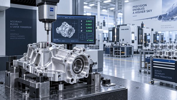
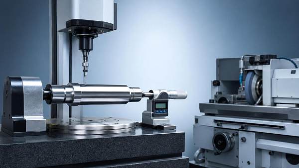
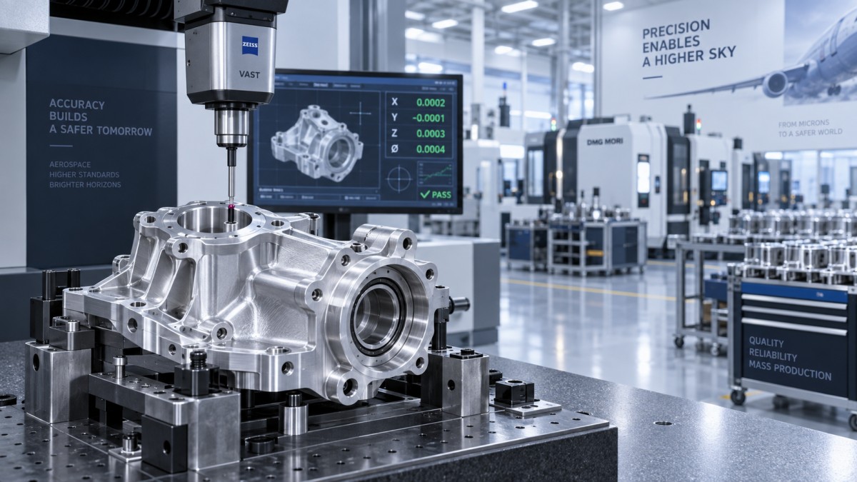
Measurement system analysis should be proportionate to the risk of the characteristic. For a simple external diameter, a calibrated micrometer and controlled technique may be adequate. For a freeform profile, a tight positional requirement, or a feature influenced by multiple datums, the measurement plan may require a coordinate measuring machine, a specialized fixture, programmed probing, validated software, and documented operator methods.
Calibration alone does not establish that an inspection method is capable. A calibrated instrument may still be unsuitable because its resolution is too coarse, its contact method deforms the part, its stylus cannot access the functional surface, or its result varies materially between operators and setups. Repeatability, reproducibility, bias, stability, environmental influence, and fixture variation all affect the confidence that can be placed in the result.
This matters most near tolerance limits. If the uncertainty associated with measurement is large relative to the tolerance band, a pass/fail decision may be unreliable. Teams should define a decision rule that addresses uncertainty rather than silently accepting every observed value inside the nominal limits. The applicable customer, regulatory, or quality-management requirement may prescribe how this must be handled; where it does not, the rule should still be established before production release and applied consistently.
Inspection programs also need change control. A CMM routine that passes a first article can later yield different results after a probe change, fixture modification, software update, altered alignment strategy, or revised datum construction. Critical programs should therefore be reviewed as controlled inspection methods, not treated as permanent simply because they are automated.
Separate Process Capability From Sample Conformance
A handful of acceptable parts proves only that acceptable parts were made under those particular conditions. It does not prove that the process is capable of remaining within tolerance when tools wear, machines warm up, material properties shift, or a new setup is introduced.
For release purposes, the process review should focus on the source of variation for each critical characteristic. Diameter variation may be driven by tool wear and thermal drift. Flatness may be affected by clamping force and residual stress. Position can shift with fixture location, work offset changes, or burrs on datum surfaces. A bore that is stable after machining may change after heat treatment, surface finishing, or cleaning. The inspection plan should reflect the point in the route where the requirement is functionally final.
Capability indices can help compare process spread and centering against specification limits, but they should not be used as a substitute for engineering judgment. An index calculated from a short, stable-looking run may conceal a setup-to-setup shift. A process can also show favorable statistical output while producing a functionally weak assembly if the tolerance allocation or datum interpretation is incorrect.
Production validation should therefore include conditions that resemble normal manufacturing rather than a tightly supervised demonstration run. The review should consider representative material, intended machine and fixture, expected tooling, normal setup procedures, qualified operators where applicable, and planned finishing or secondary operations. When a feature is highly sensitive to a later operation, validating it only at the machining center is incomplete.
For critical dimensions, the release file should make clear which evidence supports process control: first-article results, initial production data, capability study output where used, setup approval records, gauge validation, fixture approval, and containment actions for any observed instability. The objective is not to accumulate paperwork. It is to make the control logic visible enough that a later shift in process behavior can be recognized and investigated.
Use Tolerance Stack Analysis to Test the Assembly, Not Just the Component
Individual dimensions can be fully conforming while the assembled product fails. This is common when several components contribute to a clearance, alignment, preload, engagement length, or sensor gap. The component drawing may be correct, the inspection report may be correct, and the assembly may still have insufficient margin.
Tolerance stack analysis should be revisited before production release when a critical function depends on multiple manufactured features. The calculation must use the actual assembly relationship, including datum transfer, component movement, mating conditions, fastener effects, compliant features, and applicable geometric tolerances. A simple worst-case arithmetic stack can be appropriate for some safety-critical interfaces, but it may be overly conservative for independent and statistically distributed variation. Statistical methods can be useful when their assumptions are justified and when the resulting residual risk is acceptable to the product owner.
Quality personnel do not need to own the design analysis, but they should be able to challenge whether the validation evidence represents the functional condition. A report showing that each component passed inspection is not equivalent to proof that the assembly has adequate clearance or alignment at the limiting combinations of part variation.
Where direct assembly verification is practical, it can provide an important check on the analysis. Functional gauges may also be effective when they accurately represent the intended mating condition. However, a functional gauge must itself be controlled: its wear limits, calibration method, datum simulation, and acceptance logic need the same discipline applied to other inspection equipment.
Build an Acceptance Plan That Includes a Response to Failure
A production release package is incomplete when it identifies what will be measured but not what happens when the result trends toward failure. Quality plans should define the inspection frequency, sample basis, responsible role, record format, and escalation path for each critical characteristic. The response plan should be specific enough to prevent informal decisions during a time-sensitive production issue.
Useful controls may include first-piece verification after setup, defined checks after tool changes, in-process gauging, periodic CMM confirmation, automated offset correction under controlled rules, and segregated hold procedures. The right combination depends on the process and feature risk. A close-tolerance bore produced on a stable, monitored operation may need a different control strategy from a positional relationship created across multiple setups.
When a nonconformity occurs, the immediate question is not merely whether the measured value can be reworked into limits. The team should determine whether the failure indicates a broader loss of control. Review the inspection method, lot boundaries, last known acceptable condition, tool state, fixture integrity, machine offsets, material condition, and downstream processes before authorizing release of nearby product.
Any deviation from drawing requirements needs formal engineering disposition through the organization’s approved quality process. Repeated use of informal concessions is a warning sign that the specification, process, or measurement method has not been adequately resolved. For safety-relevant features, deviation review should also consider whether the original functional analysis remains valid.
What a Defensible Release Decision Looks Like
A defensible release decision does not require every dimension to have the same level of analysis. It requires the level of evidence to match the consequence of variation. Low-risk cosmetic dimensions may be managed through routine inspection. Features governing load transfer, pressure containment, alignment, medical-device function, aerospace performance, or safe operation warrant stronger links between drawing requirement, measurement method, process capability, and reaction plan.
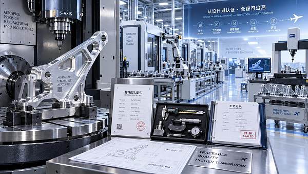
Before approving production, quality and safety teams should be able to trace each critical dimension from the functional requirement to a controlled drawing callout, a repeatable inspection method, evidence of process performance, and a documented action if control is lost. When any one of those links is weak, the part may still be machinable, but it has not yet been fully validated for release.
That distinction prevents a common and expensive mistake: confusing a successful inspection event with a controlled manufacturing process.
Search News
Hot Articles
- Carbon Fiber StructuresHow to Specify Aerospace Carbon Fiber Assemblies for Lightweight, Load-Bearing PartsJul 11, 2026
- Machine VisionXiaomi, Alibaba DAMO Academy Drive Open-Source Robotics Model Ecosystem, Lowering Algorithm Development Barriers for Overseas SMEs Adopting Chinese Robotics SolutionsMar 30, 2026
- Cobots & ArmsShanxi 'AI+' Conference Showcases Embodied Intelligence with Multinational Buyer Engagement: Key Industry ImplicationsMar 30, 2026
Popular Tags
Recommended News
 Jul 11, 2026How to Specify Aerospace Carbon Fiber Assemblies for Lightweight, Load-Bearing PartsAerospace carbon fiber assemblies: learn how to specify laminate design, load data, joining methods, and inspection controls for lighter, reliable load-bearing aerospace parts.Elena Rostova (UAV Systems Researcher)
 Mar 30, 2026Xiaomi, Alibaba DAMO Academy Drive Open-Source Robotics Model Ecosystem, Lowering Algorithm Development Barriers for Overseas SMEs Adopting Chinese Robotics SolutionsXiaomi & Alibaba DAMO Academy's open-source robotics models lower algorithm barriers for global SMEs. Boost efficiency in manufacturing, logistics & smart retail with ROS 2 compatible solutions.TSV Data Lab
 Mar 30, 2026Shanxi 'AI+' Conference Showcases Embodied Intelligence with Multinational Buyer Engagement: Key Industry ImplicationsShanxi 'AI+' Conference highlights embodied intelligence with Tesla, Ubtech & Jiantao showcasing multimodal robotics. 40+ global buyers validated tech on-site, creating new B2B channels for industrial automation & AI solutions.Chen Wei (Automation Lead Engineer)
 Mar 30, 2026Zhongguancun Unveils 6G Integrated Sensing-Computing-Intelligence Platform to Empower Embodied Robots for Global Industrial ApplicationsZhongguancun's new 6G platform revolutionizes industrial robotics with <10ms latency, empowering global automotive, logistics & port automation. Discover how this tech boosts China's smart manufacturing exports.TSV Data Lab
 Mar 30, 2026Mech-Mind Tianjin Embodied Intelligence R&D and Production Base Goes Live, Cutting Delivery Time by 20%–30% for Global Customized AMR+Vision SolutionsMech-Mind's Tianjin AMR+Vision production base cuts delivery time by 20%-30% for欧美 & Latin American markets. Discover how this PLd-certified facility accelerates customized robotics solutions for smart manufacturing and logistics.Chen Wei (Automation Lead Engineer)
 Mar 30, 2026Boao Forum Reveals 'Co-evolution of Big and Small Brains' Trend in Humanoid Robots, China's Embodied Intelligence Accelerates Adaptation to Overseas Manufacturing Service ScenariosDiscover how China's humanoid robots, featuring 'Co-evolution of Big and Small Brains,' are revolutionizing global manufacturing. Learn about Embodied Tian Gong 3.0's ISO compliance and overseas deployment at Boao Forum 2026.Chen Wei (Automation Lead Engineer)
 Mar 30, 2026China Railway Industrial Secures Patent for Embodied Robotics in Material Handling, Boosting High-Precision Delivery Capabilities for Overseas Infrastructure and Manufacturing ProjectsChina Railway Industrial's new patent for embodied robotics in material handling boosts high-precision delivery for global infrastructure & manufacturing. Discover how this innovation enhances logistics accuracy in automotive, rail transit & EPC projects.Chen Wei (Automation Lead Engineer)
 Sep 16, 2026Machining Tolerance Validation: How to Verify Critical Dimensions Before Production ReleaseMachining tolerance analysis validation: verify critical dimensions, measurement systems, process capability, and tolerance stacks before production release.Dr. Marcus Vance
 Sep 15, 2026AGV Tape Guidance vs Laser Navigation: Which Fits Your Warehouse Layout?AGV tape guidance comparison: discover how tape and laser navigation fit changing warehouse layouts, docking needs, floor conditions, maintenance, and route flexibility.Chen Wei (Automation Lead Engineer)
 Sep 14, 2026How Point Cloud Analytics Improves Asset Inspection Workflows Across GCC ProjectsPoint cloud analytics GCC helps project leaders improve asset inspections with accurate change detection, safer workflows, and faster maintenance decisions.TSV Data Lab
 Sep 13, 2026How Aerospace Manufacturers Can Build a Digital Thread From Design to Certified ProductionDigital manufacturing for aerospace: learn how to build a traceable digital thread from design through certified production, supplier control, and audit-ready compliance.Victor Lin (Chief Software Architect)
 Sep 12, 2026How to Select a Thermal Sensor for Mapping Drones in Surveying ProjectsMapping drone thermal sensor selection made simple: compare GSD, radiometric data, NETD, calibration, and workflow fit for accurate, survey-ready thermal maps.Elena Rostova (UAV Systems Researcher)
 Sep 11, 2026Integrating Photogrammetry Workflows into Digital Twin Projects Without Data BottlenecksPhotogrammetry workflow integration for digital twins: learn how to streamline capture, validation, versioning, and delivery to prevent data bottlenecks.Victor Lin (Chief Software Architect)
 Sep 10, 2026Hard-Tech Supply Chain Procurement: Qualifying Suppliers to Cut Lead-Time RiskHard-tech supply chain procurement guide: qualify suppliers with proven process, traceability, capacity, and change control to reduce lead-time risk.Chen Wei (Automation Lead Engineer)
 Sep 09, 2026Industrial Application Notes: Cost Factors That Shape Automation Project BudgetsIndustrial application notes cost factors explained: uncover the engineering, safety, integration, and commissioning variables that shape accurate automation budgets.Victor Lin (Chief Software Architect)
 Sep 08, 2026Supplier Discovery for Sourcing: How Buyers Can Verify Capability and Supply RiskSupplier discovery for sourcing: learn how to verify supplier capability, traceability, quote assumptions, and supply risk before placing production orders.TSV Data Lab
 Sep 07, 2026What Determines Process Control Systems Pricing? A Buyer’s Cost GuideProcess control systems pricing explained: compare hardware, engineering, integration, cybersecurity, validation, and lifecycle costs to choose the right-value solution.Victor Lin (Chief Software Architect)
 Sep 07, 2026AMR Robots in ASEAN: Which Industries Are Adopting Them—and Why?AMR robots ASEAN adoption is accelerating in electronics, automotive, warehousing, healthcare, and cold chain. Explore use cases, risks, and deployment insights.Chen Wei (Automation Lead Engineer)
 Sep 05, 2026How to Evaluate Supplier Qualification Support Tools for Industrial Procurement TeamsSupplier qualification support tools help industrial procurement teams verify technical evidence, manage risk, and make defensible supplier approvals. Learn what to evaluate.Victor Lin (Chief Software Architect)
 Sep 04, 2026Grinding Tolerance Analysis: How to Set Realistic Limits for Precision PartsGrinding tolerance analysis explains how to set realistic limits for precision parts, balance fit, geometry, process capability, and inspection for reliable performance.Dr. Marcus Vance
 Sep 03, 2026Warehouse Automation Strategies to Increase Storage Capacity Without ExpansionWarehouse automation space saving strategies help unlock vertical capacity, optimize slotting, and improve storage density without costly building expansion.Victor Lin (Chief Software Architect)
 Sep 02, 2026What Should Buyers Evaluate When Choosing a Hybrid VTOL UAV Factory?Hybrid VTOL UAV factory selection guide: evaluate mission fit, production traceability, payload integration, support, and total ownership costs before procurement.Elena Rostova (UAV Systems Researcher)
 Sep 01, 2026Cobot Collision Detection Settings: How to Tune Sensitivity, Force, and Stop LimitsCobot collision detection settings explained: tune sensitivity, force thresholds, payload data, and stop limits to reduce false trips and improve safer, reliable automation.Chen Wei (Automation Lead Engineer)
 Aug 31, 2026How Procurement Teams Can Measure and Reduce Supplier Discovery CostsSupplier discovery cost can drain time and budgets. Learn proven ways to measure hidden expenses, qualify suppliers faster, and reduce sourcing risk.Chen Wei (Automation Lead Engineer)