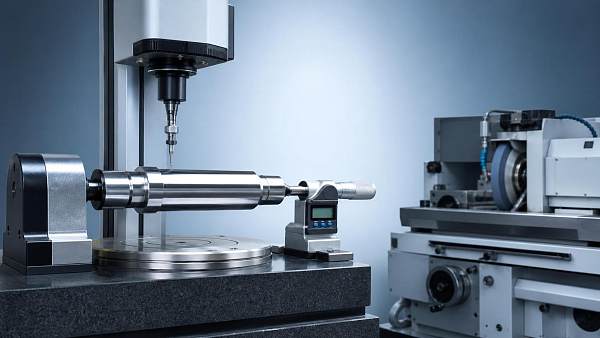
Custom Machining for Robotics Joints: Key Design Features That Affect Precision and Wear
Publication Date
author
Why joint machining decisions change once the robot leaves the CAD model
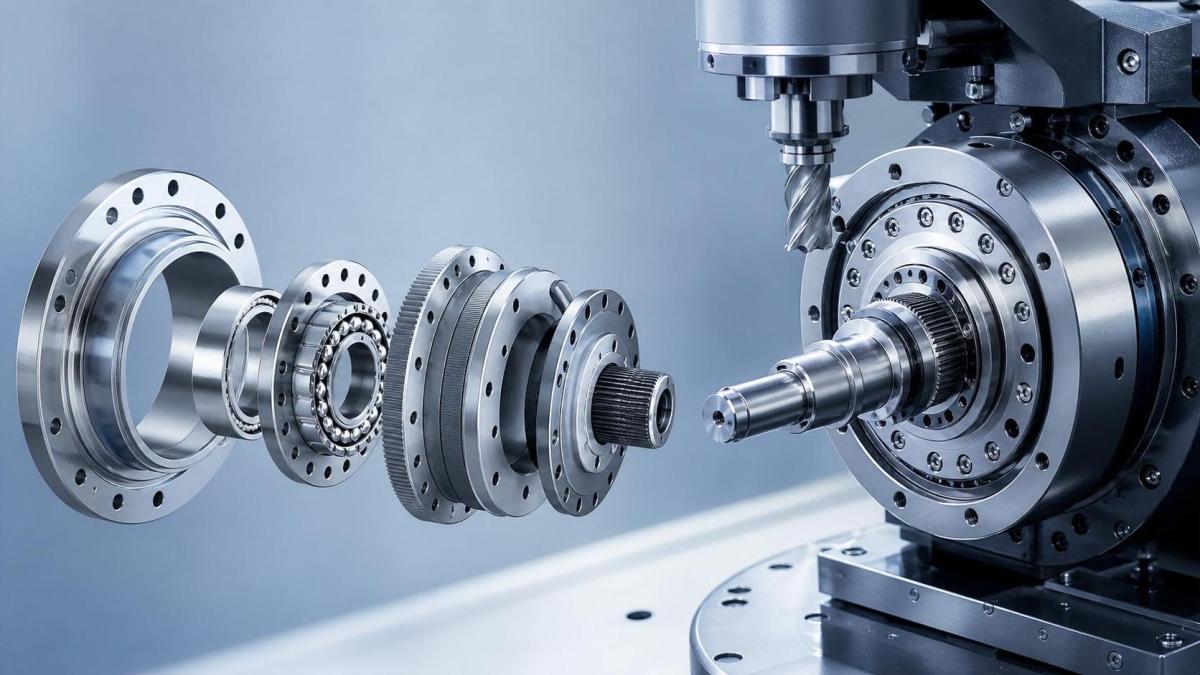
In robotics, joint precision is rarely decided by one dimension alone.
What matters is how custom machining for robotics joints behaves under load, heat, vibration, and repeated reversal.
A joint that looks acceptable in inspection can still generate backlash growth, uneven wear, or encoder drift after months of cycling.
That is why serious evaluation starts with the real application, not a generic tolerance claim.
TechStat Vanguard approaches this topic from a simple position: parameters must survive operating conditions, because tolerances dictate success only when they remain stable in service.
For custom machining for robotics joints, the useful questions are practical.
How concentric are the bearing seats after heat treatment? How consistent is surface finish across contact zones? How quickly does preload change under shock loading?
These details affect repeatability, service intervals, and total ownership cost more than polished marketing language ever will.
Different robotic duties create very different joint priorities
Not every robot joint fails for the same reason.
A collaborative arm handling light assembly often fights for smooth motion, low noise, and tight positional repeatability during frequent starts and stops.
A welding arm or palletizing unit usually sees higher moment loads, larger thermal swings, and longer duty cycles.
Mobile platforms and autonomous systems add another variable: constant micro-shock from travel, uneven floors, and contamination exposure.
Because of that, custom machining for robotics joints must be judged in context.
In a high-speed pick-and-place axis, inertia reversal can punish bore alignment more than peak static load.
In a UAV gimbal or compact inspection robot, weight reduction may matter, but stiffness loss cannot be ignored.
The common mistake is treating these applications as equivalent because they all use rotary joints.
They are not equivalent once wear mechanisms begin to diverge.
A practical comparison of where design focus shifts
This kind of comparison matters more than broad claims about precision machining capability.
When repeatability is the target, alignment and backlash come first
In servo-driven arms, repeatability problems often begin at the interfaces between shafts, housings, gear elements, and bearing seats.
Custom machining for robotics joints has to control coaxiality, perpendicularity, and fit consistency as a system, not as isolated features.
A small error stack across these interfaces can appear as lost motion at the tool center point.
In actual deployment, harmonic drive housings and crossed-roller bearing locations are especially sensitive.
If the mounting face is flat but not stable after stress release, measured precision may not survive assembly torque.
If a shaft seat reaches nominal size but surface waviness is inconsistent, preload can vary around the rotation.
That variation often shows up later as torque ripple, vibration, and non-linear wear.
For applications centered on path accuracy, it is usually wiser to request inspection data on runout, geometric position, and post-treatment stability.
Nominal tolerance alone says very little about long-term repeatability.
Heavy loads change the wear story more than many teams expect
Wear in high-load robotic joints is rarely caused by hardness alone.
More often, failure starts with imperfect load distribution.
Custom machining for robotics joints used in welding, machine tending, or lifting systems must maintain geometry under real clamping and dynamic force.
If housing stiffness is too low, the bearing race sees localized stress.
If shoulder transitions are poorly blended, stress concentration grows at exactly the point where fatigue life matters most.
Surface hardening can help, but only when supported by suitable core toughness and distortion control.
This is why machining route, material selection, and finishing method should be reviewed together.
A nitrided alloy steel joint may outperform a harder untreated component if the dimensional stability is better and the contact pattern is more even.
The more severe the duty cycle, the less useful it is to compare parts by hardness value alone.
What usually deserves closer attention in high-load joints
- Bearing seat roundness after heat treatment, not only before treatment.
- Transition radii near shoulders, splines, and flange roots.
- Surface finish direction where rolling or sliding contact occurs.
- Preload retention after shock, emergency stop, or overload events.
- Lubrication path geometry, especially in sealed compact joints.
Compact robots and lightweight axes need a different machining balance
Lightweight robotic systems create a different compromise.
Reducing mass improves speed and energy use, but it can reduce damping and structural margin.
In this setting, custom machining for robotics joints often involves thinner walls, smaller cross sections, and aggressive packaging around motors, encoders, and cable routing.
That makes machining distortion, burr control, and interface flatness more critical than expected.
A lightweight joint can meet static inspection targets and still develop poor wear behavior because local compliance changes the contact zone during acceleration.
This is common in compact cobots, small AMRs, and airborne robotic modules.
In such cases, the better question is not simply whether the part is light.
The better question is whether the machined geometry preserves stiffness where the bearing, reducer, and sensor references must stay aligned.
If that relationship drifts, precision decays quickly even without visible damage.
Surface integrity often decides whether wear stays predictable
Surface finish is not just a cosmetic item on a drawing.
For custom machining for robotics joints, surface integrity influences friction, lubrication film behavior, fretting resistance, and crack initiation.
A polished value on paper can still hide smeared material, residual tensile stress, or torn grain at the contact zone.
That is why finish method matters.
Grinding, honing, superfinishing, and controlled deburring do not create the same service behavior.
In clean environments, a poor edge condition may release particles and degrade motion quality.
In contaminated environments, roughness valleys can trap debris and accelerate abrasion.
TSV-style benchmarking is useful here because it pushes attention toward measurable outcomes.
Instead of asking whether the part is premium, ask how the chosen finish performs after defined cycle counts, load cases, and lubrication intervals.
Where teams often misread the real risk
Several errors appear again and again when specifying custom machining for robotics joints.
- Treating catalog tolerances as proof of assembled joint accuracy.
- Comparing machining quotes without checking process capability after heat treatment.
- Optimizing unit price while ignoring replacement labor, downtime, and recalibration cost.
- Assuming similar robots share the same wear pattern despite different motion profiles.
- Overlooking environmental exposure, especially coolant mist, dust, or outdoor corrosion.
The deeper issue is that many decisions are made from isolated parameters.
Joint machining quality should be read as a chain.
Material, process route, geometry retention, assembly condition, and operating load all influence precision and wear together.
A better way to judge custom machining for robotics joints before release
A useful evaluation method starts by mapping the joint to its operating pattern.
Define cycle rate, reversal frequency, peak and sustained load, shock events, temperature band, contamination risk, and maintenance interval.
Then match those conditions to the machining features that actually control failure risk.
This framework fits TSV’s broader view of industrial benchmarking.
Good sourcing and good engineering both improve when decisions are tied to verifiable data rather than broad capability claims.
The next useful step is to define the joint by service reality
Custom machining for robotics joints works best when the specification reflects how the joint will actually live.
That means separating high-cycle precision axes from shock-loaded axes, lightweight modules from heavy-duty housings, and clean environments from contaminated ones.
It also means documenting the parameters that influence wear growth, not just first-pass dimensional acceptance.
A practical next move is to build a short decision sheet for each joint.
List operating loads, alignment-critical interfaces, material and treatment assumptions, surface requirements, and the validation conditions needed before release.
When custom machining for robotics joints is evaluated this way, precision and wear become measurable engineering outcomes rather than optimistic expectations.
Search News
Hot Articles
- Carbon Fiber StructuresHow to Specify Aerospace Carbon Fiber Assemblies for Lightweight, Load-Bearing PartsJul 11, 2026
- Machine VisionXiaomi, Alibaba DAMO Academy Drive Open-Source Robotics Model Ecosystem, Lowering Algorithm Development Barriers for Overseas SMEs Adopting Chinese Robotics SolutionsMar 30, 2026
- Cobots & ArmsShanxi 'AI+' Conference Showcases Embodied Intelligence with Multinational Buyer Engagement: Key Industry ImplicationsMar 30, 2026
Popular Tags
Recommended News
 Jul 11, 2026How to Specify Aerospace Carbon Fiber Assemblies for Lightweight, Load-Bearing PartsAerospace carbon fiber assemblies: learn how to specify laminate design, load data, joining methods, and inspection controls for lighter, reliable load-bearing aerospace parts.Elena Rostova (UAV Systems Researcher)
 Mar 30, 2026Xiaomi, Alibaba DAMO Academy Drive Open-Source Robotics Model Ecosystem, Lowering Algorithm Development Barriers for Overseas SMEs Adopting Chinese Robotics SolutionsXiaomi & Alibaba DAMO Academy's open-source robotics models lower algorithm barriers for global SMEs. Boost efficiency in manufacturing, logistics & smart retail with ROS 2 compatible solutions.TSV Data Lab
 Mar 30, 2026Shanxi 'AI+' Conference Showcases Embodied Intelligence with Multinational Buyer Engagement: Key Industry ImplicationsShanxi 'AI+' Conference highlights embodied intelligence with Tesla, Ubtech & Jiantao showcasing multimodal robotics. 40+ global buyers validated tech on-site, creating new B2B channels for industrial automation & AI solutions.Chen Wei (Automation Lead Engineer)
 Mar 30, 2026Zhongguancun Unveils 6G Integrated Sensing-Computing-Intelligence Platform to Empower Embodied Robots for Global Industrial ApplicationsZhongguancun's new 6G platform revolutionizes industrial robotics with <10ms latency, empowering global automotive, logistics & port automation. Discover how this tech boosts China's smart manufacturing exports.TSV Data Lab
 Mar 30, 2026Mech-Mind Tianjin Embodied Intelligence R&D and Production Base Goes Live, Cutting Delivery Time by 20%–30% for Global Customized AMR+Vision SolutionsMech-Mind's Tianjin AMR+Vision production base cuts delivery time by 20%-30% for欧美 & Latin American markets. Discover how this PLd-certified facility accelerates customized robotics solutions for smart manufacturing and logistics.Chen Wei (Automation Lead Engineer)
 Mar 30, 2026Boao Forum Reveals 'Co-evolution of Big and Small Brains' Trend in Humanoid Robots, China's Embodied Intelligence Accelerates Adaptation to Overseas Manufacturing Service ScenariosDiscover how China's humanoid robots, featuring 'Co-evolution of Big and Small Brains,' are revolutionizing global manufacturing. Learn about Embodied Tian Gong 3.0's ISO compliance and overseas deployment at Boao Forum 2026.Chen Wei (Automation Lead Engineer)
 Mar 30, 2026China Railway Industrial Secures Patent for Embodied Robotics in Material Handling, Boosting High-Precision Delivery Capabilities for Overseas Infrastructure and Manufacturing ProjectsChina Railway Industrial's new patent for embodied robotics in material handling boosts high-precision delivery for global infrastructure & manufacturing. Discover how this innovation enhances logistics accuracy in automotive, rail transit & EPC projects.Chen Wei (Automation Lead Engineer)
 Sep 18, 2026Selecting UAV Aerospace Structural Parts for Strength, Weight, and Fatigue LifeUAV aerospace structural parts guide: compare strength, weight, stiffness, fatigue life, joints, and traceability to select reliable flight-ready components.Elena Rostova (UAV Systems Researcher)
 Sep 17, 2026Selecting Commercial Drone Payloads for European Inspection ProjectsCommercial drone payloads Europe: learn how to select RGB, thermal and LiDAR systems for compliant, reliable inspection data and better project outcomes.Elena Rostova (UAV Systems Researcher)
 Sep 16, 2026Machining Tolerance Validation: How to Verify Critical Dimensions Before Production ReleaseMachining tolerance analysis validation: verify critical dimensions, measurement systems, process capability, and tolerance stacks before production release.Dr. Marcus Vance
 Sep 15, 2026AGV Tape Guidance vs Laser Navigation: Which Fits Your Warehouse Layout?AGV tape guidance comparison: discover how tape and laser navigation fit changing warehouse layouts, docking needs, floor conditions, maintenance, and route flexibility.Chen Wei (Automation Lead Engineer)
 Sep 14, 2026How Point Cloud Analytics Improves Asset Inspection Workflows Across GCC ProjectsPoint cloud analytics GCC helps project leaders improve asset inspections with accurate change detection, safer workflows, and faster maintenance decisions.TSV Data Lab
 Sep 13, 2026How Aerospace Manufacturers Can Build a Digital Thread From Design to Certified ProductionDigital manufacturing for aerospace: learn how to build a traceable digital thread from design through certified production, supplier control, and audit-ready compliance.Victor Lin (Chief Software Architect)
 Sep 12, 2026How to Select a Thermal Sensor for Mapping Drones in Surveying ProjectsMapping drone thermal sensor selection made simple: compare GSD, radiometric data, NETD, calibration, and workflow fit for accurate, survey-ready thermal maps.Elena Rostova (UAV Systems Researcher)
 Sep 11, 2026Integrating Photogrammetry Workflows into Digital Twin Projects Without Data BottlenecksPhotogrammetry workflow integration for digital twins: learn how to streamline capture, validation, versioning, and delivery to prevent data bottlenecks.Victor Lin (Chief Software Architect)
 Sep 10, 2026Hard-Tech Supply Chain Procurement: Qualifying Suppliers to Cut Lead-Time RiskHard-tech supply chain procurement guide: qualify suppliers with proven process, traceability, capacity, and change control to reduce lead-time risk.Chen Wei (Automation Lead Engineer)
 Sep 09, 2026Industrial Application Notes: Cost Factors That Shape Automation Project BudgetsIndustrial application notes cost factors explained: uncover the engineering, safety, integration, and commissioning variables that shape accurate automation budgets.Victor Lin (Chief Software Architect)
 Sep 08, 2026Supplier Discovery for Sourcing: How Buyers Can Verify Capability and Supply RiskSupplier discovery for sourcing: learn how to verify supplier capability, traceability, quote assumptions, and supply risk before placing production orders.TSV Data Lab
 Sep 07, 2026What Determines Process Control Systems Pricing? A Buyer’s Cost GuideProcess control systems pricing explained: compare hardware, engineering, integration, cybersecurity, validation, and lifecycle costs to choose the right-value solution.Victor Lin (Chief Software Architect)
 Sep 07, 2026AMR Robots in ASEAN: Which Industries Are Adopting Them—and Why?AMR robots ASEAN adoption is accelerating in electronics, automotive, warehousing, healthcare, and cold chain. Explore use cases, risks, and deployment insights.Chen Wei (Automation Lead Engineer)
 Sep 05, 2026How to Evaluate Supplier Qualification Support Tools for Industrial Procurement TeamsSupplier qualification support tools help industrial procurement teams verify technical evidence, manage risk, and make defensible supplier approvals. Learn what to evaluate.Victor Lin (Chief Software Architect)
 Sep 04, 2026Grinding Tolerance Analysis: How to Set Realistic Limits for Precision PartsGrinding tolerance analysis explains how to set realistic limits for precision parts, balance fit, geometry, process capability, and inspection for reliable performance.Dr. Marcus Vance
 Sep 03, 2026Warehouse Automation Strategies to Increase Storage Capacity Without ExpansionWarehouse automation space saving strategies help unlock vertical capacity, optimize slotting, and improve storage density without costly building expansion.Victor Lin (Chief Software Architect)
 Sep 02, 2026What Should Buyers Evaluate When Choosing a Hybrid VTOL UAV Factory?Hybrid VTOL UAV factory selection guide: evaluate mission fit, production traceability, payload integration, support, and total ownership costs before procurement.Elena Rostova (UAV Systems Researcher)