Cobot Collision Detection Settings: How to Tune Sensitivity, Force, and Stop Limits
Publication Date
author
A collaborative robot that stops during harmless contact may look safe, yet it can quietly erode cycle time and create inconsistent process behavior. The opposite condition is more serious: a robot may continue farther into a fixture, part, or person because its collision threshold is too high, its payload model is wrong, or the stopping response has been misunderstood. In both cases, the problem is rarely solved by moving one sensitivity slider.
Effective cobot collision detection settings begin with a simple rule: tune the robot around the actual contact hazard and the actual motion dynamics, not around a default value or an isolated demonstration. Sensitivity determines how readily abnormal external force is recognized; force thresholds define the estimated load that triggers a response; stop limits determine what the controller does after detection. These settings must be evaluated together with payload, center of gravity, tool geometry, speed, acceleration, path direction, and the risk-reduction measures designed for the cell.
Separate collision detection from protective safety functions
Many interfaces place force, torque, sensitivity, and stop-response parameters close together, which can make them appear interchangeable. They are not. Collision detection generally compares measured or estimated joint torque against the robot’s expected dynamic model. A deviation beyond a configured condition is treated as contact or interference. Its performance depends on model accuracy, controller filtering, the selected operating mode, and the robot manufacturer’s implementation.
A protective stop function, safety-rated force limitation, emergency stop circuit, safety scanner, guard interlock, or enabling device serves a different role. Some cobots support safety-rated limits and some collision functions may be part of a safety configuration, but that status cannot be assumed from a label such as “collision sensitivity.” Review the robot documentation, the safety function description, and the cell risk assessment before treating any parameter as a personnel-protection control.
This distinction matters during commissioning. A process engineer may use low-threshold collision detection to protect a delicate gripper or locate a part edge. That does not automatically establish acceptable operator protection. Conversely, a safety limit may be appropriate for a defined collaborative condition while still being too restrictive for a high-inertia process move. Each function needs a stated purpose.
Start with the contact scenario, not the numerical setting
Before opening the settings page, define what the robot must detect and what it is allowed to touch. “Detect collision” is too broad to produce a defensible configuration. A tray-loading task, screwdriving routine, polishing path, and machine-tending operation create different contact signatures.
- Unexpected fixture contact: usually rigid, fast-rising, and localized. The goal may be to prevent bending a tool or dislodging a part.
- Process contact: intentional contact during insertion, sanding, dispensing, or probing. Detection must distinguish expected force from an abnormal condition.
- Human contact: may be compliant, variable in location, and affected by robot posture, moving mass, tool shape, and speed.
- Tool or cable interference: can develop gradually and may not produce a sharp force spike until the cable is already under strain.
For every relevant scenario, document the collision direction, likely contact point, expected contact stiffness, commanded speed, and desired response. A lateral strike near the end of a long tool creates a different joint-torque pattern from an axial push directly into the tool centerline. The same threshold can therefore be prompt in one pose and late in another.
Why payload data determines whether sensitivity can be trusted
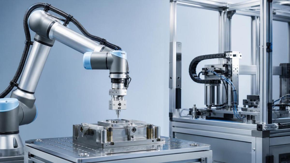
Collision algorithms need a prediction of normal robot effort. That prediction is only as good as the payload and center-of-gravity values configured in the controller. A gripper entered as a simple mass at the flange is not adequately modeled when the actual assembly has extended jaws, a vacuum manifold, fittings, and an offset workpiece.
An underestimated payload can make ordinary acceleration appear as an external disturbance, causing nuisance stops. An overestimated payload can mask real contact because the controller expects more torque than the robot actually needs. Errors become more visible during fast starts, abrupt direction reversals, vertical motion, and wrist rotation, where inertia and gravity effects vary strongly.
Validate the complete carried assembly rather than the empty tool. This includes adapters, sensors, cable dress, pneumatic lines where relevant, fasteners, and the maximum workpiece mass expected in the program. Confirm the center of gravity in all three axes. Where the robot supports multiple payload definitions, assign the correct one before a tool change or pick sequence instead of retaining a conservative “largest payload” model for every operation.
Payload accuracy does not eliminate false trips. Mechanical friction, temperature effects, gearbox behavior, external cable forces, and controller filtering can also influence detection. It does, however, remove one of the most common reasons a collision setting appears inconsistent across paths.
Set sensitivity and force limits as a paired decision
Interfaces vary. One robot may offer a sensitivity scale, while another exposes force and torque thresholds for each axis or Cartesian direction. Some systems use a percentage relative to internal limits, and others provide separate settings for free drive, program execution, or safety functions. Never transfer a numerical value between robot brands or even between different controller generations without understanding the underlying definition.
In practical terms, higher sensitivity usually means smaller deviations are recognized sooner. A lower force threshold similarly produces earlier detection. Both choices can reduce the amount of unintended travel after initial contact, but both also raise the chance that normal process forces, acceleration transients, or vibration trigger a stop.
A good starting strategy is to test the smallest credible abnormal contact that must be detected, under slow and controlled conditions. Establish whether the controller recognizes it consistently in the relevant approach direction. Then introduce normal operating speed and acceleration in steps. This reveals whether the setting is limited by process dynamics rather than contact force alone.
Do not compensate for nuisance trips by globally reducing sensitivity until the robot “runs without stopping.” That approach often hides a payload-model error or a path problem. It can also make a later change in tooling, part mass, or speed much harder to diagnose because the baseline was never established.
Stop limits must account for motion after detection
Detection is not the same as stopping at the instant of contact. Between the first detectable deviation and full standstill, the robot may continue moving. The distance and energy involved depend on controller cycle time, filtering, brake behavior, robot speed, joint configuration, payload inertia, gravity direction, and the stop category selected by the system.
This is why a collision setting that appears acceptable at a teaching speed can be unsuitable during production motion. A long-reach posture carrying an offset load can have considerably more effective inertia than a compact posture holding the same mass close to the flange. Likewise, the fastest axis is not always the greatest hazard; a slower wrist rotation can trap or scrape when a long tool sweeps near an obstruction.
Define the permitted residual motion after contact. For fixture protection, the concern may be whether the tool can move far enough after detection to damage a locating pin. For a human-contact assessment, the concern is broader: contact location, possible trapping points, tool geometry, pressure, transient and quasi-static behavior, and the collaborative operation design all matter. Do not use an informal hand-push test as proof that a production-speed configuration is acceptable.
Use different profiles when the task genuinely changes
A single global setting is attractive because it is easy to maintain, but it often forces a poor compromise. An approach move through open space may need higher speed and a detection configuration that tolerates normal dynamic loads. The final insertion move may need a lower speed, smaller threshold, and a limited travel window. A screwdriving or dispensing sequence may require intentional force control, with separate abnormal-force boundaries outside the expected process band.
Where the controller permits it, create named, controlled parameter sets tied to defined program states: empty gripper travel, loaded part travel, approach to a fixture, contact process, and retreat. The names should describe the operating condition rather than vague labels such as “soft” or “high.” Record the active payload, speed cap, collision threshold or sensitivity, intended stop response, and reason for the selection.
Profile changes need protection against programming mistakes. Ensure transitions occur before the robot enters the relevant zone, restore the correct settings after a process step, and include them in program review. A collision profile intended for a slow insertion should not remain active during a high-speed transfer, and a transfer profile should not be carried into a contact-sensitive operation.
A commissioning sequence that produces usable evidence
Testing should progress from model validation to controlled contact, then to production-like motion. Start with the cell in a condition that allows safe observation and recovery. Confirm that fixtures, tool mounting, cable routing, and end-of-arm hardware are mechanically sound; a loose component can create misleading collision signatures.
- Load the correct tool and workpiece payload data, including center of gravity and any available inertia information.
- Run the intended path without contact at reduced speed. Look for torque deviations, vibration, cable pull, or unexpected stops near singularities and abrupt corners.
- Check the response to a controlled, non-destructive contact in the actual working pose and direction. Use a method appropriate to the equipment and cell safety plan.
- Increase speed and acceleration gradually while repeating only the tests needed to verify the response remains predictable.
- Verify recovery behavior: whether the robot holds position, releases drive power, requires acknowledgment, retracts only under a defined procedure, or needs fault clearing.
- Document the final values with the program version, tool configuration, and operating assumptions.
Record false stops as carefully as missed detections. A stop during a particular wrist rotation or at one corner of a path is valuable diagnostic information. It may point to a sharp acceleration change, an inaccurate center of gravity, a cable snag, or resonance in the tooling—not necessarily a need for a higher threshold.
Do not overlook the end effector and the environment
Collision performance is affected by what the robot carries. A soft vacuum cup may compress and spread contact over time, while a narrow metal probe can concentrate force rapidly. A spring-loaded tool can absorb initial contact and delay the force seen by the robot joints. An external force-torque sensor can provide more direct process feedback, but it also requires correct calibration, filtering, overload management, and a clear decision about which controller function initiates the stop.
Fixtures deserve the same attention. Rigid stops produce distinct events; flexible guards, floating locators, loose bins, and stacked parts can create ambiguous signals. Where contact is unavoidable, redesigning the approach geometry, adding compliant guidance, reducing speed within the contact zone, or improving fixture clearances may be more reliable than forcing collision detection to solve a mechanical design problem.
When a setting should be revisited
Revalidate collision behavior after changing the gripper, adding a camera or sensor, altering cable routing, changing part mass, increasing speed, modifying a trajectory, or moving fixtures. A software update can also change available parameters, filtering behavior, or safety-function implementation. Treat the prior configuration as evidence for the prior cell state, not as a permanent answer.
Where settings contribute to personnel protection, release them only through the documented risk-assessment and validation process for the complete application. The meaningful question is not whether the cobot stops when pushed by hand; it is whether the configured robot, tool, trajectory, environment, and stop response control the defined hazards under the conditions in which the cell will actually run.
Search News
Hot Articles
- Carbon Fiber StructuresHow to Specify Aerospace Carbon Fiber Assemblies for Lightweight, Load-Bearing PartsJul 11, 2026
- Machine VisionXiaomi, Alibaba DAMO Academy Drive Open-Source Robotics Model Ecosystem, Lowering Algorithm Development Barriers for Overseas SMEs Adopting Chinese Robotics SolutionsMar 30, 2026
- Cobots & ArmsShanxi 'AI+' Conference Showcases Embodied Intelligence with Multinational Buyer Engagement: Key Industry ImplicationsMar 30, 2026
Popular Tags
Recommended News
 Jul 11, 2026How to Specify Aerospace Carbon Fiber Assemblies for Lightweight, Load-Bearing PartsAerospace carbon fiber assemblies: learn how to specify laminate design, load data, joining methods, and inspection controls for lighter, reliable load-bearing aerospace parts.Elena Rostova (UAV Systems Researcher)
 Mar 30, 2026Xiaomi, Alibaba DAMO Academy Drive Open-Source Robotics Model Ecosystem, Lowering Algorithm Development Barriers for Overseas SMEs Adopting Chinese Robotics SolutionsXiaomi & Alibaba DAMO Academy's open-source robotics models lower algorithm barriers for global SMEs. Boost efficiency in manufacturing, logistics & smart retail with ROS 2 compatible solutions.TSV Data Lab
 Mar 30, 2026Shanxi 'AI+' Conference Showcases Embodied Intelligence with Multinational Buyer Engagement: Key Industry ImplicationsShanxi 'AI+' Conference highlights embodied intelligence with Tesla, Ubtech & Jiantao showcasing multimodal robotics. 40+ global buyers validated tech on-site, creating new B2B channels for industrial automation & AI solutions.Chen Wei (Automation Lead Engineer)
 Mar 30, 2026Zhongguancun Unveils 6G Integrated Sensing-Computing-Intelligence Platform to Empower Embodied Robots for Global Industrial ApplicationsZhongguancun's new 6G platform revolutionizes industrial robotics with <10ms latency, empowering global automotive, logistics & port automation. Discover how this tech boosts China's smart manufacturing exports.TSV Data Lab
 Mar 30, 2026Mech-Mind Tianjin Embodied Intelligence R&D and Production Base Goes Live, Cutting Delivery Time by 20%–30% for Global Customized AMR+Vision SolutionsMech-Mind's Tianjin AMR+Vision production base cuts delivery time by 20%-30% for欧美 & Latin American markets. Discover how this PLd-certified facility accelerates customized robotics solutions for smart manufacturing and logistics.Chen Wei (Automation Lead Engineer)
 Mar 30, 2026Boao Forum Reveals 'Co-evolution of Big and Small Brains' Trend in Humanoid Robots, China's Embodied Intelligence Accelerates Adaptation to Overseas Manufacturing Service ScenariosDiscover how China's humanoid robots, featuring 'Co-evolution of Big and Small Brains,' are revolutionizing global manufacturing. Learn about Embodied Tian Gong 3.0's ISO compliance and overseas deployment at Boao Forum 2026.Chen Wei (Automation Lead Engineer)
 Mar 30, 2026China Railway Industrial Secures Patent for Embodied Robotics in Material Handling, Boosting High-Precision Delivery Capabilities for Overseas Infrastructure and Manufacturing ProjectsChina Railway Industrial's new patent for embodied robotics in material handling boosts high-precision delivery for global infrastructure & manufacturing. Discover how this innovation enhances logistics accuracy in automotive, rail transit & EPC projects.Chen Wei (Automation Lead Engineer)
 Oct 16, 2026Choosing a Rugged Edge AI Box Supplier: Thermal Tests and Lifecycle SupportChoose a rugged edge AI box supplier with proven thermal performance and reliable lifecycle support. Discover the tests and commitments to verify before you buy.TSV Data Lab
 Oct 15, 2026R&D Cost Reduction Services: How to Evaluate Fees, Savings, and ROIEvaluate R&D cost reduction services with confidence. Compare fees, verify savings, and calculate ROI without compromising performance. Discover how to choose a provider that delivers real value.Chen Wei (Automation Lead Engineer)
 Oct 15, 2026How Should You Compare TechStat Vanguard 5-Axis CNC Tolerances?TechStat Vanguard 5-axis CNC tolerance comparison: learn how to verify part accuracy, assess inspection evidence, and choose suppliers that reliably meet your drawing requirements.Dr. Marcus Vance
 Oct 14, 2026Drone Frame Composites: Carbon Fiber vs. Fiberglass for Weight and StiffnessExplore drone structural materials composites: compare carbon fiber and fiberglass for weight, stiffness, cost, and antenna compatibility. Find the right material for your drone frame.Elena Rostova (UAV Systems Researcher)
 Oct 13, 2026Smart Cameras vs. PC-Based Machine Vision: Which Fits High-Speed Inspection?This industrial product comparison for machine vision weighs smart cameras vs. PC-based systems on latency, throughput, and cost. Discover your best fit for high-speed inspection.TSV Data Lab
 Oct 12, 2026How to Verify RoHS Compliance in Industrial Sensing Systems Before DeploymentRoHS compliant sensing systems: learn how to verify materials, supplier declarations, testing, and configuration controls before industrial deployment.TSV Data Lab
 Oct 11, 2026How Procurement-Oriented Content Taxonomy Improves B2B Buying JourneysProcurement-oriented content taxonomy streamlines B2B buying journeys with clearer evidence, supplier comparisons, risk visibility, and faster approvals.TSV Data Lab
 Oct 10, 2026How to Select a Machine Performance Monitoring Platform for OEE and Downtime ReductionMachine performance monitoring platform selection guide: validate machine states, OEE data, downtime reasons, integrations, and scalability to reduce losses with confidence.TSV Data Lab
 Oct 08, 2026How to Machine Inconel 625 Blades Without Heat Cracks or Edge ChippingInconel 625 blade machining guide: prevent heat cracks, edge chipping, chatter, and work hardening with proven tooling, cooling, fixturing, and inspection strategies.Dr. Marcus Vance
 Oct 07, 2026How to Evaluate an HMI Panel Distributor for Industrial Automation ProjectsHMI panel distributor evaluation guide: verify technical compatibility, traceability, supply reliability, lifecycle support, and total cost for automation projects.Victor Lin (Chief Software Architect)
 Oct 06, 2026Navigation Fault Tolerance Standards for AMRs: What Safety Teams Must VerifyNavigation fault tolerance standards: learn what AMR safety teams must verify, from localization loss and sensor faults to stopping distance, safe restart, and site-specific validation.Chen Wei (Automation Lead Engineer)
 Oct 05, 2026Calculating Edge Computing Total Cost of Ownership Across Distributed SitesEdge computing ownership cost explained: calculate deployment, energy, connectivity, security, remote support, and refresh costs across distributed sites.TSV Data Lab
 Oct 04, 2026CAD/CAM Benchmarking in the GCC: What Manufacturers Should Ask a ConsultantCAD CAM benchmark consultant GCC guide: learn the key questions manufacturers should ask to validate post-processors, workflows, machine performance, and production risk.Victor Lin (Chief Software Architect)
 Oct 03, 2026Selecting Automotive Radar Sensor Modules for ADAS Range, Resolution, and IntegrationAutomotive radar sensor module selection guide for ADAS: compare range, resolution, field of view, latency, and integration to build safer, reliable vehicle systems.TSV Data Lab
 Oct 02, 2026How to Qualify Machined Parts Suppliers for Hard Tech ProgramsHard tech supply chain machined parts demand rigorous supplier qualification. Learn how to assess capability, traceability, quality controls, and delivery resilience.Dr. Marcus Vance
 Oct 01, 2026How to Select an Outdoor Security Radar Sensor for Perimeter Detection?Outdoor security radar sensor selection guide: compare range, accuracy, false-alarm control, integration, and field testing for reliable perimeter detection.TSV Data Lab
 Sep 30, 2026How to Evaluate Solid-State LiDAR Hardware for Outdoor Autonomous VehiclesSolid state LiDAR hardware evaluation guide for outdoor autonomous vehicles—compare range, point-cloud quality, environmental resilience, integration, and safety.TSV Data Lab