How to Read 5-Axis CNC Machining Fatigue Test Reports for Aerospace Part Approval
Publication Date
author
For aerospace part approval, reading 5-axis CNC machining fatigue test reports is less about checking compliance boxes and more about verifying structural truth. A report may show a passing result, yet still hide risk in load definition, machining influence, specimen preparation, or statistical weakness. In a market crowded with polished supplier claims, the real task is to connect fatigue data to flight conditions, manufacturing process control, and approval confidence.
Why these reports matter beyond a pass mark
Aerospace parts rarely fail because one number looked slightly low.
They fail when test evidence is interpreted without context.
That is why 5-axis CNC machining fatigue test reports carry weight in approval reviews.
They reveal how machining strategy, material condition, and cyclic stress interact over time.
For airframe brackets, engine-adjacent fixtures, UAV structures, and control housings, that interaction is decisive.
TechStat Vanguard frames this issue clearly: parameters matter more than slogans, and tolerances govern outcomes.
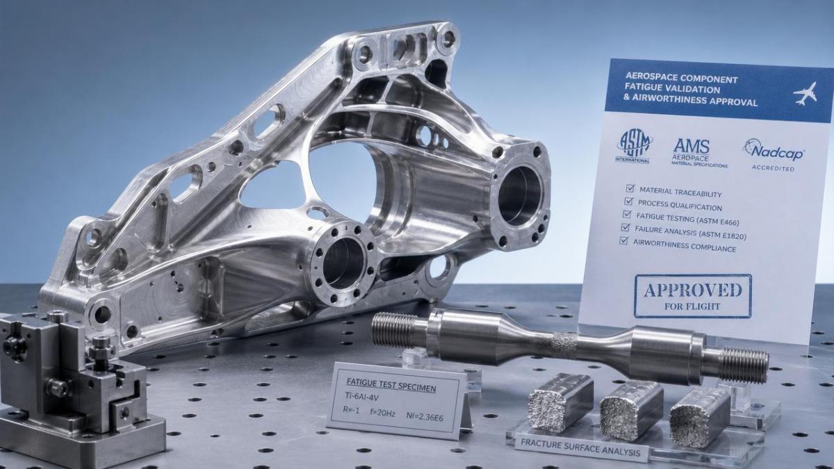
In practice, the report becomes a filter against information noise.
It helps separate a controlled aerospace process from a persuasive sales narrative.
What a fatigue report is really describing
A fatigue report is not only about endurance life.
It is a structured record of how a part or specimen behaves under repeated loading.
When 5-axis machining is involved, the report also reflects process fingerprints.
Toolpath direction, cutter engagement, surface finish, residual stress, and local heat input may all shape fatigue behavior.
That matters because aerospace geometry is rarely simple.
Complex curvature, thin walls, blended transitions, and difficult alloys often require 5-axis strategies that improve form but complicate fatigue interpretation.
A useful reading starts with one question: does the report represent the real manufacturing route and the real service load case?
Key report elements to locate first
- Material grade, heat treatment state, and lot traceability.
- Specimen geometry and whether it matches the critical design feature.
- Machining route, including tool orientation, finishing passes, and post-processing.
- Load ratio, frequency, stress level, and cycle count definition.
- Failure criterion, crack detection method, and acceptance threshold.
How to read the numbers with engineering discipline
The most common mistake is reading only the conclusion page.
A stronger approach is to move from boundary conditions to failure evidence.
Start with load definition
Check whether the cyclic load represents tensile, bending, torsional, or mixed-mode service conditions.
If the part sees multiaxial stress in service, a simple uniaxial fatigue result may understate risk.
Also verify the stress ratio, usually expressed as R.
A good life result at one R-value does not automatically transfer to another operating envelope.
Then examine cycles to initiation and final failure
Many 5-axis CNC machining fatigue test reports compress these stages into one outcome.
That can be misleading.
Early crack initiation often points to surface integrity problems.
Long crack propagation may instead reflect base material toughness and geometry sensitivity.
If initiation happens near tool marks, edge breaks, or blended corners, machining influence is likely significant.
Look for statistical depth
A single successful sample proves very little.
Useful fatigue evidence includes sample count, scatter band, confidence level, and any runout treatment.
Without that, the report may describe a favorable event rather than a dependable process.
Why 5-axis machining changes the reading
Not all fatigue reports deserve equal confidence.
For 5-axis parts, process complexity adds several hidden variables.
Tool access may improve geometry accuracy but alter local cutting direction.
Five-axis interpolation may reduce setups yet introduce subtle marks at transitions.
Thin sections may vibrate differently across orientations.
Specialty alloys can also respond sharply to temperature and chip load variations.
This is why Precision Machining Benchmarks, as emphasized by TSV, should be tied to actual process windows rather than generic capability claims.
When reading 5-axis CNC machining fatigue test reports, always ask whether the specimen came from the same setup logic used for production hardware.
Red flags that deserve a second look
- Specimens machined flat, while the approved part has compound curvature.
- No disclosure of final finishing, polishing, shot peening, or coating.
- Test frequency high enough to distort thermal response.
- Failure photos absent or too vague to locate crack origin.
- Results reported only as pass or fail, with no scatter discussion.
Where report interpretation affects real approval decisions
These reports influence more than one gate in the supply chain.
They shape first article acceptance, supplier comparison, deviation review, and ongoing process monitoring.
For UAV and aerospace programs, they also affect how conservatively design margins are applied.
A clean report can support confidence in a machining route.
A weak report can justify additional coupon testing, fractography, or process capability review before release.
That is especially relevant when switching suppliers, changing alloys, or moving from prototype to serial production.
In broader industrial terms, 5-axis CNC machining fatigue test reports function as a trust document.
They reduce trial-and-error costs only when they are read with enough technical discipline.
A practical review sequence for stronger decisions
A compact review routine often works better than a long checklist.
- Match the test article to the actual part geometry and machining route.
- Confirm the material state, traceability chain, and any thermal history.
- Compare load definitions with the real mission or service envelope.
- Review crack origin evidence before accepting any life claim.
- Check sample count and scatter before treating results as process capability.
- Flag gaps that require retest, added coupons, or stricter production controls.
This sequence keeps attention on evidence, not presentation quality.
It also aligns with TSV’s larger principle that engineering decisions should be built on verified parameters, not promotional language.
What to do after the report review
A fatigue report should lead to a clearer next step, not a vague impression.
If the evidence is strong, it can support approval with defined process controls.
If the evidence is partial, build a targeted follow-up around the missing variables.
That may include residual stress mapping, additional specimen orientations, surface integrity checks, or load-case refinement.
The most useful outcome is a documented internal standard for reading 5-axis CNC machining fatigue test reports.
Once that standard exists, supplier comparisons become more consistent, and aerospace part approval becomes less vulnerable to noise.
In the end, reliable approval depends on a simple discipline: follow the load, follow the crack, follow the process, and let the data speak.
Search News
Hot Articles
- Carbon Fiber StructuresHow to Specify Aerospace Carbon Fiber Assemblies for Lightweight, Load-Bearing PartsJul 11, 2026
- Machine VisionXiaomi, Alibaba DAMO Academy Drive Open-Source Robotics Model Ecosystem, Lowering Algorithm Development Barriers for Overseas SMEs Adopting Chinese Robotics SolutionsMar 30, 2026
- Cobots & ArmsShanxi 'AI+' Conference Showcases Embodied Intelligence with Multinational Buyer Engagement: Key Industry ImplicationsMar 30, 2026
Popular Tags
Recommended News
 Jul 11, 2026How to Specify Aerospace Carbon Fiber Assemblies for Lightweight, Load-Bearing PartsAerospace carbon fiber assemblies: learn how to specify laminate design, load data, joining methods, and inspection controls for lighter, reliable load-bearing aerospace parts.Elena Rostova (UAV Systems Researcher)
 Mar 30, 2026Xiaomi, Alibaba DAMO Academy Drive Open-Source Robotics Model Ecosystem, Lowering Algorithm Development Barriers for Overseas SMEs Adopting Chinese Robotics SolutionsXiaomi & Alibaba DAMO Academy's open-source robotics models lower algorithm barriers for global SMEs. Boost efficiency in manufacturing, logistics & smart retail with ROS 2 compatible solutions.TSV Data Lab
 Mar 30, 2026Shanxi 'AI+' Conference Showcases Embodied Intelligence with Multinational Buyer Engagement: Key Industry ImplicationsShanxi 'AI+' Conference highlights embodied intelligence with Tesla, Ubtech & Jiantao showcasing multimodal robotics. 40+ global buyers validated tech on-site, creating new B2B channels for industrial automation & AI solutions.Chen Wei (Automation Lead Engineer)
 Mar 30, 2026Zhongguancun Unveils 6G Integrated Sensing-Computing-Intelligence Platform to Empower Embodied Robots for Global Industrial ApplicationsZhongguancun's new 6G platform revolutionizes industrial robotics with <10ms latency, empowering global automotive, logistics & port automation. Discover how this tech boosts China's smart manufacturing exports.TSV Data Lab
 Mar 30, 2026Mech-Mind Tianjin Embodied Intelligence R&D and Production Base Goes Live, Cutting Delivery Time by 20%–30% for Global Customized AMR+Vision SolutionsMech-Mind's Tianjin AMR+Vision production base cuts delivery time by 20%-30% for欧美 & Latin American markets. Discover how this PLd-certified facility accelerates customized robotics solutions for smart manufacturing and logistics.Chen Wei (Automation Lead Engineer)
 Mar 30, 2026Boao Forum Reveals 'Co-evolution of Big and Small Brains' Trend in Humanoid Robots, China's Embodied Intelligence Accelerates Adaptation to Overseas Manufacturing Service ScenariosDiscover how China's humanoid robots, featuring 'Co-evolution of Big and Small Brains,' are revolutionizing global manufacturing. Learn about Embodied Tian Gong 3.0's ISO compliance and overseas deployment at Boao Forum 2026.Chen Wei (Automation Lead Engineer)
 Mar 30, 2026China Railway Industrial Secures Patent for Embodied Robotics in Material Handling, Boosting High-Precision Delivery Capabilities for Overseas Infrastructure and Manufacturing ProjectsChina Railway Industrial's new patent for embodied robotics in material handling boosts high-precision delivery for global infrastructure & manufacturing. Discover how this innovation enhances logistics accuracy in automotive, rail transit & EPC projects.Chen Wei (Automation Lead Engineer)
 Oct 27, 2026GXO and Agility Robotics Expand Partnership to Accelerate US Humanoid Robot DeploymentGXO and Agility Robotics plan to expand US humanoid robot deployment with Digit 4 in early 2027. Explore warehouse automation plans, service terms and future Digit 5 upgrades.Chen Wei (Automation Lead Engineer)
 Oct 27, 2026Robotic Automation Costs: Budgeting for Equipment, Integration, and MaintenancePlan your robotics automation cost with confidence. Explore equipment, integration, and maintenance expenses, compare quotes, and build a realistic budget for better ROI.Chen Wei (Automation Lead Engineer)
 Oct 26, 2026AMAXiMAL Releases Open-Source TopMod 3D v3 With Claude AIExplore AMAXiMAL’s free, open-source TopMod 3D v3 with Claude AI assistance, topology-based modeling and plywood fabrication tools that connect complex designs to physical builds.Dr. Marcus Vance
 Oct 26, 2026Choosing a SCADA System Integrator Company: PLC Compatibility and Long-Term SupportChoose a scada system integrator company with proven PLC compatibility and reliable long-term support. Discover what to test, compare, and require before investing.Victor Lin (Chief Software Architect)
 Oct 25, 2026Hesai Leads Global ADAS Main Lidar Shipments in Yole’s 2026 ReportHesai led global ADAS main lidar shipments with a 43% share in 2025, according to Yole’s 2026 report. Explore what this ranking reveals about its automotive market position.TSV Data Lab
 Oct 25, 2026Choosing an Aerospace Materials Manufacturer: Quality and Traceability ChecksChoosing an aerospace materials manufacturer? Learn how to verify certifications, test reports, and lot traceability to qualify suppliers confidently and reduce costly sourcing risks.Dr. Marcus Vance
 Oct 24, 2026Guotai Haitong: Global Entry-Level 3D Printer Shipments Rose 39% in Q1 2026Entry-level 3D printer shipments rose 39% in Q1 2026, Guotai Haitong reports. Explore how AI, multicolor printing and print farms are shaping market growth.Dr. Marcus Vance
 Oct 24, 2026Choosing an Industrial Vision Inspection Supplier: Acceptance Tests That MatterChoose an industrial vision inspection supplier with confidence. Discover acceptance tests for defect detection, false rejects, production speed, and reliable part rejection before you buy.TSV Data Lab
 Oct 23, 2026US Navy Raises Gecko Robotics Contract Ceiling to $300M for Robotic Fleet MaintenanceUS Navy raises Gecko Robotics’ contract ceiling to $300M for Pacific Fleet robotic inspections. Explore potential opportunities for maintenance suppliers and key procurement considerations.Chen Wei (Automation Lead Engineer)
 Oct 23, 2026Choosing Industrial Sensing Systems for Global Plants: Protocol CompatibilityCompare industrial sensing systems international buyers can trust. Explore protocol compatibility, reduce integration risks, and select proven configurations for reliable global plant deployments.TSV Data Lab
 Oct 22, 2026KUKA Showcases Physical AI and iiQKA.AI Vision at NVIDIA GTC BerlinExplore KUKA’s Physical AI showcase at NVIDIA GTC Berlin and discover how iiQKA.AI Vision aims to simplify robotic vision integration and improve 2D and 3D scene recognition.TSV Data Lab
 Oct 22, 2026Robotic Machining of Advanced Composites: What Tolerances Are Achievable?Explore advanced materials machining robotics: discover what drives achievable composite tolerances and how to validate accuracy before investing in your next machining system.Dr. Marcus Vance
 Oct 21, 2026China’s Industrial Robot Exports Near RMB 10 Billion in First Nine Months of 2026China’s industrial robot exports neared RMB 10 billion in January–September 2026, with value rising faster than volume. Explore the data and what it could mean for suppliers.Chen Wei (Automation Lead Engineer)
 Oct 21, 2026Low-Latency Industrial Data Processing: Pricing and Key Cost DriversExplore industrial data latency price drivers, from edge hardware to integration and support. Learn how to compare quotes, verify performance, and avoid unnecessary costs.TSV Data Lab
 Oct 20, 2026KUKA Launches iiQKA.AI Vision to Simplify Industrial Image ProcessingKUKA iiQKA.AI Vision simplifies industrial image processing with controller-based 2D and 3D vision. Explore drag-and-drop setup for vision-guided automation.TSV Data Lab
 Oct 20, 2026Smart Industrial Edge Devices: Key Criteria for Legacy PLC IntegrationChoose smart industrial edge devices for legacy PLC integration. Discover key criteria for compatibility, data quality, security, and reliable collection without disrupting control.TSV Data Lab
 Oct 19, 2026Choosing a Radar Sensor by Application: Range, Resolution, and Field of ViewSimplify radar sensor application based product selection. Compare range, resolution, and field of view to avoid blind spots and choose with confidence. Explore the guide.TSV Data Lab