Custom Machining for Robotics Joints: Tolerances, Materials, and Failure Risks
Publication Date
author
In high-performance robotics, joint reliability is defined long before assembly—at the machining stage. Custom machining for robotics joints directly shapes motion accuracy, load stability, service life, and failure exposure. For project leaders balancing performance, cost, and supplier risk, understanding tolerances, material trade-offs, and common failure modes is essential to making informed sourcing and engineering decisions.
In practical terms, the joint is where design intent meets manufacturing reality. A robot may have a strong controller, a premium gearbox, and a well-tuned servo, yet still miss repeatability targets if the housing bores drift by 15–25 µm, bearing fits are inconsistent, or shaft concentricity is not maintained across production batches.
For engineering managers and project owners, this makes custom machining for robotics joints more than a component sourcing topic. It is a risk-control discipline that affects commissioning time, field maintenance frequency, warranty exposure, and the long-term total cost of ownership.
Why Joint Machining Quality Determines Robot Performance
Robotics joints operate under combined loads rather than simple static conditions. In a 6-axis arm, one joint may simultaneously experience torsion, radial load, axial preload, vibration, thermal cycling, and acceleration spikes during stop-start motion. Even a small machining error can propagate through the kinematic chain and reduce end-effector accuracy.
This is especially important in collaborative robots, industrial manipulators, AGV steering modules, and UAV gimbal systems. In these applications, allowable backlash may be measured in arc-minutes, while dimensional variation in key bores or mating surfaces may need to stay within ±0.005 mm to ±0.02 mm depending on architecture, speed, and payload class.
Key Functional Areas Affected by Machining
- Bearing seats: influence preload stability, heat generation, and rotational smoothness.
- Gearbox interfaces: affect backlash, alignment, and torque transmission efficiency.
- Motor mounting faces: determine coaxiality and vibration behavior at higher RPM.
- Encoder references: impact signal stability and angular positioning accuracy.
- Seal grooves and covers: affect ingress protection in dust, coolant, or outdoor environments.
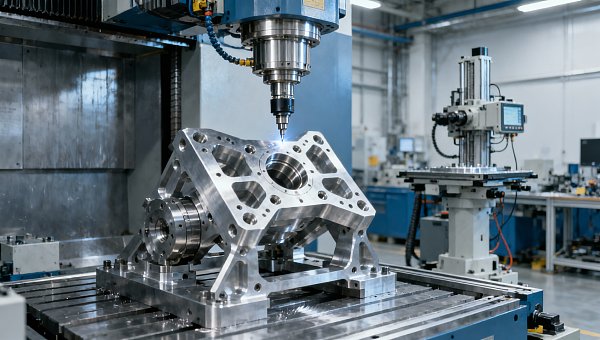
A common oversight in custom machining for robotics joints is focusing only on single-part tolerance instead of stack-up tolerance. A housing bore within print may still cause assembly issues if the flange flatness, shoulder depth, and shaft journal geometry combine unfavorably. In production, three acceptable parts can still produce one unacceptable joint.
Typical consequences of poor machining control
The first consequence is degraded repeatability. A robot designed for ±0.03 mm path repeatability can drift beyond specification if joint alignment errors accumulate across 4 to 6 axes. The second is premature wear. Misaligned bearings or gear stages often show abnormal temperature rise within the first 200–500 operating hours.
The third is assembly inefficiency. Teams may spend extra 2–6 hours per unit on shimming, selective fitting, or troubleshooting vibration. For project schedules with 20, 50, or 100 machines, these delays quickly become a major cost center.
The table below summarizes how machining variables in robotics joints translate into performance and sourcing risk. It can help project managers connect drawing requirements with field outcomes before supplier nomination.
The key takeaway is simple: custom machining for robotics joints should be reviewed as a system-level quality driver, not a commodity part process. Dimensional capability, surface integrity, and geometric consistency all need to be aligned with the robot’s duty cycle and motion profile.
Tolerance Strategy: What Really Matters in Robotics Joints
Not every feature on a robotics joint needs ultra-tight tolerance. Over-tolerancing can increase cost by 15%–40%, extend lead time by 1–3 weeks, and reduce supplier options without improving performance. The right strategy is to identify function-critical dimensions and match them to the application’s actual risk level.
Function-critical dimensions to prioritize
For most joint assemblies, four feature groups deserve the highest attention: bearing fits, shaft journals, gearbox mounting faces, and encoder alignment references. These dimensions directly influence backlash, stiffness, thermal growth, and repeatability. Cosmetic surfaces or non-mating external profiles usually do not need the same control level.
Tolerance planning by application class
- Precision assembly robots: prioritize concentricity, perpendicularity, and low runout.
- Heavy payload manipulators: prioritize bearing seat integrity, housing stiffness, and fatigue margins.
- Mobile robots and AGVs: prioritize shock resistance, sealing surfaces, and maintainable fit classes.
- Outdoor or UAV systems: prioritize mass reduction, corrosion resistance, and thermal dimensional stability.
A practical review method is to split features into three levels. Level 1 includes mission-critical dimensions with low tolerance to deviation. Level 2 includes assembly-support features that need consistency but not extreme precision. Level 3 includes non-critical geometry where standard machining capability is acceptable. This 3-tier model helps procurement teams compare quotations on a rational basis.
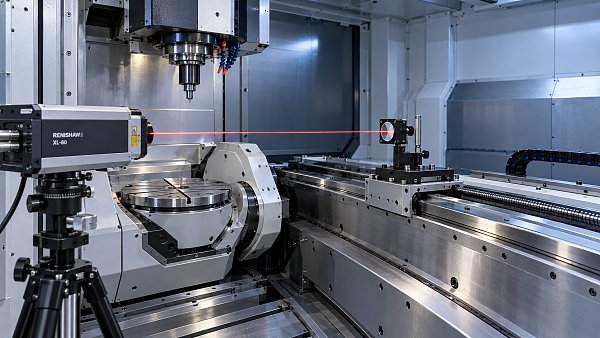
In custom machining for robotics joints, geometric dimensioning often matters more than simple linear dimensions. A shaft diameter can be correct, yet the joint can still fail if total indicated runout exceeds acceptable limits. This is why drawing review should cover datum structure, inspection method, and measurement equipment, not just nominal size.
Material Selection: Balancing Strength, Weight, Wear, and Cost
Material choice in robotics joints is rarely about maximum strength alone. Project teams usually need a balanced combination of stiffness, machinability, fatigue resistance, corrosion behavior, and cost stability. A material that machines quickly may lack wear performance; a high-strength alloy may increase tool wear, inspection difficulty, and total part cost.
Common materials used in joint components
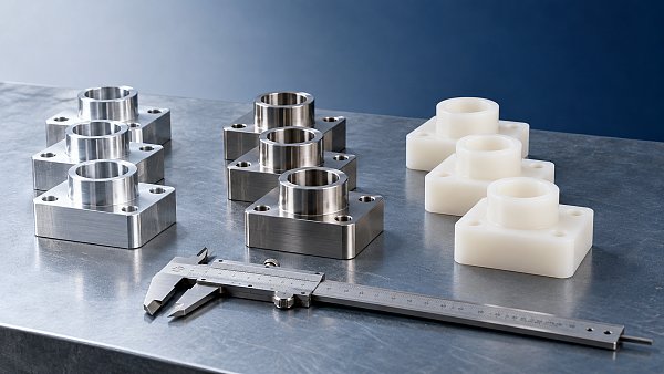
Aluminum alloys are often selected for lightweight housings in cobots, UAV gimbals, and mobile systems. Steel alloys are common in shafts, bearing carriers, and torque-bearing features. Stainless steel appears where washdown, humidity, or chemical exposure matters. Titanium and specialty alloys may be used when weight reduction and corrosion resistance justify significantly higher machining cost.
The table below compares typical material options for custom machining for robotics joints from a project decision perspective, not only a design perspective.
For many programs, the most effective approach is mixed-material design. For example, an aluminum housing paired with hardened steel inserts or shafts can reduce overall mass while preserving wear resistance at critical interfaces. This often delivers better commercial results than forcing one material across all components.
Material questions project teams should ask suppliers
- Is the selected material stable under the expected operating temperature range, such as -10°C to 60°C?
- Will heat treatment or anodizing distort critical bores beyond acceptable limits?
- Can the supplier maintain traceability for each batch and revision?
- Are surface treatments compatible with bearing fits, threads, and sealing features?
These questions matter because some failures attributed to “design weakness” are actually material-process mismatches. A part may pass incoming inspection but still shift dimensionally after coating, stress relief, or repeated thermal cycling in service.
Failure Risks in Custom Machining for Robotics Joints
Failure risk in robotics joints usually develops gradually rather than through a single dramatic event. Most issues begin as small deviations in geometry, surface finish, fit, or process control, then amplify under repetitive load. For a joint cycling 500,000 to 2,000,000 times per year, small imperfections become reliability events.
Most common machining-related failure modes
- Bearing creep caused by incorrect fit or poor bore roundness.
- Crack initiation at sharp internal corners or poor surface transitions.
- Backlash growth from interface wear and misalignment.
- Excessive vibration due to runout, imbalance, or weak datum control.
- Seal failure from groove inaccuracies or damaged surface finish.
- Fastener loosening from soft threads or insufficient seating flatness.
Among these, fatigue-related cracking is especially important for arms, mobile manipulators, and UAV payload systems. Features that look acceptable in a static load review may fail under 10 Hz to 50 Hz repetitive motion if local stress concentration is high. Fillet quality, machining marks, and residual stress all influence this outcome.
Where project risk usually hides
Risk often hides in supplier transition, prototype-to-production scaling, and revision changes. A prototype machined on one setup with hand-selected inspection may perform well, while a 200-piece production run on a different fixture strategy shows variable coaxiality or inconsistent surface finish. This is why process repeatability matters as much as first-article success.
Another hidden risk is incomplete inspection planning. If the control plan measures only diameter and ignores cylindricity, perpendicularity, or bore position, critical defects may escape. For custom machining for robotics joints, dimensional acceptance should mirror actual mechanical function rather than rely only on generic shop checks.
How to Evaluate Suppliers and Control Delivery Risk
Choosing a supplier for robotics joint components is not only about price per part. Project teams should assess machining capability, process discipline, measurement infrastructure, and communication quality. In many programs, a lower quote becomes more expensive after rework, delayed assembly, or field service intervention.
A practical 6-point qualification checklist
- Confirm experience with rotating assemblies, bearing fits, and precision bores.
- Review inspection capability such as CMM, surface roughness testing, and runout measurement.
- Check whether process documentation supports stable batch production over 50, 100, or 500 units.
- Evaluate how engineering changes are controlled across drawings, fixtures, and programs.
- Request sample reports for critical dimensions and geometric tolerances.
- Clarify lead time for prototypes, pilot runs, and repeat orders, such as 2–3 weeks versus 6–8 weeks.
The supplier review should also include manufacturability feedback. A capable partner will flag unnecessary tolerance compression, difficult corner radii, coating risks, or thread durability concerns before production starts. That kind of early input can shorten development cycles and reduce engineering change orders later.
Documentation that helps prevent downstream issues
For critical programs, ask for a first article inspection report, material certificate, process route summary, and key-dimension capability evidence. On higher-risk parts, pilot validation using 5 to 20 assemblies is often more useful than approving one perfect sample. The goal is to confirm repeatable production behavior, not isolated success.
At the sourcing stage, project leaders should connect commercial terms to technical risk. If the joint is central to uptime or safety, it may be worth paying more for traceability, tighter control plans, and validated batch consistency. That decision is often cheaper than reacting to field failures after deployment.
Implementation Guidance for Project Leaders
The most effective way to manage custom machining for robotics joints is to align design, procurement, and validation from the start. Teams that treat machining as a late purchasing step often discover tolerance or material issues after assembly, when corrective action is slower and more expensive.
Recommended execution sequence
- Define critical-to-function dimensions and acceptable failure risks.
- Select material and finishing routes based on duty cycle and environment.
- Review drawings with potential suppliers for manufacturability feedback.
- Validate prototypes with dimensional inspection and functional assembly checks.
- Run pilot production and monitor variation before full release.
For organizations managing multiple robot platforms, standardizing joint interface logic can also reduce complexity. If bearing seat conventions, fastener strategies, and inspection requirements are harmonized across product families, supplier onboarding becomes faster and quality learning transfers more effectively from one project to the next.
Custom machining for robotics joints is ultimately a decision about engineering truth over marketing claims. The teams that win are usually the ones that ask for real tolerances, measurable process controls, and realistic material performance—not generic promises.
For project managers, the priority is clear: define critical tolerances, choose materials based on operating reality, identify failure modes early, and qualify suppliers on process capability rather than surface-level claims. That approach improves repeatability, reduces rework, and protects program schedules.
If your team is evaluating custom machining for robotics joints and needs clearer guidance on tolerance allocation, material selection, or supplier benchmarking, contact us to discuss your application, request a tailored review framework, or explore more precision manufacturing solutions.
Search News
Hot Articles
- Carbon Fiber StructuresHow to Specify Aerospace Carbon Fiber Assemblies for Lightweight, Load-Bearing PartsJul 11, 2026
- Machine VisionXiaomi, Alibaba DAMO Academy Drive Open-Source Robotics Model Ecosystem, Lowering Algorithm Development Barriers for Overseas SMEs Adopting Chinese Robotics SolutionsMar 30, 2026
- Cobots & ArmsShanxi 'AI+' Conference Showcases Embodied Intelligence with Multinational Buyer Engagement: Key Industry ImplicationsMar 30, 2026
Popular Tags
Recommended News
 Jul 11, 2026How to Specify Aerospace Carbon Fiber Assemblies for Lightweight, Load-Bearing PartsAerospace carbon fiber assemblies: learn how to specify laminate design, load data, joining methods, and inspection controls for lighter, reliable load-bearing aerospace parts.Elena Rostova (UAV Systems Researcher)
 Mar 30, 2026Xiaomi, Alibaba DAMO Academy Drive Open-Source Robotics Model Ecosystem, Lowering Algorithm Development Barriers for Overseas SMEs Adopting Chinese Robotics SolutionsXiaomi & Alibaba DAMO Academy's open-source robotics models lower algorithm barriers for global SMEs. Boost efficiency in manufacturing, logistics & smart retail with ROS 2 compatible solutions.TSV Data Lab
 Mar 30, 2026Shanxi 'AI+' Conference Showcases Embodied Intelligence with Multinational Buyer Engagement: Key Industry ImplicationsShanxi 'AI+' Conference highlights embodied intelligence with Tesla, Ubtech & Jiantao showcasing multimodal robotics. 40+ global buyers validated tech on-site, creating new B2B channels for industrial automation & AI solutions.Chen Wei (Automation Lead Engineer)
 Mar 30, 2026Zhongguancun Unveils 6G Integrated Sensing-Computing-Intelligence Platform to Empower Embodied Robots for Global Industrial ApplicationsZhongguancun's new 6G platform revolutionizes industrial robotics with <10ms latency, empowering global automotive, logistics & port automation. Discover how this tech boosts China's smart manufacturing exports.TSV Data Lab
 Mar 30, 2026Mech-Mind Tianjin Embodied Intelligence R&D and Production Base Goes Live, Cutting Delivery Time by 20%–30% for Global Customized AMR+Vision SolutionsMech-Mind's Tianjin AMR+Vision production base cuts delivery time by 20%-30% for欧美 & Latin American markets. Discover how this PLd-certified facility accelerates customized robotics solutions for smart manufacturing and logistics.Chen Wei (Automation Lead Engineer)
 Mar 30, 2026Boao Forum Reveals 'Co-evolution of Big and Small Brains' Trend in Humanoid Robots, China's Embodied Intelligence Accelerates Adaptation to Overseas Manufacturing Service ScenariosDiscover how China's humanoid robots, featuring 'Co-evolution of Big and Small Brains,' are revolutionizing global manufacturing. Learn about Embodied Tian Gong 3.0's ISO compliance and overseas deployment at Boao Forum 2026.Chen Wei (Automation Lead Engineer)
 Mar 30, 2026China Railway Industrial Secures Patent for Embodied Robotics in Material Handling, Boosting High-Precision Delivery Capabilities for Overseas Infrastructure and Manufacturing ProjectsChina Railway Industrial's new patent for embodied robotics in material handling boosts high-precision delivery for global infrastructure & manufacturing. Discover how this innovation enhances logistics accuracy in automotive, rail transit & EPC projects.Chen Wei (Automation Lead Engineer)
 Oct 18, 2026Comparing Material Options for Procurement: Specs, Costs, and Supply RisksExplore procurement oriented technical content on material options, specs, costs, and supply risks. Compare alternatives to cut hidden expenses and make confident sourcing decisions.Dr. Marcus Vance
 Oct 17, 20265-Axis CNC Positioning Accuracy: How to Interpret ISO 230-2 Test ResultsAssess 5 axis CNC machining positioning accuracy with ISO 230-2. Learn to interpret repeatability, reversal error, and test conditions to compare suppliers and make confident acceptance decisions.Dr. Marcus Vance
 Oct 16, 2026Choosing a Rugged Edge AI Box Supplier: Thermal Tests and Lifecycle SupportChoose a rugged edge AI box supplier with proven thermal performance and reliable lifecycle support. Discover the tests and commitments to verify before you buy.TSV Data Lab
 Oct 15, 2026R&D Cost Reduction Services: How to Evaluate Fees, Savings, and ROIEvaluate R&D cost reduction services with confidence. Compare fees, verify savings, and calculate ROI without compromising performance. Discover how to choose a provider that delivers real value.Chen Wei (Automation Lead Engineer)
 Oct 17, 2026How Should You Interpret Industrial Robot Repeatability Specs?Decode industrial robot repeatability specifications, understand ISO 9283 test conditions, and avoid costly selection mistakes. Learn how to verify performance for your process.Chen Wei (Automation Lead Engineer)
 Oct 16, 2026How Can You Fairly Compare MTBF Across Industrial Servo Motors?Make a fair industrial servo motor MTBF comparison with matched operating profiles, failure criteria, and confidence bounds. Discover how to assess reliability beyond advertised numbers.Chen Wei (Automation Lead Engineer)
 Oct 15, 2026How Should You Compare TechStat Vanguard 5-Axis CNC Tolerances?TechStat Vanguard 5-axis CNC tolerance comparison: learn how to verify part accuracy, assess inspection evidence, and choose suppliers that reliably meet your drawing requirements.Dr. Marcus Vance
 Oct 14, 2026Drone Frame Composites: Carbon Fiber vs. Fiberglass for Weight and StiffnessExplore drone structural materials composites: compare carbon fiber and fiberglass for weight, stiffness, cost, and antenna compatibility. Find the right material for your drone frame.Elena Rostova (UAV Systems Researcher)
 Oct 13, 2026Smart Cameras vs. PC-Based Machine Vision: Which Fits High-Speed Inspection?This industrial product comparison for machine vision weighs smart cameras vs. PC-based systems on latency, throughput, and cost. Discover your best fit for high-speed inspection.TSV Data Lab
 Oct 12, 2026How to Verify RoHS Compliance in Industrial Sensing Systems Before DeploymentRoHS compliant sensing systems: learn how to verify materials, supplier declarations, testing, and configuration controls before industrial deployment.TSV Data Lab
 Oct 11, 2026How Procurement-Oriented Content Taxonomy Improves B2B Buying JourneysProcurement-oriented content taxonomy streamlines B2B buying journeys with clearer evidence, supplier comparisons, risk visibility, and faster approvals.TSV Data Lab
 Oct 10, 2026How to Select a Machine Performance Monitoring Platform for OEE and Downtime ReductionMachine performance monitoring platform selection guide: validate machine states, OEE data, downtime reasons, integrations, and scalability to reduce losses with confidence.TSV Data Lab
 Oct 08, 2026How to Machine Inconel 625 Blades Without Heat Cracks or Edge ChippingInconel 625 blade machining guide: prevent heat cracks, edge chipping, chatter, and work hardening with proven tooling, cooling, fixturing, and inspection strategies.Dr. Marcus Vance
 Oct 07, 2026How to Evaluate an HMI Panel Distributor for Industrial Automation ProjectsHMI panel distributor evaluation guide: verify technical compatibility, traceability, supply reliability, lifecycle support, and total cost for automation projects.Victor Lin (Chief Software Architect)
 Oct 06, 2026Navigation Fault Tolerance Standards for AMRs: What Safety Teams Must VerifyNavigation fault tolerance standards: learn what AMR safety teams must verify, from localization loss and sensor faults to stopping distance, safe restart, and site-specific validation.Chen Wei (Automation Lead Engineer)
 Oct 05, 2026Calculating Edge Computing Total Cost of Ownership Across Distributed SitesEdge computing ownership cost explained: calculate deployment, energy, connectivity, security, remote support, and refresh costs across distributed sites.TSV Data Lab
 Oct 04, 2026CAD/CAM Benchmarking in the GCC: What Manufacturers Should Ask a ConsultantCAD CAM benchmark consultant GCC guide: learn the key questions manufacturers should ask to validate post-processors, workflows, machine performance, and production risk.Victor Lin (Chief Software Architect)