How to Evaluate Drone Payload Bandwidth for Real-Time Sensors and Video
Publication Date
author
How to Evaluate Drone Payload Bandwidth for Real-Time Sensors and Video
Evaluating drone payload bandwidth is essential when real-time sensors and video must operate without latency, packet loss, or unstable data flow. For technical assessment teams, the challenge is not just total throughput, but how payload interfaces, encoding loads, telemetry channels, and mission conditions interact under real operating constraints. This article outlines a data-driven framework to assess drone payload bandwidth with engineering precision, helping decision-makers compare platforms, reduce integration risk, and validate performance before deployment.
In practice, drone payload bandwidth is often misunderstood because vendor literature tends to present a single “maximum data rate” as if it defines mission readiness. It does not. A UAV that can theoretically move high data volumes through an onboard bus may still fail a real-time inspection, mapping, surveillance, or edge-AI mission if the radio link is unstable, the encoder adds excessive latency, the processor cannot sustain simultaneous sensor pipelines, or the storage subsystem becomes the hidden bottleneck.
For technical evaluators, the useful question is not “What is the peak bandwidth?” but “What data can be moved, processed, stored, and transmitted within the mission latency budget under actual operating conditions?” That distinction separates brochure claims from engineering suitability.
Bandwidth evaluation starts with the mission data model
Any serious assessment begins by defining the payload data model at mission level. A drone carrying one 1080p daylight camera has a very different bandwidth profile from a platform carrying dual EO/IR video, LiDAR, GNSS/INS correction streams, and a command-and-control uplink operating at the same time.
Technical teams should map every data-producing and data-consuming element in the chain:
- Primary sensors: RGB video, thermal imagers, multispectral cameras, LiDAR, radar, gas sensors, machine vision modules
- Navigation and state data: GNSS, IMU, air data, RTK corrections, health monitoring
- Control and telemetry channels: command uplink, payload control, flight logs, status feedback
- Onboard computing: AI inference, compression, sensor fusion, object tracking, stabilization
- Storage and forwarding paths: local SSD, removable media, edge buffering, downlink transmission
- Ground segment requirements: live monitoring, recording, cloud relay, operator display, analytics
Only after this mapping exercise can bandwidth be sized correctly. Otherwise, teams tend to either overspecify expensive airframes or underestimate integration risk.
A practical method is to create a mission matrix with four columns: source data rate, sustained data rate, latency tolerance, and packet-loss tolerance. This quickly exposes which streams are safety-critical, which are mission-critical, and which can tolerate buffering or compression.
Raw sensor output is rarely the number that matters
One common error in payload evaluation is relying on raw sensor throughput while ignoring how the data will actually be handled. Real-time video is the clearest example. An uncompressed 1080p or 4K stream can require data rates far beyond what many field radio links can sustain continuously, but onboard encoding may reduce this dramatically. The tradeoff is that encoding introduces its own constraints: processor load, thermal dissipation, compression artifacts, and end-to-end latency.
LiDAR creates a similar problem. Vendors may describe point cloud generation rates, but the operational issue is whether the system transmits raw packets, filtered packets, feature-extracted packets, or only event-based outputs. The answer changes both bandwidth and onboard compute requirements.
Technical evaluators should separate payload data into three layers:
- Raw acquisition bandwidth: sensor-native output before compression, filtering, or fusion
- Internal transport bandwidth: what moves through onboard buses between sensor, processor, storage, and radio
- External transmission bandwidth: what must reach the ground station or downstream network in real time
These three values are often very different. A system can be acceptable on one layer and completely inadequate on another.
Interface architecture usually decides the real ceiling
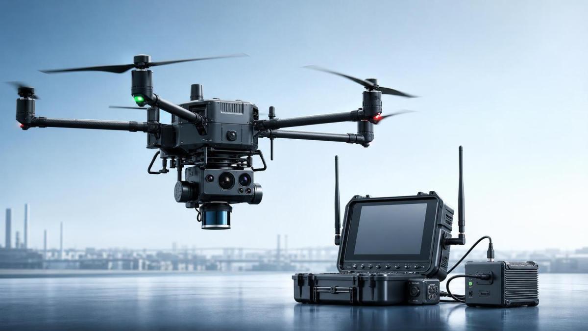
When bandwidth problems emerge in UAV payload integration, the root cause is often not the sensor and not the radio, but the interface architecture between them. USB 3.x, Ethernet, MIPI CSI, SDI, HDMI, serial links, CAN, and proprietary payload connectors all behave differently under vibration, cable length constraints, EMI exposure, and thermal cycling.
From an evaluation standpoint, there are several engineering questions that matter more than the nominal interface speed listed on a datasheet:
- Is the stated throughput full duplex or half duplex?
- Is the data rate sustained or burst only?
- What protocol overhead reduces usable throughput?
- How many devices share the same bus or switch fabric?
- Does the flight computer contend for the same resources?
- What happens when multiple sensors peak simultaneously?
For example, a payload stack may look sufficient if each sensor is considered independently. But once video, telemetry, and AI processing all compete for memory bandwidth and bus arbitration, frame drops can appear even though no single subsystem exceeds its own nominal specification.
This is why technical assessment should treat onboard bandwidth as a system resource, not a sensor attribute.
Latency budget matters as much as throughput
Real-time missions fail because of latency just as often as because of insufficient throughput. For inspection, public safety, perimeter monitoring, or remote piloting support, the relevant engineering target is usually end-to-end delay: sensor capture to operator display or machine response.
A payload architecture may support adequate megabits per second yet still be operationally poor if latency accumulates across:
- Sensor readout
- Image signal processing
- Compression and packetization
- Onboard buffering
- Wireless link scheduling
- Ground station decoding and rendering
In technical reviews, teams should define an explicit latency budget per stream. A stabilized surveillance camera used for human-in-the-loop observation can tolerate some delay; a machine vision payload guiding close-proximity navigation or triggering time-sensitive inspection events may not.
Latency should also be measured under network impairment, not only in ideal lab conditions. Jitter, retransmission behavior, and congestion control can make a link that appears adequate in average throughput terms behave unpredictably in the field.
Wireless link claims need field-condition derating
Air-to-ground data links are a major source of overestimation in drone payload bandwidth planning. Vendor-stated link rates are often derived under clean spectrum, favorable antenna orientation, short range, and ideal line-of-sight assumptions. Real missions introduce distance, interference, urban reflections, foliage, platform attitude changes, weather effects, and competing RF traffic.
For technical assessment teams, the only defensible approach is derating. If a link advertises a certain peak throughput, the mission plan should be sized against a lower sustained value validated in representative conditions. The derating factor depends on band, modulation, antenna design, channel width, environment, and mobility profile; there is no single universal percentage that can be responsibly stated across systems.
What matters is that bandwidth evaluation include at least these stress conditions:
- Maximum intended range
- Worst expected RF interference zone
- Banking and yaw attitudes that alter antenna geometry
- Simultaneous operation of all mission payloads
- Temperature conditions affecting electronics and battery voltage stability
If the mission depends on beyond visual line of sight operations, additional regulatory and communication architecture factors may apply, including spectrum authorization and command-link resilience requirements. Exact compliance obligations vary by jurisdiction and use case and should be treated as program-specific rather than assumed.
Compression is not free bandwidth
Many integration plans resolve bandwidth pressure by assuming that video compression will solve the problem. Sometimes it does. Just as often, it shifts the problem elsewhere.
Compression changes the system in at least four ways:
- It reduces transport demand
- It increases compute load
- It may increase latency
- It can degrade analytic quality for downstream AI or inspection tasks
This is especially relevant when the same video stream serves two purposes at once: live viewing and machine analysis. A highly compressed stream may look acceptable to an operator but perform poorly for defect detection, tracking, or low-contrast thermal interpretation.
Technical evaluators should therefore ask not only which codec is used, but also:
- What bitrate is needed at mission image quality thresholds?
- How does motion complexity affect bitrate variability?
- Is bitrate fixed, capped, or adaptive?
- What is the encode/decode latency under sustained load?
- Does the processor throttle thermally during long flights?
A bandwidth design that works for short bench tests may collapse after twenty minutes of sustained airborne encoding in high ambient temperature.
Storage and buffering are part of bandwidth assurance
Not all payload data must be transmitted in real time, but if it is not transmitted, it must be buffered or stored reliably. This makes onboard storage performance part of the bandwidth evaluation, particularly in mapping, inspection, and forensic capture missions where raw or near-raw data must be preserved.
Teams should examine sustained write speed, not only drive interface rating. Solid-state media can show high burst performance and then degrade when cache is exhausted, temperature rises, or fragmented writes accumulate. If video, LiDAR, and logs all write concurrently, actual sustained performance may differ sharply from benchmark values measured in isolation.
Good evaluation practice includes fault scenarios: what happens if the downlink rate drops suddenly? Does the system buffer without frame loss? Is there stream prioritization? Are critical telemetry and command paths protected from payload traffic saturation?
These details matter more than generic claims of “real-time transmission capability.”
Sensor concurrency is where many platforms are exposed
A platform that handles one payload cleanly may struggle when multiple real-time sensors operate together. Concurrency stress reveals whether the architecture is genuinely scalable or merely adequate for a demonstration setup.
Typical problem combinations include:
- 4K visible video plus thermal video plus telemetry
- LiDAR streaming plus RTK correction plus onboard mapping preview
- Machine vision inference plus recording plus live operator feed
- Gimbal control traffic interacting with video transport on shared resources
Evaluation should focus on worst-case simultaneous demand, not average mission demand. The key metrics are sustained throughput, latency under peak load, packet loss, dropped frames, processor utilization, memory utilization, and thermal margin.
Concurrency testing is also where hidden software limitations appear. Driver inefficiency, thread scheduling, interrupt contention, and middleware bottlenecks can reduce usable payload bandwidth long before physical interfaces are saturated.
Use a validation framework, not a datasheet checklist
For technical assessment teams comparing drone platforms, a structured validation method is more useful than a feature-by-feature comparison table. A practical framework typically includes:
- Requirement definition: sensor set, frame rates, resolution, latency limits, recording needs, live link needs
- Architecture review: interfaces, onboard buses, compute topology, storage path, RF path
- Bandwidth budget: per stream and aggregate, with protocol overhead and derating
- Latency budget: stage-by-stage from acquisition to consumption
- Environmental validation: EMI, thermal load, vibration, range, interference
- Failure-mode testing: link degradation, storage fallback, compute overload, recovery behavior
This process is slower than accepting headline specifications, but it is far cheaper than discovering in deployment that a platform cannot maintain stable sensor output during actual missions.
What to request from suppliers during technical assessment
Supplier discussions around drone payload bandwidth are often imprecise unless the buyer forces the conversation into measurable engineering terms. Useful requests include:
- Sustained throughput data, not only peak interface rates
- End-to-end latency measurements with test conditions stated
- Maximum concurrent payload combinations officially supported
- Processor utilization and thermal data during continuous operation
- Packet loss or frame-drop statistics under degraded link conditions
- Onboard recording limits with simultaneous downlink active
- Protocol details and overhead assumptions
- EMI and vibration validation evidence for payload interfaces
If such data is unavailable, the technical risk should be treated as real, not theoretical. In UAV procurement, undocumented performance boundaries often become integration delays, redesign cycles, or field reliability issues.
The most common evaluation mistake
The most common mistake is treating bandwidth as a single number rather than a chain of constraints. Real-time UAV sensing depends on the weakest point across sensing, processing, transport, storage, wireless transmission, and display. A generous margin in one part of the chain does not compensate for instability in another.
That is why a rigorous drone payload bandwidth assessment looks less like a simple network sizing exercise and more like systems engineering. Technical teams need to know what data is essential, what delay is tolerable, what can be compressed, what must be preserved, and how performance shifts when the aircraft is no longer in the lab.
For organizations evaluating platforms for inspection, mapping, surveillance, or autonomous edge sensing, the most reliable decision comes from integrated validation under mission-like load. Peak bandwidth numbers are easy to publish. Sustained, low-latency, multi-sensor performance under airborne constraints is what actually determines whether a payload architecture is deployable.
Search News
Hot Articles
- Carbon Fiber StructuresHow to Specify Aerospace Carbon Fiber Assemblies for Lightweight, Load-Bearing PartsJul 11, 2026
- Machine VisionXiaomi, Alibaba DAMO Academy Drive Open-Source Robotics Model Ecosystem, Lowering Algorithm Development Barriers for Overseas SMEs Adopting Chinese Robotics SolutionsMar 30, 2026
- Cobots & ArmsShanxi 'AI+' Conference Showcases Embodied Intelligence with Multinational Buyer Engagement: Key Industry ImplicationsMar 30, 2026
Popular Tags
Recommended News
 Jul 11, 2026How to Specify Aerospace Carbon Fiber Assemblies for Lightweight, Load-Bearing PartsAerospace carbon fiber assemblies: learn how to specify laminate design, load data, joining methods, and inspection controls for lighter, reliable load-bearing aerospace parts.Elena Rostova (UAV Systems Researcher)
 Mar 30, 2026Xiaomi, Alibaba DAMO Academy Drive Open-Source Robotics Model Ecosystem, Lowering Algorithm Development Barriers for Overseas SMEs Adopting Chinese Robotics SolutionsXiaomi & Alibaba DAMO Academy's open-source robotics models lower algorithm barriers for global SMEs. Boost efficiency in manufacturing, logistics & smart retail with ROS 2 compatible solutions.TSV Data Lab
 Mar 30, 2026Shanxi 'AI+' Conference Showcases Embodied Intelligence with Multinational Buyer Engagement: Key Industry ImplicationsShanxi 'AI+' Conference highlights embodied intelligence with Tesla, Ubtech & Jiantao showcasing multimodal robotics. 40+ global buyers validated tech on-site, creating new B2B channels for industrial automation & AI solutions.Chen Wei (Automation Lead Engineer)
 Mar 30, 2026Zhongguancun Unveils 6G Integrated Sensing-Computing-Intelligence Platform to Empower Embodied Robots for Global Industrial ApplicationsZhongguancun's new 6G platform revolutionizes industrial robotics with <10ms latency, empowering global automotive, logistics & port automation. Discover how this tech boosts China's smart manufacturing exports.TSV Data Lab
 Mar 30, 2026Mech-Mind Tianjin Embodied Intelligence R&D and Production Base Goes Live, Cutting Delivery Time by 20%–30% for Global Customized AMR+Vision SolutionsMech-Mind's Tianjin AMR+Vision production base cuts delivery time by 20%-30% for欧美 & Latin American markets. Discover how this PLd-certified facility accelerates customized robotics solutions for smart manufacturing and logistics.Chen Wei (Automation Lead Engineer)
 Mar 30, 2026Boao Forum Reveals 'Co-evolution of Big and Small Brains' Trend in Humanoid Robots, China's Embodied Intelligence Accelerates Adaptation to Overseas Manufacturing Service ScenariosDiscover how China's humanoid robots, featuring 'Co-evolution of Big and Small Brains,' are revolutionizing global manufacturing. Learn about Embodied Tian Gong 3.0's ISO compliance and overseas deployment at Boao Forum 2026.Chen Wei (Automation Lead Engineer)
 Mar 30, 2026China Railway Industrial Secures Patent for Embodied Robotics in Material Handling, Boosting High-Precision Delivery Capabilities for Overseas Infrastructure and Manufacturing ProjectsChina Railway Industrial's new patent for embodied robotics in material handling boosts high-precision delivery for global infrastructure & manufacturing. Discover how this innovation enhances logistics accuracy in automotive, rail transit & EPC projects.Chen Wei (Automation Lead Engineer)
 Sep 21, 2026Drone Payload Integration: Matching Power, Data, and Center of Gravity for Reliable FlightsDrone payload integration made practical: balance power, data, center of gravity, and endurance to build safer, more reliable mission-ready flights.Elena Rostova (UAV Systems Researcher)
 Sep 20, 2026Autonomous Navigation Pricing: Cost Drivers and Budget Benchmarks for AMR ProjectsAutonomous navigation price explained: compare AMR cost drivers, software, sensors, integration, safety, and lifecycle budgets to build a scalable project plan.Chen Wei (Automation Lead Engineer)
 Sep 19, 2026How to Scope Automation Integration Services for Multi-System Factory ProjectsAutomation integration services: learn how to scope multi-system factory projects with clear workflows, interface contracts, safety boundaries, and acceptance criteria.Victor Lin (Chief Software Architect)
 Sep 18, 2026Selecting UAV Aerospace Structural Parts for Strength, Weight, and Fatigue LifeUAV aerospace structural parts guide: compare strength, weight, stiffness, fatigue life, joints, and traceability to select reliable flight-ready components.Elena Rostova (UAV Systems Researcher)
 Sep 17, 2026Selecting Commercial Drone Payloads for European Inspection ProjectsCommercial drone payloads Europe: learn how to select RGB, thermal and LiDAR systems for compliant, reliable inspection data and better project outcomes.Elena Rostova (UAV Systems Researcher)
 Sep 16, 2026Machining Tolerance Validation: How to Verify Critical Dimensions Before Production ReleaseMachining tolerance analysis validation: verify critical dimensions, measurement systems, process capability, and tolerance stacks before production release.Dr. Marcus Vance
 Sep 15, 2026AGV Tape Guidance vs Laser Navigation: Which Fits Your Warehouse Layout?AGV tape guidance comparison: discover how tape and laser navigation fit changing warehouse layouts, docking needs, floor conditions, maintenance, and route flexibility.Chen Wei (Automation Lead Engineer)
 Sep 14, 2026How Point Cloud Analytics Improves Asset Inspection Workflows Across GCC ProjectsPoint cloud analytics GCC helps project leaders improve asset inspections with accurate change detection, safer workflows, and faster maintenance decisions.TSV Data Lab
 Sep 13, 2026How Aerospace Manufacturers Can Build a Digital Thread From Design to Certified ProductionDigital manufacturing for aerospace: learn how to build a traceable digital thread from design through certified production, supplier control, and audit-ready compliance.Victor Lin (Chief Software Architect)
 Sep 12, 2026How to Select a Thermal Sensor for Mapping Drones in Surveying ProjectsMapping drone thermal sensor selection made simple: compare GSD, radiometric data, NETD, calibration, and workflow fit for accurate, survey-ready thermal maps.Elena Rostova (UAV Systems Researcher)
 Sep 11, 2026Integrating Photogrammetry Workflows into Digital Twin Projects Without Data BottlenecksPhotogrammetry workflow integration for digital twins: learn how to streamline capture, validation, versioning, and delivery to prevent data bottlenecks.Victor Lin (Chief Software Architect)
 Sep 10, 2026Hard-Tech Supply Chain Procurement: Qualifying Suppliers to Cut Lead-Time RiskHard-tech supply chain procurement guide: qualify suppliers with proven process, traceability, capacity, and change control to reduce lead-time risk.Chen Wei (Automation Lead Engineer)
 Sep 09, 2026Industrial Application Notes: Cost Factors That Shape Automation Project BudgetsIndustrial application notes cost factors explained: uncover the engineering, safety, integration, and commissioning variables that shape accurate automation budgets.Victor Lin (Chief Software Architect)
 Sep 08, 2026Supplier Discovery for Sourcing: How Buyers Can Verify Capability and Supply RiskSupplier discovery for sourcing: learn how to verify supplier capability, traceability, quote assumptions, and supply risk before placing production orders.TSV Data Lab
 Sep 07, 2026What Determines Process Control Systems Pricing? A Buyer’s Cost GuideProcess control systems pricing explained: compare hardware, engineering, integration, cybersecurity, validation, and lifecycle costs to choose the right-value solution.Victor Lin (Chief Software Architect)
 Sep 07, 2026AMR Robots in ASEAN: Which Industries Are Adopting Them—and Why?AMR robots ASEAN adoption is accelerating in electronics, automotive, warehousing, healthcare, and cold chain. Explore use cases, risks, and deployment insights.Chen Wei (Automation Lead Engineer)
 Sep 05, 2026How to Evaluate Supplier Qualification Support Tools for Industrial Procurement TeamsSupplier qualification support tools help industrial procurement teams verify technical evidence, manage risk, and make defensible supplier approvals. Learn what to evaluate.Victor Lin (Chief Software Architect)