How to Specify Custom Machining for Robotics Joints: Tolerances, Materials, and Loads
Publication Date
author
Specifying custom machining for robotics joints is less about claiming precision and more about defining what precision must achieve in motion. A joint that tracks accurately in a lab may drift, heat up, or wear early in production if tolerance stacks, material response, and load paths were never translated into a disciplined machining specification.
That is why custom machining for robotics joints has become a sharper topic across automation, UAV subsystems, inspection platforms, and advanced handling equipment. In a market crowded with vague capability statements, the useful question is simple: what exact geometry, material state, and fatigue margin are required for the joint to survive its real duty cycle?
For organizations working from a data-first mindset, the spec sheet is where sourcing risk is either reduced or created. TechStat Vanguard has consistently argued that parameters, not slogans, determine whether a supplier is suitable. Robotics joints are one of the clearest examples of that principle.
What custom machining for robotics joints actually covers
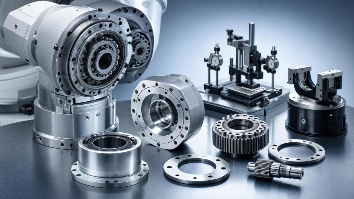
At a practical level, custom machining for robotics joints includes the precision features that define how rotating or pivoting elements align, carry force, and maintain repeatability. That usually means bearing seats, shaft interfaces, housing bores, mounting faces, sealing surfaces, gear interfaces, and datum structures.
The machining requirement changes with the joint architecture. A lightweight collaborative arm, a harmonic drive stage, and a heavy payload wrist joint may all need CNC machining, but they do not fail in the same way.
Some joints are dominated by backlash sensitivity. Others are limited by stiffness, thermal growth, contamination ingress, or fatigue at stress risers. The specification should therefore describe the function of each critical surface, not just the nominal size.
Why the specification stage matters more than supplier claims
The current hard-tech supply chain produces more data than ever, yet reliable decision support is still scarce. Marketing language often compresses major engineering differences into broad phrases such as tight tolerance or aerospace quality.
For robotics joints, those phrases are nearly useless without context. A tolerance that is acceptable for a static bracket may be unacceptable for a rotating joint with encoder feedback, preload-sensitive bearings, and reversal-heavy motion.
This is where a benchmarking mindset helps. The goal is not to request the smallest possible tolerance everywhere. The goal is to tie machining requirements to measurable performance: repeatability, runout, stiffness, friction, heat generation, service life, and maintenance interval.
In other words, custom machining for robotics joints should be specified backward from failure modes and functional targets. That reduces both overengineering and hidden risk.
Tolerance strategy starts with datums and stack behavior
Tolerance is usually discussed as a single number, but joints behave as assemblies. The more useful approach is to define datums, concentricity needs, face flatness, perpendicularity, and cumulative stack effects across the rotating system.
A bearing bore, for example, may hold size within microns and still perform poorly if the mounting face lacks flatness or the bore axis is misaligned to the reference plane. The joint then sees uneven preload, local contact stress, and accelerated wear.
Key tolerance areas often include:
- Bearing seat diameter and cylindricity
- Coaxiality between input and output features
- Flatness of clamping and mounting faces
- Positional accuracy for fastener patterns and dowels
- Surface finish on sealing, sliding, and preload interfaces
In custom machining for robotics joints, geometric tolerancing often matters more than a blanket dimensional tolerance. A compact drawing with clear datum logic is usually more valuable than a crowded drawing full of disconnected limits.
Avoiding the usual tolerance mistakes
One common mistake is placing ultra-tight tolerances on nonfunctional features while leaving critical relationships loosely defined. Another is ignoring process capability for deep bores, thin walls, or distortion-prone parts after heat treatment.
A better specification identifies which features control motion quality and which merely support packaging. That distinction improves manufacturability and makes supplier quotations easier to compare on engineering merit.
Material choice is really about behavior under motion
Material selection for custom machining for robotics joints should not stop at tensile strength. Joint components live under repeated load reversals, contact stress, vibration, lubricant exposure, and local heating near motors or gear trains.
Aluminum alloys may suit weight-sensitive arms and mobile systems, especially where inertia reduction improves response. Steel alloys remain stronger choices for high-contact interfaces, heavy payload joints, and applications where rigidity dominates weight savings.
Stainless grades help in corrosive or washdown environments, but machinability, galling risk, and cost must be balanced carefully. Titanium may help in aerospace-adjacent robotics, though its machining cost and thermal behavior require deliberate justification.
Heat treatment and surface condition also belong in the specification. Hardness range, residual stress risk, anodizing thickness, nitriding depth, coating adhesion, and post-treatment dimensional stability can all change joint performance.
Loads should be defined as real duty cycles, not peak numbers
Many sourcing documents mention only maximum torque or payload. That is rarely enough. Joint life depends on how loads are applied over time, how often they reverse, and where shock enters the structure.
For effective custom machining for robotics joints, the load section should describe static load, dynamic load, bending moment, axial force, radial force, speed range, acceleration profile, and expected cycle count.
It also helps to state whether the joint sees intermittent overloads, emergency stops, collision events, or vibration from adjacent equipment. These conditions influence material choice, fillet design, wall thickness, and inspection requirements.
Where fatigue matters, a single ultimate strength figure is not enough. The specification should ask for fatigue-relevant evidence or at least define the design life assumption behind the machining and material callout.
Load paths deserve explicit attention
A joint rarely fails at the location of highest nominal load. It often fails where the load path is interrupted by a sharp transition, thin flange, bolt pattern imbalance, or misaligned bearing support.
That is why drawings and supplier discussions should identify how force transfers through the machined body. When the load path is visible, critical features become easier to prioritize and inspect.
Different robotics scenarios change the machining priorities
The phrase custom machining for robotics joints covers a wide range of operating environments. What matters most in one system may be secondary in another.
A few common patterns are worth separating:
- Collaborative robots: low friction, smooth motion, compact packaging, thermal stability
- Heavy industrial manipulators: stiffness, impact tolerance, bearing support integrity, fatigue life
- AGV or AMR mechanisms: contamination resistance, weight control, serviceability
- UAV gimbals and aerospace-adjacent joints: low mass, vibration behavior, dimensional stability
- Inspection and medical platforms: quiet motion, low backlash, clean finishes, traceability
This variation is one reason generic supplier capability sheets can mislead. The same machine shop may perform well on one joint family and struggle on another if inspection discipline or fixturing strategy does not match the application.
What a stronger machining specification should include
A usable specification for custom machining for robotics joints connects design intent, process feasibility, and verification. It gives a supplier enough information to manufacture the part correctly and enough structure to quote the risk honestly.
The strongest documents usually include:
- Functional datums and critical-to-motion features
- Material grade, temper, heat treatment, and surface treatment
- Load assumptions, cycle profile, and service life target
- Surface finish limits for bearings, seals, and sliding contacts
- Inspection method for high-risk features, including CMM or runout checks
- Traceability needs for revision control and critical batches
If the part supports a regulated or safety-relevant application, process control expectations should be stated early. That may include first article inspection, material certs, hardness verification, or sampling rules tied to critical dimensions.
How to evaluate next steps with fewer assumptions
A clear next step is to review the current joint drawing and ask whether every tight requirement has a functional reason. Then check whether every functional risk has a measurable parameter attached to it.
That review often reveals the same gaps: missing datum logic, incomplete material state, no duty-cycle definition, and no inspection method for the features that actually govern motion quality.
From there, compare candidate suppliers using evidence that matches the joint type. For custom machining for robotics joints, relevant proof is not generic capability language. It is process capability on similar geometries, inspection discipline, material handling control, and documented performance under comparable loads.
A more dependable sourcing decision starts when the specification speaks the language of tolerances, materials, and loads with enough precision to be tested. That approach fits the broader TSV view of advanced manufacturing: engineering truth becomes visible when requirements are explicit, comparable, and grounded in data.
For any upcoming joint program, the most practical move is to tighten the spec sheet before tightening the supplier shortlist. That sequence usually saves more time, cost, and redesign effort than any late-stage correction.
Search News
Hot Articles
- Carbon Fiber StructuresHow to Specify Aerospace Carbon Fiber Assemblies for Lightweight, Load-Bearing PartsJul 11, 2026
- Machine VisionXiaomi, Alibaba DAMO Academy Drive Open-Source Robotics Model Ecosystem, Lowering Algorithm Development Barriers for Overseas SMEs Adopting Chinese Robotics SolutionsMar 30, 2026
- Cobots & ArmsShanxi 'AI+' Conference Showcases Embodied Intelligence with Multinational Buyer Engagement: Key Industry ImplicationsMar 30, 2026
Popular Tags
Recommended News
 Jul 11, 2026How to Specify Aerospace Carbon Fiber Assemblies for Lightweight, Load-Bearing PartsAerospace carbon fiber assemblies: learn how to specify laminate design, load data, joining methods, and inspection controls for lighter, reliable load-bearing aerospace parts.Elena Rostova (UAV Systems Researcher)
 Mar 30, 2026Xiaomi, Alibaba DAMO Academy Drive Open-Source Robotics Model Ecosystem, Lowering Algorithm Development Barriers for Overseas SMEs Adopting Chinese Robotics SolutionsXiaomi & Alibaba DAMO Academy's open-source robotics models lower algorithm barriers for global SMEs. Boost efficiency in manufacturing, logistics & smart retail with ROS 2 compatible solutions.TSV Data Lab
 Mar 30, 2026Shanxi 'AI+' Conference Showcases Embodied Intelligence with Multinational Buyer Engagement: Key Industry ImplicationsShanxi 'AI+' Conference highlights embodied intelligence with Tesla, Ubtech & Jiantao showcasing multimodal robotics. 40+ global buyers validated tech on-site, creating new B2B channels for industrial automation & AI solutions.Chen Wei (Automation Lead Engineer)
 Mar 30, 2026Zhongguancun Unveils 6G Integrated Sensing-Computing-Intelligence Platform to Empower Embodied Robots for Global Industrial ApplicationsZhongguancun's new 6G platform revolutionizes industrial robotics with <10ms latency, empowering global automotive, logistics & port automation. Discover how this tech boosts China's smart manufacturing exports.TSV Data Lab
 Mar 30, 2026Mech-Mind Tianjin Embodied Intelligence R&D and Production Base Goes Live, Cutting Delivery Time by 20%–30% for Global Customized AMR+Vision SolutionsMech-Mind's Tianjin AMR+Vision production base cuts delivery time by 20%-30% for欧美 & Latin American markets. Discover how this PLd-certified facility accelerates customized robotics solutions for smart manufacturing and logistics.Chen Wei (Automation Lead Engineer)
 Mar 30, 2026Boao Forum Reveals 'Co-evolution of Big and Small Brains' Trend in Humanoid Robots, China's Embodied Intelligence Accelerates Adaptation to Overseas Manufacturing Service ScenariosDiscover how China's humanoid robots, featuring 'Co-evolution of Big and Small Brains,' are revolutionizing global manufacturing. Learn about Embodied Tian Gong 3.0's ISO compliance and overseas deployment at Boao Forum 2026.Chen Wei (Automation Lead Engineer)
 Mar 30, 2026China Railway Industrial Secures Patent for Embodied Robotics in Material Handling, Boosting High-Precision Delivery Capabilities for Overseas Infrastructure and Manufacturing ProjectsChina Railway Industrial's new patent for embodied robotics in material handling boosts high-precision delivery for global infrastructure & manufacturing. Discover how this innovation enhances logistics accuracy in automotive, rail transit & EPC projects.Chen Wei (Automation Lead Engineer)
 Oct 20, 2026Smart Industrial Edge Devices: Key Criteria for Legacy PLC IntegrationChoose smart industrial edge devices for legacy PLC integration. Discover key criteria for compatibility, data quality, security, and reliable collection without disrupting control.TSV Data Lab
 Oct 19, 2026Choosing a Radar Sensor by Application: Range, Resolution, and Field of ViewSimplify radar sensor application based product selection. Compare range, resolution, and field of view to avoid blind spots and choose with confidence. Explore the guide.TSV Data Lab
 Oct 18, 2026Comparing Material Options for Procurement: Specs, Costs, and Supply RisksExplore procurement oriented technical content on material options, specs, costs, and supply risks. Compare alternatives to cut hidden expenses and make confident sourcing decisions.Dr. Marcus Vance
 Oct 17, 20265-Axis CNC Positioning Accuracy: How to Interpret ISO 230-2 Test ResultsAssess 5 axis CNC machining positioning accuracy with ISO 230-2. Learn to interpret repeatability, reversal error, and test conditions to compare suppliers and make confident acceptance decisions.Dr. Marcus Vance
 Oct 16, 2026Choosing a Rugged Edge AI Box Supplier: Thermal Tests and Lifecycle SupportChoose a rugged edge AI box supplier with proven thermal performance and reliable lifecycle support. Discover the tests and commitments to verify before you buy.TSV Data Lab
 Oct 15, 2026R&D Cost Reduction Services: How to Evaluate Fees, Savings, and ROIEvaluate R&D cost reduction services with confidence. Compare fees, verify savings, and calculate ROI without compromising performance. Discover how to choose a provider that delivers real value.Chen Wei (Automation Lead Engineer)
 Oct 19, 2026How Do You Verify That Precision Machined Parts Meet Tolerances?Master precision machining tolerance verification with the right tools, datum setups, and acceptance rules. Learn how to validate parts confidently and reduce costly inspection errors.Dr. Marcus Vance
 Oct 18, 2026What Should an AS9100 Machining Supplier Checklist Include?Build an AS9100 machining supplier checklist that verifies capability, traceability, inspection, and outsourced processes. Discover what to check before approving your next aerospace supplier.Dr. Marcus Vance
 Oct 17, 2026How Should You Interpret Industrial Robot Repeatability Specs?Decode industrial robot repeatability specifications, understand ISO 9283 test conditions, and avoid costly selection mistakes. Learn how to verify performance for your process.Chen Wei (Automation Lead Engineer)
 Oct 16, 2026How Can You Fairly Compare MTBF Across Industrial Servo Motors?Make a fair industrial servo motor MTBF comparison with matched operating profiles, failure criteria, and confidence bounds. Discover how to assess reliability beyond advertised numbers.Chen Wei (Automation Lead Engineer)
 Oct 15, 2026How Should You Compare TechStat Vanguard 5-Axis CNC Tolerances?TechStat Vanguard 5-axis CNC tolerance comparison: learn how to verify part accuracy, assess inspection evidence, and choose suppliers that reliably meet your drawing requirements.Dr. Marcus Vance
 Oct 14, 2026Drone Frame Composites: Carbon Fiber vs. Fiberglass for Weight and StiffnessExplore drone structural materials composites: compare carbon fiber and fiberglass for weight, stiffness, cost, and antenna compatibility. Find the right material for your drone frame.Elena Rostova (UAV Systems Researcher)
 Oct 13, 2026Smart Cameras vs. PC-Based Machine Vision: Which Fits High-Speed Inspection?This industrial product comparison for machine vision weighs smart cameras vs. PC-based systems on latency, throughput, and cost. Discover your best fit for high-speed inspection.TSV Data Lab
 Oct 12, 2026How to Verify RoHS Compliance in Industrial Sensing Systems Before DeploymentRoHS compliant sensing systems: learn how to verify materials, supplier declarations, testing, and configuration controls before industrial deployment.TSV Data Lab
 Oct 11, 2026How Procurement-Oriented Content Taxonomy Improves B2B Buying JourneysProcurement-oriented content taxonomy streamlines B2B buying journeys with clearer evidence, supplier comparisons, risk visibility, and faster approvals.TSV Data Lab
 Oct 10, 2026How to Select a Machine Performance Monitoring Platform for OEE and Downtime ReductionMachine performance monitoring platform selection guide: validate machine states, OEE data, downtime reasons, integrations, and scalability to reduce losses with confidence.TSV Data Lab
 Oct 08, 2026How to Machine Inconel 625 Blades Without Heat Cracks or Edge ChippingInconel 625 blade machining guide: prevent heat cracks, edge chipping, chatter, and work hardening with proven tooling, cooling, fixturing, and inspection strategies.Dr. Marcus Vance